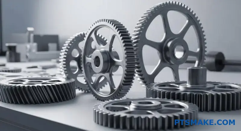
أنت تقوم بإعادة تصميم نظام نقل الحركة، وتتسبب التروس المحفزة في إحداث مستويات ضوضاء غير مقبولة. إن الجدول الزمني لمشروعك ضيق، وميزانيتك محدودة، والتبديل إلى التروس الحلزونية يعني إعادة تصميم نظام المحمل والمبيت بالكامل.
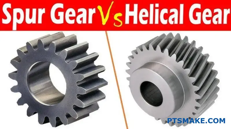
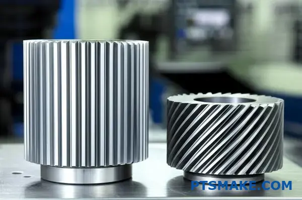
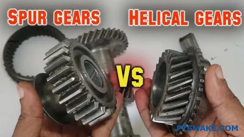
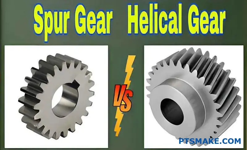
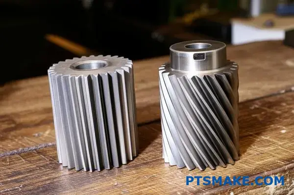
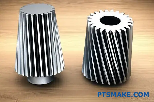
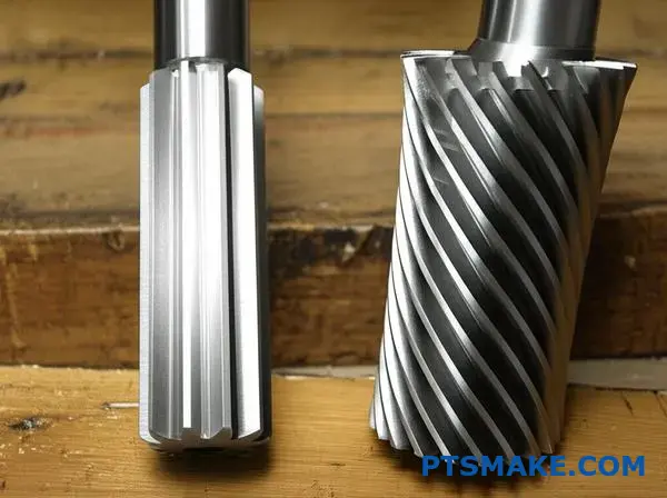
تتميز التروس المحفزة بأسنان مستقيمة موازية لمحور العمود، في حين أن التروس الحلزونية لها أسنان بزاوية تخلق حلزونًا حول محيط الترس. ويؤثر هذا الاختلاف الأساسي على كل شيء بدءًا من مستويات الضوضاء وسعة التحميل إلى تكاليف التصنيع ومتطلبات التحمل.
من خلال عملي في شركة PTSMAKE، ساعدت المهندسين في اتخاذ هذا القرار بالضبط عشرات المرات. لكل نوع ترس نقاط قوة محددة تجعله مثاليًا لتطبيقات معينة. سيرشدك هذا الدليل إلى الاختلافات التقنية ومقايضات الأداء ومعايير الاختيار لمساعدتك في اتخاذ القرار الصحيح لمشروعك.
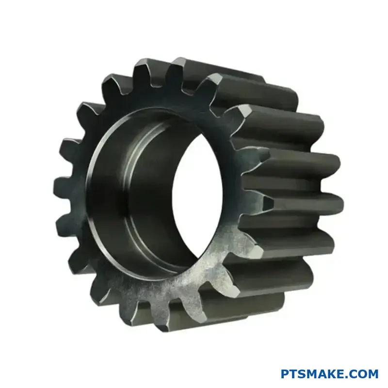
ما هي الهندسة الأساسية التي تحدد سن الترس المحفز؟
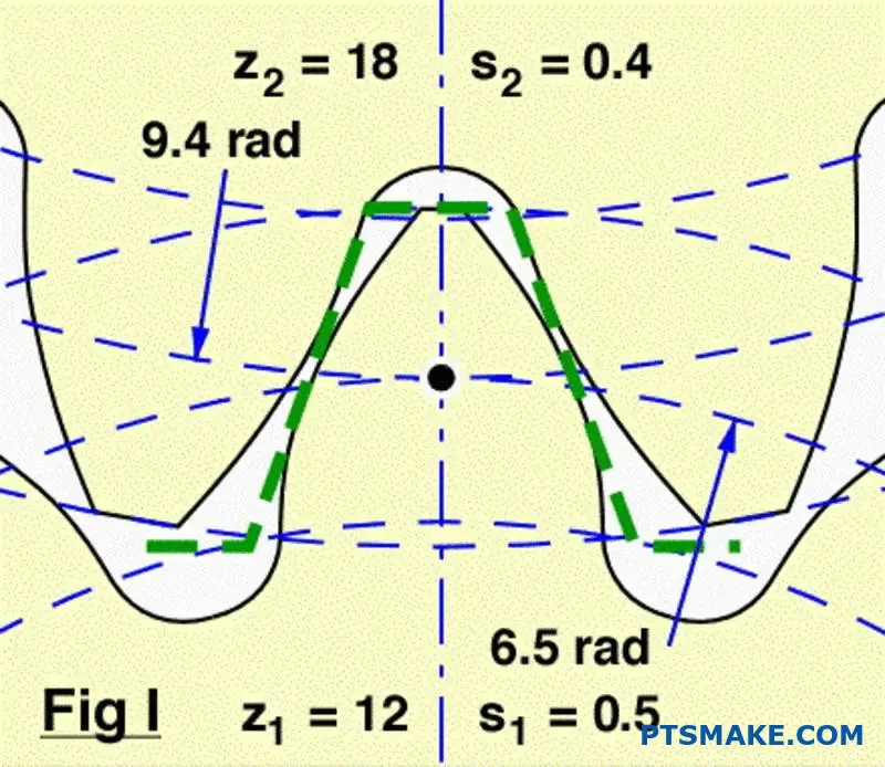
لا يكمن السر وراء أداء الترس المحفز في شكله فقط، بل في منحنى محدد للغاية. هذا المنحنى هو أساس تصميمه.
ملف إنفلولوت الشخصي
في جوهرها، يكون شكل السن في الترس المحفّز الحديث عبارة عن منحنى غير ملتوٍ. فكر في الأمر على أنه فك خيط من أسطوانة.
هذه الهندسة المحددة أمر بالغ الأهمية. فهي تضمن أنه عندما تتشابك التروس، تظل سرعة الدوران ثابتة تماماً. ويمنع ذلك حدوث اهتزازات وتفاوت في تدفق الطاقة.
| خاصية الهندسة | الغرض |
|---|---|
| منحنى إنفولوت | نسبة السرعة الثابتة |
| الأسنان المستقيمة | نقل الطاقة المحوري |
| التباعد المناسب | المشاركة السلسة |
كيف يضمن إنفولوت التشغيل السلس
الشكل الملتوي ليس اعتباطياً. إنه شكل رياضي دقيق مصمم لسبب أساسي واحد: الحفاظ على نسبة سرعة ثابتة بين التروس المتشابكة. وهذا مبدأ غير قابل للتفاوض لنقل الطاقة بكفاءة.
سحر الوضع الطبيعي المشترك
عند تلامس اثنين من أسنان الترسين، يمر العمودي المشترك (خط عمودي على السطحين عند نقطة التلامس) دائمًا بنقطة ثابتة. وتسمى هذه النقطة الثابتة نقطة الميل.
تضمن هذه الهندسة المتسقة أن ترس القيادة يدفع الترس المدفوع بمعدل ثابت. لا توجد تسارعات أو تباطؤات أثناء الشبكة. وهذا فرق رئيسي عند مقارنة التروس المحفزة مقابل التروس الحلزونيةحيث يعتمد كلاهما على هذا المبدأ للتشغيل السلس.
يتولَّد المنحنى الملتوي من دائرة القاعدة1. يعد حجم هذه الدائرة أساسيًا لشكل السن النهائي وخصائص أدائها. في عملنا في شركة PTSMAKE، يعد الحصول على هذه الهندسة بشكل صحيح أمرًا بالغ الأهمية بالنسبة للقطع عالية الدقة التي يعتمد عليها عملاؤنا.
| جانب التصميم | نتيجة الهندسة غير المطلقة |
|---|---|
| نقطة الاتصال | يتحرك على طول وجه السن |
| خط العمل | يظل ثابتًا ومماسًّا لكلتا دائرتي القاعدة |
| نسبة السرعة | يبقى ثابتًا في جميع أنحاء الشبكة |
المنحنى الملتوي هو الهندسة الأساسية لسن التروس المحفزة. هذا المظهر الجانبي المحدد ضروري لتحقيق نسبة سرعة ثابتة، وهو ما يضمن سلاسة وموثوقية وفعالية نقل الطاقة بين التروس المتشابكة.
كيف تغير الزاوية الحلزونية طبيعة الترس بشكل أساسي؟
الزاوية الحلزونية هي الميزة الوحيدة الأكثر أهمية. فهي تفصل الترس الحلزوني عن الترس المحفز. إنها ليست مجرد تعديل بصري.
التروس المحفزة لها أسنان مستقيمة. يتم تعشيقها على طول وجهها بالكامل مرة واحدة. وهذا يخلق تلامسًا مفاجئًا على خط مستقيم.
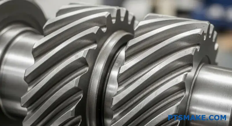
التروس الحلزونية، بأسنانها ذات الزوايا، تتلامس بشكل مختلف. يبدأ التلامس عند أحد طرفي السن. ثم يتحرك بسلاسة عبر الوجه أثناء دوران الترس.
هذه المشاركة التدريجية هي المفتاح.
| الميزة | ترس محفز | ترس حلزوني |
|---|---|---|
| محاذاة الأسنان | مستقيم | الزاوية (الزاوية الحلزونية) |
| الاتصال الأولي | الخط الكامل | نقطة الاتصال |
| أسلوب الخطوبة | مفاجئ | التدرج والسلاسة |
آليات المشاركة التدريجية
تغير عملية الربط التدريجي هذه كل شيء. على عكس التأثير المفاجئ للتروس المحفزة فإن الأسنان الحلزونية تنزلق في مكانها. يتم تطبيق الحمل تدريجياً، وليس دفعة واحدة. وهذا يقلل بشكل كبير من الصدمات والاهتزازات.
والنتيجة هي تشغيل أهدأ بكثير. وهذا هو السبب الرئيسي وراء اختيار المصممين للتروس الحلزونية على التروس المحفزة. في المشاريع السابقة في شركة PTSMAKE، أدى التحول إلى التروس الحلزونية إلى تقليل ضوضاء التشغيل بهامش ملحوظ. وهذا أمر بالغ الأهمية للأجهزة الطبية والإلكترونيات الاستهلاكية.
ومع ذلك، فإن هذا التلامس المائل يخلق تأثيرًا جانبيًا. فهو يولِّد الدفع المحوري2قوة موازية لمحور الترس. هذه القوة غير موجودة في التروس المحفزة ويجب إدارتها. يعد اختيار المحمل المناسب أمرًا ضروريًا للتعامل مع هذا الحمل ومنع الفشل المبكر.
يكمن جوهر النقاش حول التروس المحفزة مقابل التروس الحلزونية في هذه المفاضلة.
| جانب المشاركة | الميزة | العيب |
|---|---|---|
| الاتصال التدريجي | تشغيل أكثر سلاسة وهدوءاً | يخلق دفعاً محورياً |
| أسنان بزاوية | نسبة تلامس إجمالية أعلى | يتطلب محامل قوية |
| توزيع الأحمال | زيادة سعة الحمولة | تصنيع أكثر تعقيدًا |
التحول في توزيع الأحمال
ويعني هذا التعشيق التدريجي أيضاً أن الحمل مشترك بين عدة أسنان في أي لحظة معينة. وهذا يتناقض مع التروس المحفزة، حيث يتحمل سن واحد أو اثنين من الأسنان الحمل بالكامل. هذه القدرة على المشاركة تسمح للتروس الحلزونية بالتعامل مع أحمال أكبر وعمر خدمة أطول.
تغير الزاوية الحلزونية بشكل أساسي تلامس التروس من خط مفاجئ إلى منطقة سلسة ومتدرجة. هذا التحول هو مصدر مزاياها في الضوضاء وقدرة التحميل، ولكنه يقدم أيضًا تحدي الدفع المحوري.
ما القوى المؤثرة على سن ترس محفز واحد أثناء الربط؟
لكي نفهم حقًا ما يحدث أثناء ربط الترسين، يجب أن نحلل القوة الكلية. لا تؤثر هذه القوة بشكل مستقيم. بل تؤثر بزاوية مع سطح السن.
يقوم المهندسون بتبسيط ذلك من خلال تقسيم القوة إلى مكونين رئيسيين. وهذا يجعل التحليل والتصميم أسهل بكثير. هذه هي القوى العرضية والقوة الشعاعية. لكل منهما تأثير مختلف تمامًا على نظام التروس.
فهم مكونات القوة
فيما يلي تفصيل سريع لهاتين القوتين وأدوارهما الأساسية في نظام التروس.
| مكون القوة | الوظيفة الأساسية | التأثير الرئيسي |
|---|---|---|
| القوة العرضية | ينقل الطاقة | توليد عزم دوران لدفع الحمل |
| القوة الشعاعية | يفصل بين التروس | يضع الحمل على المحامل والأعمدة |
القوة "العاملة" المكوّن العرضي
القوة العرضية هي المكون الذي يقوم بكل العمل المفيد. فهي تعمل بشكل مماس لدائرة ميل الترس. وهذه هي القوة التي تنقل عزم الدوران بالفعل وتجعل الترس المدفوع يدور. عندما تحتاج إلى عزم دوران أكبر، فأنت تتعامل مع قوة عرضية أكبر.
القوة الفاصلة المكوِّن الشعاعي
من ناحية أخرى، لا تقوم القوة الشعاعية بأي عمل مفيد لنقل الطاقة. وتتمثل مهمتها في دفع الترسين بعيدًا عن بعضهما البعض، حيث تعمل على طول خط يربط بين مركزيهما. وتعتبر قوة الفصل هذه عاملاً حاسمًا في التصميم. فهي تحمل مباشرة الأعمدة والمحامل التي تدعمها.
في المشاريع السابقة في PTSMAKE، رأينا تصميمات تفشل بسبب عدم تحديد المحامل للتعامل مع الأحمال الشعاعية. هذا تمييز حاسم في النقاش حول التروس المحفزة مقابل التروس الحلزونية، حيث أن التروس الحلزونية تقدم أيضًا قوة محورية (دفع).
يُحدَّد مقدار هذه القوى من خلال ترس الترس زاوية الضغط3. تزيد الزاوية الأعلى من القوة الشعاعية بالنسبة إلى القوة المماسية.
نظرة عامة على اتجاه القوة
| القوة | اتجاه العمل | العواقب |
|---|---|---|
| عرضي | المماس لدائرة العرض والطلب | نقل عزم الدوران |
| شعاعي | نحو مركز التروس | حمولة التحميل |
يتم فهم القوة الكلية على سن الترس المحفز بشكل أفضل من خلال مكوناتها المماسية والقطرية. تدفع القوة المماسية الماكينة، بينما تخلق القوة الشعاعية أحمالاً على الأعمدة والمحامل. يأخذ التصميم المناسب كلاهما في الحسبان.
ما هو عنصر القوة الجديد الذي أدخلته التروس الحلزونية؟
تقدم التروس الحلزونية مكون قوة كبير غير موجود في التروس المحورية: الدفع المحوري. تعمل هذه القوة بشكل موازٍ لمحور الترس، مما يدفع الترس بشكل أساسي إلى الجانب.
يكمن أصله في الأسنان المائلة للترس.
الفرق الرئيسي في التصميم
عندما تتشابك الأسنان الحلزونية، ينتج عن التلامس قوة غير متعامدة على العمود. وهذا ينشئ المكون المحوري.
| نوع العتاد | القوات الأساسية | مكون القوة الجديدة |
|---|---|---|
| ترس محفز | شعاعي، عرضي | لا يوجد |
| ترس حلزوني | شعاعي، عرضي | الدفع المحوري |
تتطلب هذه القوة الجديدة إدارة دقيقة في تصميمك.
الفيزياء الكامنة وراء الدفع المحوري
الزاوية الحلزونية هي السبب المباشر للدفع المحوري. أثناء انتقال القوة، تكون القوة على سطح السن عمودية على السن نفسه. ولأن السن بزاوية، تتحلل هذه القوة إلى مكونين رئيسيين.
إحداهما هي القوة المماسية التي تدفع الدوران. والأخرى هي القوة المحورية التي تدفع على طول العمود. هذا هو المفهوم الأساسي عند مقارنة التروس المحفزة مقابل التروس الحلزونية. كلما زادت زاوية اللولب، زادت قوة الدفع المحورية لعزم دوران معين.
حساب التأثير
هذا الدفع ليس مشكلة بسيطة. يجب مواجهته بواسطة محامل مناسبة، مثل المحامل الأسطوانية المخروطية المخروطية أو محامل الدفع. يمكن أن يؤدي تجاهلها إلى فشل المحامل قبل الأوان واختلال النظام.
يؤدي الحمل الكلي على السن إلى تكوين القوة المحصلة4 التي هي مزيج من هذه المكونات. في عملنا في شركة PTSMAKE، نقوم بحساب هذه الأحمال بدقة لضمان أداء كل مكوّن نقوم بتصنيعه بشكل موثوق في التجميع النهائي.
التأثير المباشر للزاوية الحلزونية
| زاوية اللولب الحلزوني | الدفع المحوري النسبي |
|---|---|
| 15° | منخفضة |
| 30° | متوسط |
| 45° | عالية |
هذه العلاقة حاسمة بالنسبة للمهندسين. يأتي اختيار زاوية حلزونية أعلى لتشغيل أكثر سلاسة مع مفاضلة إدارة أحمال محورية أكبر.
تُدخل التروس الحلزونية قوة دفع محورية بسبب أسنانها المائلة. تتناسب هذه القوة طرديًا مع عزم الدوران المنقول وظل الزاوية الحلزونية. يعد اختيار المحمل المناسب أمرًا ضروريًا لإدارة هذا الحمل، وهو اعتبار حاسم غير موجود في أنظمة التروس المحفزة.
كيف يتم تعريف "نسبة التلامس" للتروس المحفزة والحلزونية؟
نسبة التلامس هي مقياس رئيسي للتروس. وهي تحدد متوسط عدد أزواج الأسنان المتلامسة في أي وقت معين. النسبة الأعلى تعني مشاركة عدد أكبر من الأسنان في الحمل.
وينتج عن ذلك نقل طاقة أكثر سلاسة. كما أنه يقلل من الضوضاء والاهتزاز بشكل كبير.
نسب التلامس الحلزونية مقابل نسب التلامس الحلزونية
يؤثر تصميم أسنان التروس بشكل مباشر على هذه النسبة. دعونا نقارن بينهما.
| نوع العتاد | نسبة التلامس النموذجية | اشتباك الأسنان |
|---|---|---|
| ترس محفز | 1.2 إلى 1.8 | متسلسل، يتم تعشيق زوج مع فك ارتباط الآخر |
| ترس حلزوني | > 2.0 | تداخل، أزواج متعددة في اتصال في وقت واحد |
هذا الاختلاف أساسي في أدائهم.
فهم ميكانيكيات نسبة التلامس
يرجع الفرق في نسبة التلامس إلى هندسة الأسنان. التروس المحفزة لها أسنان مستقيمة. وهذا يعني أن التلامس يحدث على طول وجه السن بالكامل مرة واحدة. ويكون الاشتباك مفاجئاً.
أما التروس الحلزونية فلها أسنان بزاوية. وهذا يخلق اشتباكاً تدريجياً. يبدأ التلامس عند أحد طرفي السن ويمتد عبر وجهه أثناء دوران الترس.
التعشيق التدريجي في التروس الحلزونية
يعمل هذا التصميم المائل على تمديد مسار الاتصال5. فهو يسمح لزوج جديد من الأسنان بالبدء في التعشيق قبل أن ينفصل الزوج السابق بالكامل. هذا التداخل هو السبب في أن نسبة التلامس بينهما دائمًا أكبر من 2.0.
من خلال خبرتنا في PTSMAKE، يعد هذا عاملاً حاسماً. عندما يناقش العملاء التروس المحفزة مقابل التروس الحلزونية بالنسبة للتطبيقات التي تتطلب ضوضاء منخفضة، فإن نسبة التلامس الأعلى للتروس الحلزونية تجعلها الخيار الواضح في كثير من الأحيان.
الآثار العملية
توزع نسبة التلامس الأعلى الحمل على عدد أكبر من الأسنان. وهذا يقلل من الضغط على الأسنان الفردية. ويعزز قدرة حمل الحمولة ويطيل العمر التشغيلي للترس.
| الميزة | ترس محفز (نسبة أقل) | ترس حلزوني (نسبة أعلى) |
|---|---|---|
| توزيع الأحمال | مركزة على 1-2 أزواج من الأسنان | موزعة على أكثر من زوجين من الأسنان |
| مستوى الضوضاء | أعلى | أقل |
| الاهتزاز | أكثر وضوحاً | تشغيل أكثر سلاسة |
| الضغط على الأسنان | أعلى | أقل |
وهذا يجعل التروس الحلزونية مثالية للتطبيقات عالية السرعة وعالية الطاقة حيث تكون السلاسة ضرورية.
تقيس نسبة التلامس تعشيق الأسنان المتزامن. تتميز التروس الحلزونية بنسبة تداخل أعلى ومتداخلة مقارنة بالتروس المحفزة. ويؤدي ذلك إلى تشغيل أكثر سلاسة وهدوءاً وتوزيعاً أفضل للحمل، وهو تمييز حاسم في اختيار التروس.
ما الظاهرة الفيزيائية التي تعتبر المصدر الرئيسي لضوضاء التروس المحفزة؟
جوهر المشكلة هو التصادم. إن المصدر الرئيسي لضوضاء التروس المحفزة هو التصادم المفاجئ والوجه الكامل للأسنان عند تعشيقها.
على عكس التدحرج السلس، فهذا حدث مفاجئ. يخلق هذا التصادم ارتفاعاً فورياً في الضغط.
ويسبب هذا التغير في الضغط اهتزازات. وتنتقل هذه الاهتزازات عبر مادة الترس والهواء المحيط، والتي تكتشفها آذاننا كضوضاء.
تتكرر العملية مع كل سن من الأسنان المتشابكة، مما يخلق أنيناً مميزاً.
| الخطوة | العمل البدني | النتيجة |
|---|---|---|
| 1. المشاركة | تصادم الأسنان بشكل مفاجئ | الصدمة المفاجئة |
| 2. الأثر | نقل الطاقة | ارتفاع الضغط الحاد |
| 3. الانتشار | يشع السنبلة إلى الخارج | الاهتزاز (الضوضاء) |
هذا التأثير السريع والمتكرر هو الظاهرة الفيزيائية الأساسية التي نحتاج إلى معالجتها.
آليات المشاركة المفاجئة
دعونا نتعمق أكثر في هذا التأثير. تلتقي أسنان التروس المحفزة على طول عرضها بالكامل في وقت واحد. هذا التلامس الخطي اللحظي يعني عدم وجود نقل تدريجي للحمل. إنه حدث كل شيء أو لا شيء.
هذا التحميل بالصدمة هو السبب الجذري. يعمل كل اشتباك مثل ضربة مطرقة صغيرة على النظام، مما يخلق موجة ضغط.
من الاهتزاز إلى الضوضاء المسموعة
تشع موجة الضغط هذه بعيدًا عن التروس. وعندما تنتقل عبر الهواء، ندركها كصوت. ويرتبط تردد هذا الصوت ارتباطاً مباشراً بعدد مرات تشابك الأسنان.
في PTSMAKE، غالبًا ما نرى كيف تؤثر هذه الطاقة المفقودة على الكفاءة، وليس فقط على الصوتيات. فالضوضاء التي تسمعها هي طاقة مهدرة يمكن أن تقوم بعمل مفيد. العامل الرئيسي هو تباين صلابة الأسنان6 أثناء دورة التشبيك، مما قد يؤدي إلى تضخيم هذه الاهتزازات.
هذه نقطة اختلاف رئيسية في النقاش حول التروس المحفزة مقابل التروس الحلزونية. تتشابك التروس الحلزونية بشكل تدريجي عبر وجه السن، مما يخفف من هذا التأثير بشكل كبير.
| نوع العتاد | أسلوب الخطوبة | مستوى التأثير | الضجيج النموذجي |
|---|---|---|---|
| ترس محفز | لحظي، كامل العرض | عالية | صاخب |
| ترس حلزوني | متدرجة، بزاوية | منخفضة | هدوء |
تُظهر اختباراتنا أن هذا الاختلاف الأساسي في ميكانيكا التعشيق هو السبب الرئيسي للتفاوت في الضوضاء. إن معالجة هذا التأثير هو المفتاح لتشغيل أكثر هدوءاً.
إن المصدر الرئيسي لضوضاء التروس المحفزة هو التأثير المفاجئ للأسنان أثناء التعشيق. وهذا يخلق تغيرات مفاجئة في الضغط والاهتزازات. إن الطبيعة الفورية لهذا التلامس هي الظاهرة الفيزيائية الأساسية المسؤولة عن أنين التروس المميز.
لماذا تعتبر التروس الحلزونية بطبيعتها أكثر هدوءًا من التروس المحفزة؟
السبب الرئيسي هو "المشاركة التدريجية". إنه مفهوم بسيط له تأثير كبير على الضوضاء.
على عكس التروس المحفزة، تكون أسنان التروس الحلزونية بزاوية. وهذا يعني أنها لا تتشابك كلها مرة واحدة.
سر الاتصال السلس
يبدأ التلامس عند نقطة واحدة على السن. ثم ينتشر بسلاسة عبر الوجه أثناء دوران التروس.
وهذا يزيل الصدمات المفاجئة التي تسبب الضوضاء. إنه يخلق نقل طاقة أكثر سلاسة وهدوءاً.
| الميزة | ترس محفز | ترس حلزوني |
|---|---|---|
| اشتباك الأسنان | مفاجئ، كامل العرض | تدريجي، من نقطة إلى خط |
| مستوى التأثير | عالية | منخفضة |
| الاهتزاز | مهم | الحد الأدنى |
آليات التشغيل الهادئ
لنتعمق أكثر في هذا الأمر. تتشابك التروس المحفزة على طول وجه السن بالكامل على الفور. يخلق هذا التلامس المفاجئ حملاً صادمًا، وهو المصدر الرئيسي لضوضاء واهتزاز التروس. إنه يشبه التصفيق بيديك - صوت مفاجئ وحاد.
من التأثير إلى التدفق
تغير التروس الحلزونية هذه الديناميكية بالكامل. حيث تضمن الأسنان ذات الزوايا أنه عندما يدور جزء من السن خارج الشبكة، يبدأ جزء آخر في الاشتباك بالفعل. ويخلق هذا التداخل تدفقاً مستمراً وغير متقطع للطاقة.
هذا التسليم السلس بين الأسنان أمر أساسي. فهو يمنع طفرات الضغط التي تولد الضوضاء.
فهم نمط الاتصال
إن خط الاتصال7 على سن ترس حلزوني يتحرك قطرياً عبر سطحه. هذا التعشيق وفك الارتباط التدريجي هو ما يجعل العملية هادئة للغاية.
في PTSMAKE، نقوم بتصنيع هذه الزوايا بدقة عالية. وهذا يضمن توزيع الحمل بالتساوي، مما يزيد من الهدوء وعمر التروس إلى أقصى حد. عند التفكير في التروس المحفزة مقابل التروس الحلزونية، غالبًا ما يكون هذا النقل السلس هو العامل الحاسم لعملائنا في المجالات الحساسة للضوضاء.
| الخصائص | ترس محفز | ترس حلزوني |
|---|---|---|
| تطبيق التحميل | حمل الصدمة المفاجئة | الحمل التدريجي الموزع |
| نقل الطاقة | مقاطعة على مستوى الأسنان | متواصل، سلس |
| الضوضاء الناتجة | "أنين" عالي التردد | همهمة منخفضة وثابتة |
تسمح الأسنان ذات الزوايا في التروس الحلزونية بالتعشيق التدريجي. وتقلل هذه العملية من الصدمات والصدمات والاهتزازات التي تجعل التروس المحفزة صاخبة. والنتيجة هي نقل أكثر سلاسة وهدوءاً للطاقة.
ما هي مقايضات الأداء الرئيسية بين هذين الترسين؟
لا يتعلق الاختيار بين التروس المحفزة والحلزونية بأيهما أفضل. بل يتعلق الأمر بفهم المفاضلات المحددة للتطبيق الخاص بك. يتفوق كل نوع من التروس في مجالات مختلفة.
يؤثر قرارك على الضوضاء وسعة التحميل والتكلفة والتعقيد. يمكن أن توضح المقارنة المنظمة بين التروس المحفزة مقابل التروس الحلزونية الخيار الأفضل. فيما يلي نظرة عامة سريعة.
| الميزة | ترس محفز | ترس حلزوني |
|---|---|---|
| مستوى الضوضاء | أعلى | أقل |
| الدفع المحوري | لا يوجد | حاضر |
| التكلفة | أقل | أعلى |
| سعة الحمولة | جيد | ممتاز |
يساعد هذا الإطار على تحقيق التوازن بين الأداء وقيود المشروع.
يتطلب اتخاذ القرار الصحيح إلقاء نظرة أعمق على محاور الأداء هذه. فكل قرار ينطوي على حل وسط يمكن أن يؤثر بشكل كبير على منتجك النهائي. في PTSMAKE، نوجه العملاء خلال هذه العملية يومياً.
الضوضاء مقابل الدفع المحوري
تتميز التروس الحلزونية بهدوء التشغيل. حيث تتشابك أسنانها ذات الزوايا بشكل تدريجي، مما يقلل من صوت الأنين الشائع مع التروس المحفزة. وهذا يجعلها مثالية للمنتجات الاستهلاكية أو ناقل الحركة في السيارات.
ومع ذلك، فإن هذا التصميم المائل يخلق الدفع المحوري8. هذه قوة موازية لمحور الترس. وتتطلب محامل دفع لإدارتها، مما يضيف تعقيدًا وتكلفة إلى التجميع. لا تنتج التروس المحفزة مثل هذه القوة.
البساطة مقابل سعة الحمولة
التروس المحفزة أسهل في التصميم والتصنيع. أسنانها المستقيمة تجعلها سهلة القطع والتركيب. وتترجم هذه البساطة إلى تكاليف أقل وصيانة أسهل.
يمكن للتروس الحلزونية، بهندستها المعقدة، تحمل أحمال أعلى. توفر الأسنان ذات الزوايا مساحة تلامس أكبر، مما يوزع الضغط بشكل أكثر فعالية. وهذه ميزة رئيسية في التطبيقات عالية العزم.
التكلفة مقابل السلاسة
تؤثر عملية التصنيع بشكل مباشر على التكلفة. الطحن الدقيق اللازم للتروس الحلزونية يجعلها أكثر تكلفة من التروس المحفزة. وهذا الفرق في التكلفة يمكن أن يكون كبيراً في عمليات الإنتاج الكبيرة.
في مقابل التكلفة الأعلى، توفر التروس الحلزونية نقل طاقة سلس ومتسق بشكل استثنائي. هذه السلاسة ضرورية للآلات الدقيقة حيث يكون الاهتزاز غير مرغوب فيه.
الكفاءة مقابل التعقيد
التروس المحفزة ذات كفاءة عالية، وغالباً ما تصل إلى 98-99%. تلامسها المتداول يولد احتكاكاً ضئيلاً للغاية.
تُدخل التروس الحلزونية حركة انزلاقية بين الأسنان، مما قد يقلل قليلاً من الكفاءة بسبب الاحتكاك. ومع ذلك، غالبًا ما تكون هذه مقايضة بسيطة مقابل أدائها المتفوق في مجالات أخرى.
الاختيار بين التروس المحفزة والحلزونية هو عملية موازنة. ستحدد أولوياتك - سواء كانت الضوضاء المنخفضة أو سعة التحميل العالية أو الميزانية أو بساطة التصميم - الترس المثالي. لا توجد إجابة واحدة "أفضل"، فقط أفضل ما يناسب استخدامك المحدد.
كيف تقارن قدرة حمل الأحمال بين التروس المحفزة والحلزونية؟
عند المقارنة بين التروس المحفزة والتروس الحلزونية من نفس الحجم والمادة، تتفوق التروس الحلزونية باستمرار في قدرة حمل الأحمال. وهذا ليس بهامش صغير أيضاً.
يأتي الاختلاف من تصميمها الأساسي. تتشابك التروس المحفزة بشكل مفاجئ عبر وجه السن بالكامل مرة واحدة.
تتشابك التروس الحلزونية، بأسنانها ذات الزوايا، بشكل تدريجي. ويؤدي هذا الانتقال الأكثر سلاسة إلى توزيع الحمل بشكل أكثر فعالية، مما يسمح بأداء أعلى في ظروف مماثلة.
| نوع العتاد | سعة الحمولة النموذجية | العامل الرئيسي |
|---|---|---|
| ترس محفز | أقل | تلامس فوري وكامل للوجه بالكامل |
| ترس حلزوني | أعلى | الاتصال التدريجي الموزع |
الآليات الكامنة وراء القدرة العالية
تنبع قدرة التحميل الفائقة للتروس الحلزونية من ميزتين ميكانيكيتين رئيسيتين. وهو مفهوم نوضحه كثيرًا للعملاء في شركة PTSMAKE عند اختيار الترس المناسب للتطبيقات الصعبة.
المشاركة التدريجية ومشاركة الأحمال
على عكس التأثير المفاجئ لأسنان التروس المحفزة فإن الأسنان الحلزونية تنزلق عند التلامس. يتم تطبيق الحمل تدريجيًا، بدءًا من أحد طرفي السن ويتحرك عبر وجهه.
وهذا يعني أن العديد من الأسنان غالباً ما تكون على تلامس في وقت واحد، مما يعني مشاركة الحمل الكلي. تقلل نسبة التلامس المتزايدة هذه بشكل كبير من الضغط على أي سن واحد. توزيع إجهاد التلامس الهرتزي9 أكثر كفاءة بكثير.
شرح نسبة التلامس المتزايدة
ونسبة التلامس هي مقياس لعدد الأسنان المتشابكة في أي وقت. تعني النسبة الأعلى توزيعاً أفضل للحمل وتشغيلاً أكثر سلاسة. في اختباراتنا، تُظهر التروس الحلزونية نسبة تلامس أعلى بكثير.
| الميزة | ترس محفز | ترس حلزوني |
|---|---|---|
| اشتباك الأسنان | فجأة، دفعة واحدة | تدريجيًا وتدريجيًا |
| توزيع الأحمال | مركزة على زوج أسنان واحد | مشتركة عبر أسنان متعددة |
| نسبة التلامس النموذجية | 1.1 إلى 1.7 | 2.0 أو أعلى |
| الإجهاد الناتج | ذروة الإجهاد العالي | الضغط المنخفض والموزع |
ويسمح هذا التوزيع للتروس الحلزونية بالتعامل مع عزم دوران وقوة أكبر دون زيادة خطر التعطل من إجهاد الانحناء أو تنقر السطح.
تتفوق التروس الحلزونية على التروس المحفزة في القدرة على حمل الأحمال بسبب أسنانها ذات الزوايا. ويضمن هذا التصميم نسبة تلامس أعلى وتطبيق تدريجي للحمل، مما يوزع الضغط عبر أسنان متعددة ويؤدي إلى نقل طاقة أكثر سلاسة وقوة في ظل ظروف مماثلة.
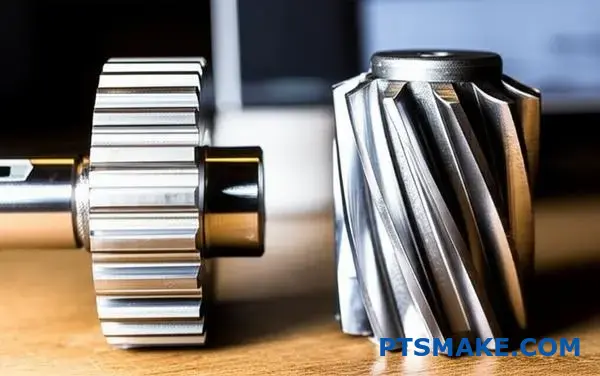
كيف تقارن تكاليف التصنيع والتعقيد؟
عند المقارنة بين التروس المحفزة والتروس الحلزونية، فإن التصنيع هو المحرك الأكبر للتكلفة. يعود الفرق إلى الهندسة.
بساطة التروس المحفزة
التروس المحفزة لها أسنان مستقيمة. وهذا التصميم البسيط يجعل إنتاجها أسهل بكثير. ويمكننا استخدام العمليات القياسية مثل التفكيك أو التشكيل.
يمكن قطع السن بالكامل بتمريرة واحدة. وهذا يؤدي إلى تسريع زمن الدورة وانخفاض التكاليف.
تعقيد التروس الحلزونية
التروس الحلزونية لها أسنان بزاوية. تقدم هذه الزاوية تعقيداً. يتطلب التصنيع إعدادات ماكينة أكثر دقة وأدوات متخصصة لإنشاء اللولب.
| نوع العتاد | سهولة التصنيع | العملية النموذجية |
|---|---|---|
| ترس محفز | عالية | التثبيت، والتشكيل |
| ترس حلزوني | معتدل | التثبيط المتخصص |
يُترجم هذا التعقيد مباشرةً إلى أوقات تصنيع أطول وتكاليف إنتاج أعلى.
تحكي عملية التصنيع نفسها قصة التكلفة. وبالنسبة للعديد من عملائنا في شركة PTSMAKE، فإن فهم هذا الأمر هو مفتاح وضع ميزانية مشاريعهم بفعالية.
التعمق أكثر في طرق التصنيع الآلي
تصنيع التروس المحفزة آلياً
تصنيع التروس المحفزة عملية مباشرة للغاية. وغالباً ما نستخدم ماكينة التفاف. تدور أداة القطع، أو الموقد، وفراغ التروس معًا. يقطع الموقد الأسنان المستقيمة بكفاءة.
هذه العملية مؤتمتة وسريعة للغاية. تتطلب إعدادات أقل تعقيدًا، مما يقلل من العمالة ووقت الماكينة. وهذا هو السبب الرئيسي لفعاليتها من حيث التكلفة.
تصنيع التروس الحلزونية
إنتاج التروس الحلزونية أكثر تعقيدًا. يجب أن تقطع الماكينة الأسنان بزاوية حلزونية محددة. ويتطلب ذلك حركة حلزونية متزامنة ومتزامنة بين الموقد وفراغ الترس.
تخلق هذه العملية أيضًا الدفع المحوري10تتطلب إعدادات قوية للماكينة للحفاظ على الدقة. يستغرق الإعداد وقتًا أطول، وغالبًا ما تكون سرعات القطع أبطأ لضمان الدقة.
| الميزة | تصنيع التروس المحفزة آلياً | تصنيع التروس الحلزونية |
|---|---|---|
| مسار الأداة | مستقيم، موازٍ للمحور | مسار حلزوني مائل بزاوية |
| إعداد الماكينة | أبسط وأسرع | أكثر تعقيداً، يتطلب مزامنة الزوايا |
| وقت الدورة | أقصر | أطول |
| الأدوات | موقد قياسي | موقد خاص بالزاوية |
| القوات المرتبطة | القوى الشعاعية في المقام الأول | القوى الشعاعية والمحورية |
كل خطوة تضيف وقتًا وتتطلب مهارة أكبر من المشغل، مما يزيد من التكلفة النهائية لكل جزء.
التروس المحفزة أرخص وأسرع في الإنتاج بسبب هندسة أسنانها البسيطة والمستقيمة. أما التروس الحلزونية، بأسنانها ذات الزوايا، فتتطلب إعدادات تصنيع أكثر تعقيدًا، وأدوات متخصصة، وأزمنة دورات أطول، مما يؤدي إلى زيادة تكاليف التصنيع.
ما أنواع ترتيبات المحامل اللازمة لكل نوع من التروس؟
اختيار المحمل المناسب أمر بالغ الأهمية. فهو يؤثر بشكل مباشر على أداء نظام التروس وعمره الافتراضي. يعود الفرق الأساسي إلى القوى التي يولدها كل نوع من التروس.
احتياجات محمل التروس المحفزة
التروس المحفزة لها أسنان مستقيمة. ولهذا السبب، فإنها تنتج أحمالاً شعاعية بشكل أساسي. وهذا يبسط اختيار المحامل. تحتاج المحامل فقط إلى دعم العمود ضد هذه القوى الخارجية.
احتياجات محمل التروس الحلزونية
التروس الحلزونية، بأسنانها ذات الزوايا، أكثر تعقيدًا. فهي تولد أحمالاً شعاعية ومحورية كبيرة. وهذا يتطلب ترتيب محمل أكثر قوة للتعامل مع القوى من اتجاهات متعددة.
مقارنة سريعة بين التروس المحفزة مقابل التروس الحلزونية الأحمال أدناه.
| نوع العتاد | الحِمل الأساسي | الحِمل الثانوي |
|---|---|---|
| ترس محفز | شعاعي | الحد الأدنى |
| ترس حلزوني | شعاعي | محوري (الدفع) |
التعمق أكثر في اختيار المحامل
تملي خصائص الحمل لكل نوع من أنواع التروس ترتيب المحامل. إنه مفهوم أساسي نؤكد عليه دائمًا في استشارات التصميم لدينا في PTSMAKE. يؤدي الخطأ في ذلك إلى فشل سابق لأوانه.
محامل التروس المحفزة
بالنسبة للتروس المحفزة، ينصب التركيز على إدارة القوى الشعاعية. وغالباً ما تعمل أنواع المحامل البسيطة بشكل جيد.
المحامل الكروية ذات الأخدود العميق هي خيار شائع. فهي فعالة من حيث التكلفة وتتعامل مع الأحمال الشعاعية بكفاءة. في بعض التطبيقات ذات الأحمال العالية، يمكن استخدام المحامل الأسطوانية الأسطوانية للحصول على قدرة شعاعية أكبر.
محامل التروس الحلزونية
التروس الحلزونية مختلفة. تخلق الزاوية الحلزونية للأسنان قوة دفع مستمرة على طول محور العمود. تُعرف هذه القوة باسم الدفع المحوري11.
يتطلب ملف الحمل المشترك هذا حلولاً أكثر تقدماً. لا يكفي عادةً محمل كروي واحد ذو أخدود عميق.
غالبًا ما نوصي بالمحامل الأسطوانية المخروطية. فهي مصممة للتعامل مع الأحمال الشعاعية والمحورية الثقيلة في وقت واحد. يعد ترتيبها في أزواج (من الخلف إلى الخلف أو وجهاً لوجه) ممارسة قياسية لمواجهة الدفع في كلا الاتجاهين.
فيما يلي دليل لاختيار المحمل.
| نوع العتاد | نوع المحمل الشائع | السبب |
|---|---|---|
| ترس محفز | محمل كريات الأخدود العميق | ممتازة للأحمال الشعاعية وفعالة من حيث التكلفة. |
| ترس حلزوني | محمل أسطواني مدبب | يتعامل مع الأحمال الشعاعية والمحورية العالية مجتمعة. |
باختصار، تتطلب التروس المحفزة محامل للأحمال الشعاعية. أما التروس الحلزونية فتحتاج إلى أنظمة قوية، مثل المحامل الأسطوانية المخروطية، لإدارة كل من القوى الشعاعية والمحورية الكبيرة. الاختيار المناسب هو المفتاح لموثوقية علبة التروس وأدائها على المدى الطويل.
ما هي الاستخدامات التي تعتبر فيها التروس المحفزة الخيار الأفضل؟
تتألق التروس المحفزة عندما تكون البساطة والتكلفة هي المفتاح. فهي تمثل أدوات نقل الطاقة المباشرة بين الأعمدة المتوازية.
تصميمها يزيل الدفع المحوري، مما يبسط متطلبات المحامل وتصميم المبيت. وهذا يجعلها مثالية للعديد من الماكينات.
معايير الاختيار الرئيسية
الفعالية من حيث التكلفة
عادة ما تكون التروس المحفزة أقل تكلفة في التصنيع من التروس الحلزونية. وهذا عامل رئيسي في الإنتاج بكميات كبيرة.
البساطة في التصميم
هندستها البسيطة تجعلها سهلة التصميم والتركيب. في شركة PTSMAKE، يمكننا تصنيعها آلياً وفق تفاوتات دقيقة بكفاءة.
| الميزة | التروس المحفزة | التروس الحلزونية |
|---|---|---|
| التكلفة | أقل | أعلى |
| الدفع المحوري | لا يوجد | حاضر |
| محاذاة العمود | بالتوازي فقط | متوازيان ومتعامدان |
| مستوى الضوضاء | أعلى | أقل |
التعمق في التطبيق
غالبًا ما يعود الاختيار في النقاش حول التروس المحفزة مقابل التروس الحلزونية إلى متطلبات التطبيق المحدد. لا تُعد التروس المحفزة مجرد خيار ميزانية؛ فهي الخيار الأفضل تقنيًا في سيناريوهات معينة. إن نقل الطاقة المباشر والفعال لا يهزم للأنظمة البسيطة.
الإرسال البسيط
فكر في الغسالات أو الخلاطات. تحتاج هذه الأجهزة إلى نقل عزم دوران موثوق به دون تعقيد أو تكلفة أنظمة التروس الأكثر تقدمًا. توفر التروس المحفزة ذلك بشكل مثالي. فهي تنجز المهمة بكفاءة وتبقي المنتج النهائي في متناول المستهلكين.
مضخات الإزاحة الموجبة
من خلال خبرتنا مع العملاء في صناعة طاقة السوائل، فإن الدقة غير قابلة للتفاوض. تعتمد المضخات التي تستخدم التروس المحفزة المتشابكة، والمعروفة باسم مضخات التروس، على النقل الثابت للحجم الناتج عن أسنان التروس. يضمن التصميم تدفقًا ثابتًا غير نابضًا، وهو أمر بالغ الأهمية للأنظمة الهيدروليكية. يجب أن تكون التروس دقيقة، وهي خدمة نحن متخصصون فيها في PTSMAKE من خلال التصنيع باستخدام الحاسب الآلي. هذه حالة كلاسيكية تتفوق فيها الهندسة البسيطة للتروس المحفزة على التروس المعقدة.
أنظمة النقل
تحتاج السيور الناقلة في المصانع أو المستودعات إلى حركة ثابتة وموثوقة. وهي تعمل بسرعات معتدلة حيث تكون الضوضاء أقل إثارة للقلق. توفر التروس المحفزة عزم الدوران اللازم لدفع السيور دون التكلفة والتعقيد الإضافيين للتعامل مع الأحمال المحورية. تضمن متانتها عمر خدمة طويل مع الحد الأدنى من الصيانة. وهذا أمر بالغ الأهمية للحفاظ على تشغيل خطوط الإنتاج بسلاسة.
| التطبيق | السبب الرئيسي لاختيار الترس المحفز |
|---|---|
| الغسالة | منخفضة التكلفة والبساطة |
| مضخات التروس | الدقة الإزاحة الإيجابية12، لا يوجد دفع محوري |
| الأحزمة الناقلة | الموثوقية والفعالية من حيث التكلفة |
| الأدوات الكهربائية | نقل عزم دوران عالي، تجميع بسيط |
التروس المحفزة هي الخيار الأفضل للتطبيقات التي تتسم بالبساطة والفعالية من حيث التكلفة وغياب الدفع المحوري. وهي تتفوق في أنظمة نقل الطاقة المباشرة مثل ناقل الحركة البسيط والمضخات والناقلات، مما يوفر الموثوقية وسهولة الصيانة.
ما هي التطبيقات التي تعتبر فيها التروس الحلزونية الخيار الإلزامي؟
عندما لا يمكن المساومة على الأداء، فإن التروس الحلزونية هي الخيار الوحيد. تصميمها مثالي للتطبيقات التي تحتاج إلى نقل طاقة سلس وهادئ. فكر في البيئات عالية السرعة والحمولة العالية.
لا يمكن للتروس المحفزة ببساطة أن تنافس هنا. يقلل التعشيق التدريجي للأسنان الحلزونية من الضوضاء والاهتزاز. وهذا يجعلها ضرورية في صناعات محددة.
تطبيقات عالية الأداء
ناقل الحركة في السيارات
في السيارات، وخاصة السيارات الكهربائية، يعد الحد من الضوضاء أمراً بالغ الأهمية. تضمن التروس الحلزونية قيادة هادئة وسلسة للركاب.
علب التروس الصناعية
بالنسبة للآلات الثقيلة والتوربينات، فإن الموثوقية هي المفتاح. تتعامل التروس الحلزونية مع الأحمال والسرعات العالية، مما يضمن استقراراً تشغيلياً طويل الأجل.
| التطبيق | المتطلبات الرئيسية | لماذا التروس الحلزونية؟ |
|---|---|---|
| السيارات | تشغيل هادئ | تقلل الأسنان المائلة من الضوضاء والاهتزازات. |
| التوربينات | طاقة عالية السرعة | تعشيق سلس يتعامل مع عدد دورات في الدقيقة العالية. |
| صناعي | سعة تحميل عالية | تلامس الأسنان الأكبر يوزع الضغط. |
في النقاش حول التروس المحفزة مقابل التروس الحلزونية، يحدد التطبيق الفائز. على الرغم من أن التروس المحفزة فعالة وأسهل في التصنيع، إلا أنها تصدر ضوضاء عند السرعات العالية. ويرجع ذلك إلى التلامس المفاجئ بين الأسنان.
تحل التروس الحلزونية هذه المشكلة. تتشابك الأسنان ذات الزوايا تدريجياً عبر وجه الترس. وهذا يخلق نقلًا أكثر سلاسة وهدوءًا للطاقة. تُظهر اختباراتنا في PTSMAKE باستمرار انخفاضاً كبيراً في الضوضاء والاهتزاز والخشونة (NVH).
المقايضة الهندسية
تأتي هذه العملية السلسة مصحوبة بمقايضة. تنتج الأسنان ذات الزوايا الدفع المحوري13قوة تدفع التروس بعيدًا عن بعضها البعض على طول أعمدتها. يجب إدارة هذه القوة باستخدام محامل مناسبة، مثل محامل الدفع.
وهذا يضيف بعض التعقيد والتكلفة إلى التصميم. ومع ذلك، بالنسبة للتطبيقات التي يكون فيها الأداء أمرًا بالغ الأهمية، فهو قرار هندسي ضروري. يمكن أن يؤدي تجاهله إلى فشل سابق لأوانه.
المزايا الخاصة بالتطبيق
| الميزة | مزايا السيارات | المنافع الصناعية |
|---|---|---|
| المشاركة السلسة | راحة محسّنة أثناء القيادة. | تقليل البلى على الماكينات. |
| قدرة عالية السرعة | مناسبة للمحركات الحديثة والمركبات الكهربائية. | ضرورية لتوربينات توليد الطاقة. |
| سعة تحميل أكبر | زيادة موثوقية الإرسال. | عمر أطول لعلب التروس للخدمة الشاقة. |
في PTSMAKE، نوجه العملاء من خلال هذه المفاضلات. ونساعدهم على اختيار نوع الترس المناسب وتصميم الأنظمة الداعمة لضمان الأداء الأمثل والمتانة المثلى لتطبيقاتهم المحددة.
بالنسبة للأنظمة عالية السرعة وعالية الطاقة مثل ناقل الحركة في السيارات والتوربينات الصناعية، تعتبر التروس الحلزونية إلزامية. يضمن تصميمها التشغيل السلس والهادئ، على الرغم من التعقيد الإضافي لإدارة الدفع المحوري. أما التروس المحفزة فهي ببساطة مزعجة للغاية بالنسبة لهذه التطبيقات الصعبة.
كيف تختلف استراتيجية التزييت بالنسبة للتروس المحفزة مقابل التروس الحلزونية؟
على الرغم من أن جميع التروس تحتاج إلى تزييت، فإن اختيار مادة التشحيم ليس بمقاس واحد يناسب الجميع. تختلف الاستراتيجية بشكل كبير عند مقارنة التروس المحفزة بالتروس الحلزونية.
غالبًا ما تعمل التروس المحفزة بشكل جيد مع مزلقات الأغراض العامة. وينتج عن تصميمها المستقيم الأسنان في المقام الأول تلامس متدحرج. وهذا يعني تقليل الاحتكاك وتراكم الحرارة.
ومع ذلك، تقدم التروس الحلزونية حركة انزلاقية أكثر. ويرجع ذلك إلى أسنانها المائلة. يمكن لحركة الانزلاق هذه أن تخلق ضغوطًا ودرجات حرارة أعلى عند نقاط التلامس.
عوامل التشحيم الرئيسية
| نوع العتاد | جهة الاتصال الرئيسية | متطلبات زيوت التشحيم |
|---|---|---|
| ترس محفز | المتداول | الأغراض العامة، اللزوجة المنخفضة اللزوجة |
| ترس حلزوني | انزلاق وتدحرج | اللزوجة العالية، إضافات EP |
هذا التمييز أمر بالغ الأهمية للأداء على المدى الطويل.
دور المواد المضافة تحت الضغط الشديد
حركة الانزلاق في التروس الحلزونية هي السبب الرئيسي لاحتياجات التشحيم المختلفة. يخلق هذا الانزلاق تحت الحمل تحديًا لا يمكن لمواد التشحيم القياسية التعامل معه دائمًا. فهو يولد حرارة احتكاك كبيرة.
يمكن لهذه الحرارة أن تكسر طبقة الزيت بين الأسنان. عندما يفشل هذا الغشاء، ستحصل على تلامس معدني للمعدن، مما يؤدي إلى الاحتكاك والتآكل المبكر. هذا هو وضع الفشل الشائع الذي رأيناه في التطبيقات عالية التحميل.
لمنع ذلك، غالبًا ما تحتاج مواد التشحيم الخاصة بالتروس الحلزونية إلى إضافات خاصة. هذا هو المكان الذي تحتاج فيه مواد التشحيم ذات إضافات الضغط الفائق (EP)14 تصبح غير قابلة للتفاوض.
متى تكون إضافات EP ضرورية؟
استنادًا إلى اختباراتنا مع العملاء، تتضح الحاجة إلى إضافات EP في ظل ظروف محددة.
| حالة التشغيل | زيوت تشحيم التروس المحفزة | زيوت تشحيم التروس الحلزونية |
|---|---|---|
| سرعة منخفضة، حمولة منخفضة | زيت التروس القياسي | زيت التروس القياسي |
| سرعة عالية، حمولة عالية | زيت التروس القياسي | زيت مع إضافات EP |
| تحميل الصدمات | قد تحتاج إلى EP خفيف | تتطلب إضافات EP قوية |
تشكل هذه الإضافات طبقة كيميائية واقية على سطح الترس. تعمل هذه الطبقة كخط دفاع أخير عند تعرض طبقة الزيت للخطر. فهي تمنع أسنان التروس من الالتحام معًا تحت ضغط شديد. في PTSMAKE، نقوم دائمًا بمراجعة الأحمال التشغيلية للتوصية باستراتيجية مواد التشحيم الصحيحة.
في حين أن كلا النوعين من التروس يحتاجان إلى تزييت، إلا أن قوى الانزلاق الأعلى في التروس الحلزونية غالبًا ما تتطلب مواد تشحيم مع إضافات EP. ويعد هذا الاختيار ضرورياً لمنع التآكل وضمان موثوقية مجموعة نقل الحركة، خاصةً في ظل الأحمال الثقيلة.
كيف تقارن حساسية محاذاة التروس بين الاثنين؟
محاذاة التروس أمر بالغ الأهمية للأداء والعمر الافتراضي. حتى الاختلال الطفيف في المحاذاة يمكن أن يسبب مشاكل كبيرة.
التروس الحلزونية أكثر حساسية لهذا الأمر بشكل عام. وتتطلب أسنانها ذات الزوايا تحديداً دقيقاً لمواضعها.
وبدون ذلك، لا ينتشر الحمل بالتساوي. وهذا يؤدي إلى الضوضاء، والاهتزاز، والفشل المبكر. دعونا نستكشف سبب حدوث ذلك.
| نوع العتاد | حساسية المحاذاة | السبب الرئيسي |
|---|---|---|
| التروس المحفزة | أقل حساسية (للتوازي) | تلامس كامل الخط على طول وجه السن. |
| التروس الحلزونية | أكثر حساسية | يتطلب التلامس بالزاوية توازي العمود بشكل مثالي. |
الطبيعة الحرجة لمحاذاة العمود
في أي نظام تروس، تكون المحاذاة المثالية للعمود هي الهدف. ومع ذلك، في الواقع، توجد دائمًا انحرافات صغيرة في الواقع. وتعد كيفية تعامل كل نوع من التروس مع هذا الخلل عاملاً رئيسيًا في النقاش حول التروس المحفزة مقابل التروس الحلزونية.
شرح حساسية التروس الحلزونية
تحقق التروس الحلزونية تشغيلها السلس والهادئ من خلال التعشيق التدريجي للأسنان. يبدأ التلامس من أحد طرفي السن ويتحرك عبر وجهه.
هذا التلامس التدريجي هو نقطة قوة ولكنه أيضاً نقطة ضعف. إذا كانت الأعمدة غير محاذية، فإن الحمل يتركز على جزء واحد من السن. وهذا يخلق نقاط ضغط موضعية، أو تركيز الإجهاد15مما يؤدي إلى تسارع التآكل والتنقر.
في عملنا في شركة PTSMAKE، رأينا مجموعات التروس الحلزونية تتعطل مبكرًا بسبب أخطاء بسيطة في التجميع. يعد نمط التآكل غير المتساوي الناتج علامة واضحة على وجود مشكلات في المحاذاة.
| نوع الاختلال في المحاذاة | التأثير على التروس الحلزونية | التأثير على التروس المحفزة |
|---|---|---|
| موازٍ | عالية. يسبب تركز الحمل في أطراف الأسنان. | معتدل. لا يزال يحافظ على تلامس الخطوط، ولكن بشكل غير متساوٍ. |
| الزاوي | عالية جداً. يغير نمط التلامس والحمل بشكل كبير. | عالية. يؤدي إلى تحميل الحافة وإجهاد عالي. |
مسامحة التروس المحفزة
تكون التروس المحفزة، بأسنانها المستقيمة، أكثر تسامحًا مع اختلال العمود المتوازي الطفيف. يتم توزيع الحمل على وجه السن بالكامل.
على الرغم من أنها ليست محصنة، إلا أنها يمكن أن تتحمل العيوب الطفيفة بشكل أفضل دون حدوث فشل كارثي فوري. ومع ذلك، لا يزال اختلال المحاذاة الزاويّة مدمراً للغاية.
باختصار، تتطلب التروس الحلزونية دقة أعلى في التجميع. كما أن تصميمها، الذي يوفر سلاسة في التشغيل، يجعلها أكثر حساسية للاختلال في المحاذاة. توفر التروس المحفزة قدرة أكبر على التحمل، خاصة بالنسبة لانحرافات العمود المتوازي، مما يجعلها أكثر قوة في بعض التطبيقات.
كيف تحد سرعة التشغيل من التطبيقات الخاصة بكل منهما؟
سرعة التشغيل عامل حاسم عند الاختيار بين التروس المحفزة والحلزونية. فهي تؤثر بشكل مباشر على الضوضاء والاهتزاز والأحمال الديناميكية داخل النظام.
بالنسبة للتروس المحفزة، هناك حد عملي للسرعة. فتصميمها ذو السن المستقيم يسبب تلامسًا مفاجئًا على كامل الخط أثناء التشبيك. وهذا يخلق قوى تصادم تتصاعد مع السرعة.
هذا اعتبار رئيسي في النقاش حول التروس المحفزة مقابل التروس الحلزونية. فيما يلي مقارنة سريعة لخصائصهما المتعلقة بالسرعة.
| الميزة | التروس المحفزة | التروس الحلزونية |
|---|---|---|
| ملاءمة السرعة | منخفضة إلى متوسطة | عالية |
| الضوضاء عند السرعة | عالية | منخفضة |
| التأثير على التشابك | مهم | الحد الأدنى |
هذا التعشيق المفاجئ هو السبب في أن التروس المحفزة تصبح مزعجة وتهتز عند السرعات العالية.
تحدي السرعة مع التروس المحفزة
تكمن المشكلة الأساسية في التروس المحفزة عند السرعات العالية في هندستها. يشتبك وجه السن بالكامل مرة واحدة. فكر في الأمر على أنه تأثير طرق صغير وسريع. ومع دوران الترس بشكل أسرع، تصبح هذه التصادمات أكثر تواترًا وقوة.
يولد هذا الأمر الكثير من الأحمال الديناميكية16مما يؤدي إلى إجهاد أسنان التروس وإحداث ضوضاء مسموعة. وبعد تجاوز سرعة دوران معينة، يمكن أن يؤدي هذا الاهتزاز إلى الإضرار بموثوقية النظام بأكمله وأدائه. وهذا يخلق فعليًا حدًا عمليًا للسرعة العملية لاستخدامها.
لماذا تتفوق التروس الحلزونية في السرعات العالية
تتغلب التروس الحلزونية على هذا القيد بأناقة. حيث تضمن أسنانها ذات الزوايا أن يبدأ التلامس من أحد طرفي السن ويتقدم بسلاسة عبر وجهه. هذا الاشتباك التدريجي يزيل قوى التصادم التي تتميز بها التروس المحفزة.
يسمح هذا التشبيك السلس بتشغيل أكثر هدوءًا واهتزازًا أقل بكثير. في المشاريع التي نتعامل معها في PTSMAKE، تجعل هذه الجودة من التروس الحلزونية الخيار الافتراضي للتطبيقات التي تتطلب سرعات دوران عالية، كما هو الحال في ناقل الحركة في السيارات أو الآلات الصناعية الدقيقة.
| نطاق السرعة | نوع العتاد المفضل | المبررات الرئيسية |
|---|---|---|
| منخفضة إلى متوسطة | ترس محفز | البساطة والفعالية من حيث التكلفة. |
| عالية | ترس حلزوني | تشغيل سلس وهادئ وموثوقية عالية. |
هذا الاختلاف الجوهري في المشاركة هو ما يميز نطاقات تطبيقاتهم عن بعضها البعض.
التروس المحفزة محدودة السرعة بسبب قوى التصادم والضوضاء الناتجة عن تعشيق أسنانها المفاجئ. تعمل التروس الحلزونية، مع تشابكها التدريجي، بسلاسة وهدوء، مما يجعلها ضرورية للتطبيقات عالية السرعة حيث تكون الموثوقية والضوضاء المنخفضة أمرًا بالغ الأهمية.
كيف تختار نوع الترس المناسب للتطبيق؟
ينطوي اختيار العتاد المناسب على عملية منظمة. فالأمر لا يتعلق بمواصفات واحدة فقط. يجب أن توازن بين عدة عوامل رئيسية.
وهذا يضمن أن الاختيار النهائي يلبي جميع أهداف الأداء. أبدأ دائماً بمتطلبات التطبيق الأساسية.
عوامل اتخاذ القرار الرئيسية
إطار عمل واضح يمنع حدوث أخطاء مكلفة. ضع في اعتبارك هذه المجالات الخمسة الحاسمة قبل اتخاذ القرار. فكل واحدة منها تؤثر على مدى ملاءمة العتاد.
| العامل | الوصف |
|---|---|
| السرعة (RPM) | سرعة الدوران التشغيلية المطلوبة. |
| عزم الدوران | قوة الدوران التي يجب أن ينقلها الترس. |
| مستوى الضوضاء | مستوى الصوت المقبول أثناء التشغيل. |
| الميزانية | قيود التكلفة للمكون. |
| قيود المساحة | المساحة المادية المتاحة لنظام التروس. |
إطار عمل الاختيار خطوة بخطوة
نقوم في PTSMAKE بتوجيه شركائنا من خلال عملية منهجية. تبدأ بتحديد المتطلبات الأساسية. وهذا يضمن اختيار الترس الصحيح لكل من الأداء وقابلية التصنيع.
نقطة البداية الشائعة هي اختيار التروس المحفزة مقابل التروس الحلزونية. التروس المحفزة فعالة وفعالة من حيث التكلفة للسرعات المعتدلة. تعمل التروس الحلزونية بشكل أكثر سلاسة وهدوءًا، مما يجعلها مثالية للتطبيقات عالية السرعة أو الحساسة للضوضاء.
ومع ذلك، نادراً ما يكون القرار بهذه البساطة. يجب عليك التفكير في كيفية أداء أنواع التروس المختلفة عبر جميع المعايير. تقدم التطبيقات الدقيقة أيضًا عوامل مثل رد الفعل العكسي17والتي يمكن أن تكون حرجة.
مصفوفة القرار لاختيار العتاد
وغالباً ما نستخدم مصفوفة قرارات مع العملاء. تساعد هذه الأداة على تصور المفاضلة بين أنواع العتاد المختلفة. وهي توفر مسارًا واضحًا قائمًا على البيانات للوصول إلى أفضل الحلول.
| نوع العتاد | تصنيف السرعة | سعة عزم الدوران | مستوى الضوضاء | التكلفة النسبية | الكفاءة |
|---|---|---|---|---|---|
| الحافز | متوسط | متوسط | عالية | منخفضة | عالية جداً |
| حلزوني | عالية | عالية | منخفضة | متوسط | عالية |
| شطبة | متوسط | متوسط | متوسط | عالية | عالية |
| دودة | منخفضة | عالية جداً | منخفضة جداً | متوسط | منخفضة-متوسطة |
هذه المصفوفة هي نقطة البداية. سيحدد تطبيقك الخاص التوازن الصحيح.
يعمل إطار القرار المنظم على تبسيط عملية اختيار التروس. من خلال تقييم المتطلبات مثل السرعة وعزم الدوران والضوضاء والميزانية والمساحة، يمكنك تحديد نوع الترس الأمثل لاحتياجاتك الخاصة بشكل منهجي، وتجنب التخمين وضمان الأداء الموثوق به.
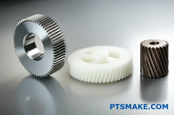
كيف تختار المادة المناسبة للعتاد؟
يعد اختيار مادة الترس المناسبة قرارًا حاسمًا. فهو يؤثر بشكل مباشر على الأداء والعمر الافتراضي والتكلفة الإجمالية لمنتجك. يجب أن تكون المتطلبات المحددة لتطبيقك هي التي توجه اختيارك.
فكر في عوامل مثل الحمل والسرعة والبيئة التشغيلية. إن الترس الفولاذي عالي العزم لناقل حركة السيارات له احتياجات مختلفة تمامًا عن الترس البلاستيكي منخفض الضوضاء داخل طابعة مكتبية.
إليك نظرة عامة سريعة للبدء:
| فئة المواد | الميزة الرئيسية | حالة الاستخدام الشائع |
|---|---|---|
| سبائك الصلب | قوة ومتانة عالية | ناقل الحركة في السيارات |
| بلاستيك | ضوضاء منخفضة ومقاومة للتآكل | المعدات المكتبية، الطبية |
| سبائك البرونز | انخفاض الاحتكاك والتوافق | محركات التروس الدودية |
سيساعدك هذا الدليل على التنقل بين هذه الخيارات لمشروعك.
دعنا نتعمق أكثر في دليل عملي لاختيار المواد. يوازن الخيار الأفضل دائمًا بين الأداء والميزانية. في PTSMAKE، نبدأ غالبًا بتحليل القوى التشغيلية والبيئة لإيجاد هذا التوازن.
سبائك الصلب للأعمال عالية الإجهاد
بالنسبة للقوة والمتانة العالية، فإن الفولاذ هو المادة المفضلة. فهو يتعامل مع الأحمال العالية والتآكل بشكل استثنائي، سواء للتروس المحفزة أو التروس الحلزونية. كما يمكن للمعالجة الحرارية أن تعزز خصائصه بشكل كبير.
| سبائك الصلب | الأفضل لـ | الميزة الرئيسية |
|---|---|---|
| فولاذ 4140 | عزم الدوران العالي والمتانة | القدرة على التصلب العابر |
| 8620 فولاذ | الصدمات وتآكل السطح | ممتازة لتقسية الحالة |
بلاستيك للتطبيقات المتخصصة
لا تستهين بالبلاستيك. فهي تحل المشكلات الشائعة مثل الضوضاء والتآكل والحاجة إلى التشحيم الخارجي. واستنادًا إلى اختباراتنا، فهي مثالية للتطبيقات ذات الأحمال الخفيفة حيث تكون هذه العوامل حرجة.
الفريدة من نوعها الخصائص القبلية18 من البلاستيك تجعلها ضرورية في العديد من التصميمات الحديثة.
خيارات البلاستيك الشائعة
- ديلرين (أسيتال): معروف باحتكاكه المنخفض وثبات أبعاده الممتاز. نوصي به للأجزاء المتحركة الدقيقة.
- نايلون: يوفر صلابة ومقاومة جيدة للمواد الكيميائية. كما أنها رائعة في إخماد الضوضاء والاهتزازات.
برونز للتزاوج منخفض الاحتكاك
السبائك البرونزية هي خيار كلاسيكي لأنواع معينة من التروس. وهي شائعة بشكل خاص للعجلات الدودية التي تتزاوج مع الديدان الفولاذية. يوفر هذا الزوج من المواد احتكاكًا منخفضًا للغاية ويمنع التآكل تحت الأحمال الثقيلة.
اختيار مادة الترس المناسبة هو مفاضلة. يوفر الفولاذ قوة للأحمال العالية. يوفر البلاستيك عملية هادئة ومقاومة للتآكل للمهام الأخف. ويتفوق البرونز في تطبيقات محددة منخفضة الاحتكاك. المفتاح هو مطابقة المادة مع المتطلبات الفريدة للتطبيق الخاص بك.
كيف يمكنك إعادة تصميم محرك ترس محفز صاخب من أجل الهدوء؟
يعد محرك التروس المحفزة الصاخبة تحديًا هندسيًا شائعًا. وغالباً ما يتضمن الحل الأكثر فعالية إعادة تصميم كامل. لا يكفي تبديل الأجزاء ببساطة.
نستبدل التروس المحفزة المزعجة بتروس حلزونية. يقلل هذا التغيير من الضوضاء بشكل كبير. ومع ذلك، فإنه يتطلب إعادة تصميم دقيق للنظام بأكمله.
المفتاح هو فهم الاختلافات بين التروس المحفزة والتروس الحلزونية. فالأسنان ذات الزوايا في التروس الحلزونية تتشابك تدريجياً، وهذا هو السبب في أنها تعمل بهدوء أكثر.
| نوع العتاد | الخطوبة | مستوى الضوضاء |
|---|---|---|
| ترس محفز | مفاجئ | عالية |
| ترس حلزوني | تدريجي | منخفضة |
تتضمن إعادة التصميم هذه تعديلات في الهندسة والمحامل والمبيت.
عندما نعيد تصميم محرك الأقراص لتحقيق الهدوء، فإننا نتجاوز مجرد تبديل بسيط للتروس. الانتقال من التروس المحفزة إلى التروس الحلزونية هو تغيير هندسي أساسي. فهو يؤثر على التجميع الميكانيكي بأكمله.
إعادة حساب هندسة التروس
الخطوة الأولى هي إعادة حساب هندسة الترس. إدخال الزاوية الحلزونية يغير كل شيء. فهو يخلق تعشيق أسنان أكثر سلاسة وتدرجاً. وهذا هو السبب الرئيسي لتقليل الضوضاء. يجب علينا ضبط زاوية الضغط ومظهر السن لتحسين التلامس وتقليل التآكل.
تحديد مواصفات المحامل الجديدة
تولد التروس المحفزة في المقام الأول أحمالاً شعاعية. وتنتج التروس الحلزونية، بسبب أسنانها ذات الزوايا، أحمالًا شعاعية و الدفع المحوري19. يجب إدارة هذه القوة الجديدة. قد تفشل المحامل الكروية القياسية. يجب أن نحدد المحامل القادرة على التعامل مع أحمال الدفع، مثل المحامل الأسطوانية المخروطية أو محامل التلامس الزاوي.
تعديل السكن
تتطلب المحامل وقوى الدفع الجديدة تعديلات على المبيت. يجب أن يكون المبيت صلبًا بما يكفي لدعم ترتيب المحامل الجديد. يجب أن يمنع أي انحراف للعمود تحت الحمل. في شركة PTSMAKE، غالبًا ما نعيد تصميم المبيت لضمان المحاذاة الدقيقة والموثوقية على المدى الطويل.
| جانب التصميم | محرك التروس المحفزة | إعادة تصميم التروس الحلزونية |
|---|---|---|
| الحِمل الأساسي | شعاعي | شعاعي ومحوري |
| نوع المحمل | محمل كروي بسيط | تلامس مدبب/زاوي |
| الإسكان | الصلابة القياسية | معزز للدفع |
| الضوضاء | عالية | منخفضة |
التحول إلى التروس الحلزونية للتشغيل الهادئ ليس مجرد استبدال. إنها عملية إعادة تصميم شاملة تتضمن هندسة جديدة، ومحامل متخصصة للتعامل مع الدفع، ومبيت معدّل. وهذا يضمن نظاماً هادئاً وموثوقاً حقاً.
كيف يمكنك تحسين تصميم الترس لتحقيق الحد الأدنى من الوزن؟
بالنسبة للتطبيقات الحرجة مثل الطيران، كل غرام مهم. الاستراتيجيات المتقدمة ضرورية. نحن نتجاوز التصميم الأساسي لتحقيق الحد الأدنى من الوزن.
مواد عالية الأداء
يعد اختيار مواد مثل سبائك الصلب عالية القوة أو التيتانيوم الخطوة الأولى. فهي توفر نسب قوة إلى وزن فائقة.
المعالجات الحرارية المتقدمة
عمليات مثل الصقل بالنترة أو الكربنة تصلب سطح الترس. وهذا يزيد من سعة التحميل. ويسمح ذلك بترس أصغر وأخف وزنًا للقيام بنفس المهمة.
تحسين فراغات العتاد الفارغة
تُعدّ عملية تنجيد فراغ الترس تقنية أساسية. نقوم بإزالة المواد من جسم الترس بشكل استراتيجي. يقلل ذلك من الوزن دون التأثير على منطقة الأسنان الحرجة.
| الاستراتيجية | التأثير على الوزن | النظر في |
|---|---|---|
| المواد المتقدمة | عالية | ارتفاع تكلفة المواد |
| المعالجة الحرارية | متوسط | خطوة عملية إضافية |
| حزام الويب | عالية | التصنيع الآلي المعقد |
يتطلب تحسين الوزن المتقدم نهجاً شاملاً. ويتعلق الأمر بالجمع بين علم المواد والمعالجة الحرارية والتصميم الهندسي الذكي لإنشاء ترس قوي وخفيف الوزن بشكل لا يصدق.
تحسين الهيكل الأساسي للعتاد
إن تجزئة التروس الفارغة هو فن أكثر منه علم. فهو ينطوي على تشكيل جيوب من المواد من القرص المركزي للترس. وهذا يزيل الكتلة غير الأساسية. والهدف من ذلك هو إنشاء هيكل شبيه بالقضبان أو هيكل شبكي. وهذا يحافظ على الصلابة مع تقليل الوزن بشكل كبير. في المشاريع السابقة في PTSMAKE، حققنا تخفيضاً كبيراً في الوزن بهذه الطريقة.
| نوع العتاد | الوزن النسبي | التعقيد |
|---|---|---|
| سوليد فارغ | 100% | منخفضة |
| شبكة فارغة مغطاة | 60-75% | عالية |
شكل الأسنان وقوتها
وبعيداً عن الفراغ، تُعد التعديلات على شكل الأسنان أمراً بالغ الأهمية. تعديل دقيق مثل إضافة تتويج20 يمكن أن يضمن توزيع الحمل بالتساوي عبر وجه السن، حتى في ظل المحاذاة الخاطئة الطفيفة. وهذا يمنع تركزات الضغط في أطراف الأسنان.
هذا التوزيع المحسّن للحمل يعني أن الترس يمكنه تحمل المزيد من الضغط. لذلك، يمكننا تصميمه ليكون أصغر وأخف وزنًا من البداية. هذا المبدأ هو أحد الاعتبارات الرئيسية في النقاش حول التروس المحفزة مقابل التروس الحلزونية، حيث يستجيب كل نوع بشكل مختلف لمثل هذه التعديلات. إن إقران هذه التعديلات في التصميم مع المواد الفائقة والمعالجات الحرارية هي الطريقة التي نقدم بها تروساً خفيفة الوزن من الدرجة الأولى للصناعات التي تتطلب الكثير من المتطلبات.
يتضمن التحسين لتحقيق الحد الأدنى من الوزن استخدام مواد عالية القوة ومعالجات حرارية متقدمة. ويؤدي التصميم الذكي، مثل تجزئة التروس الفارغة وتعديل شكل السن، إلى إزالة الكتلة غير الضرورية دون المساس بسلامة هيكلية الترس أو أدائه.
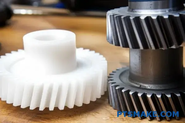
متى تختار عمداً ترساً محفزاً بلاستيكياً بدلاً من الفولاذ؟
من السهل الاعتقاد بأن الفولاذ أفضل دائماً. فهو أقوى، أليس كذلك؟ ولكن القوة ليست العامل الوحيد. بالنسبة للعديد من التطبيقات، فإن التروس المحفزة البلاستيكية هي الخيار الأكثر ذكاءً وكفاءة.
هذا صحيح بشكل خاص عندما تتغير الأولويات. فكر في الضوضاء المنخفضة أو التشحيم الذاتي أو مقاومة التآكل. في هذه الحالات، غالبًا ما يتفوق البلاستيك على المعدن. التكلفة هي أيضًا محرك رئيسي.
| الميزة | ميزة العتاد البلاستيكي | ميزة التروس الفولاذية |
|---|---|---|
| الضوضاء | منخفضة جداً | يمكن أن تكون عالية |
| التشحيم | تشحيم ذاتي | يتطلب مادة تشحيم خارجية |
| التكلفة | أقل، خاصة في الأحجام الكبيرة | ارتفاع تكلفة المواد والتصنيع الآلي |
| الوزن | خفيف الوزن | ثقيل |
ما وراء القوة الغاشمة: الخيارات الخاصة بالتطبيق
في عملنا في PTSMAKE، نوجه العملاء بشأن اختيار المواد. يتعلق الأمر بمطابقة المواد مع بيئة العالم الحقيقي. القوة البحتة غالبًا ما تكون مبالغة.
الإلكترونيات المكتبية والاستهلاكية
ضع في اعتبارك طابعة أو ماسح ضوئي. هذه الأجهزة موجودة في المكاتب أو المنازل. يجب أن تعمل بهدوء. التروس الفولاذية ستصدر الكثير من الضوضاء.
التروس المحفزة البلاستيكية مثالية هنا. فهي تعمل بصمت تقريباً. كما أنها لا تحتاج إلى الشحوم التي قد تلطخ الورق أو تتلف الإلكترونيات. كما أنها ممتازة الخصائص القبلية21 ضمان عمر طويل بدون صيانة.
البيئات ذات مخاطر التآكل
ماذا عن الجهاز المستخدم بالقرب من الماء أو المواد الكيميائية؟ قد تصدأ التروس الفولاذية وتتعطل بسرعة. الفولاذ المقاوم للصدأ خيار متاح، لكنه باهظ الثمن.
التروس البلاستيكية محصنة بشكل طبيعي ضد التآكل. وهذا يجعلها مثالية لمعدات تجهيز الأغذية أو الأجهزة الطبية أو المنتجات الخارجية. فهي توفر أداءً موثوقًا حيث لا يستطيع الفولاذ ذلك. عند مقارنة التروس المحفزة مقابل التروس الحلزونية لهذه الاستخدامات، غالبًا ما تكون المادة أكثر أهمية من نوع التروس لطول العمر.
| مجال التطبيق | الفوائد الرئيسية للبلاستيك |
|---|---|
| الطابعات المكتبية | ضجيج منخفض، لا حاجة للتشحيم |
| الأجهزة الطبية | قابل للتعقيم، ومقاوم للتآكل |
| تجهيز الأغذية | مقاومة للمواد الكيميائية، لا تلوث |
| الألعاب والأدوات | منخفضة التكلفة وخفيفة الوزن وآمنة |
باختصار، إن اختيار البلاستيك بدلاً من الفولاذ لا يتعلق بالمساومة. إنه قرار استراتيجي. فهو يعطي الأولوية للفعالية من حيث التكلفة، والضوضاء المنخفضة، والتشغيل بدون صيانة في التطبيقات التي لا يكون فيها عزم الدوران العالي والقوة الشديدة من المتطلبات الأساسية.
تحليل تأثير استبدال ترس محفز بترس حلزوني على الكفاءة.
من الشائع الاعتقاد بأن التشغيل الأكثر سلاسة يساوي كفاءة أعلى. ولكن في المناظرة بين التروس المحفزة مقابل التروس الحلزونية، ليس هذا هو الحال دائماً.
في حين أن التروس الحلزونية توفر تعشيقاً أكثر هدوءاً وتدرجاً، فإن أسنانها ذات الزوايا تقدم ديناميكية فريدة من نوعها. وهذا يغير القوى المؤثرة.
مصدر عدم الكفاءة
يعود الفرق الأساسي إلى نوع التلامس بين الأسنان. وهذه نقطة دقيقة ولكنها حاسمة بالنسبة لأي مهندس تصميم.
| نوع العتاد | حركة الاتصال الأساسية | النتيجة |
|---|---|---|
| ترس محفز | التدحرج/الانزلاق | النقل المباشر للطاقة |
| ترس حلزوني | زيادة الانزلاق | أكثر سلاسة، ولكن أكثر احتكاكاً |
هذه الحركة الانزلاقية المتزايدة على طول وجه السن هي المفتاح. يولد احتكاكاً وحرارة أكثر قليلاً مقارنةً بالترس المحفز.
نظرة أعمق على الاحتكاك والقوى
دعونا نحلل هذه المفاضلة. تتشابك أسنان الترس المحفّز بحركة متدحرجة إلى حد كبير، مع بعض الانزلاق. هذه طريقة فعالة للغاية لنقل الطاقة.
تحتوي التروس الحلزونية، بسبب زاويتها الحلزونية، على أسنان تنزلق في التعشيق. هذا التلامس الانزلاقي المستمر يقلل من الضوضاء وأحمال الصدمات، وهي ميزة كبيرة.
ومع ذلك، فإن حركة الانزلاق هذه تخلق احتكاكًا أكثر من التلامس المتداول في المقام الأول للتروس المحفزة. استنادًا إلى اختباراتنا الداخلية، يمكن أن يؤدي ذلك إلى خسارة طفيفة في الكفاءة، عادةً في نطاق 1-3%، اعتمادًا على التطبيق والتشحيم.
فهم المبادلات
يخلق التصميم الحلزوني أيضاً قوة موازية لمحور الترس. وهذا الدفع المحوري22 يجب إدارتها عن طريق المحامل المناسبة، والتي يمكن أن تقدم خسائر الاحتكاك الخاصة بها إلى النظام. الخيار ليس بسيطاً دائماً.
| الميزة | ترس محفز | ترس حلزوني |
|---|---|---|
| العملية | أعلى | أكثر هدوءاً وسلاسة |
| تلامس الأسنان | خط الاتصال | المشاركة التدريجية |
| الكفاءة | عالية جداً | أقل قليلاً |
| الحِمل المحوري | لا يوجد | نعم |
في PTSMAKE، غالبًا ما نعمل مع العملاء لتحليل هذه النقاط الدقيقة. يعتمد اختيار نوع الترس المناسب كليًا على الأولويات المحددة للتطبيق - سواء كان مستوى الضوضاء أو سعة التحميل أو الكفاءة القصوى.
توفر التروس الحلزونية أداءً أكثر سلاسة وهدوءاً. ولكن أسنانها المائلة تزيد من الاحتكاك المنزلق. ويؤدي ذلك إلى مفاضلة طفيفة، ولكنها مهمة، في الكفاءة مقارنة بحركة التدحرج المباشرة للتروس المحفزة.
احصل على حلول التروس المحفزة والحلزونية الخبيرة مع PTSMAKE
هل أنت مستعد لحلول التروس الدقيقة؟ كن شريكًا مع PTSMAKE للحصول على التروس المحفزة والحلزونية المخصصة والمصممة وفقًا لمعاييرك الصارمة. أرسل طلب عرض الأسعار الخاص بك الآن واستمتع بالتواصل الموثوق به والتفاوتات الصارمة والمهل الزمنية السريعة والالتزام الحقيقي بنجاحك.

افهم الدور الحاسم الذي تلعبه هذه الدائرة في تحديد شكل السن الملتوية بالكامل. ↩
تعلّم كيفية إدارة هذه القوة للحصول على التصميم الأمثل لنظام التروس وطول العمر الافتراضي. ↩
تعرّف على كيفية تأثير هذه الميزة الهندسية الهامة على توزيع القوة وكفاءة التروس. ↩
استكشف الغوص بشكل أعمق في كيفية اندماج متجهات القوى المختلفة في أنظمة التروس. ↩
راجع دليلنا التفصيلي لفهم كيفية تأثير هندسة التروس على الأداء. ↩
فهم كيفية تأثير هذه الخاصية الميكانيكية على مستويات الاهتزاز والضوضاء في أنظمة التروس. ↩
استكشف كيف يضمن خط التلامس التدريجي على الأسنان الحلزونية نقل أكثر سلاسة وهدوءاً للطاقة. ↩
افهم كيف تؤثر هذه القوة على تصميم التروس وما هي المحامل اللازمة لإدارتها بفعالية. ↩
فهم كيف يمكن لتحليل الإجهاد السطحي أن يمنع تعطل التروس قبل الأوان. ↩
فهم كيفية تأثير هذه القوة على تصميم التروس واختيار المحامل المناسبة. ↩
تعرّف على كيفية تأثير هذه القوة على تصميم التروس وطول عمرها. ↩
استكشف كيف تستخدم هذه المضخات ميكانيكا التروس الدقيقة لنقل السوائل بدقة استثنائية. ↩
تعلم كيفية حساب هذه القوة وإدارتها في تصميماتك. ↩
اكتشف كيف تمنع هذه الإضافات الكيميائية تعطل التروس الكارثي في ظل الأحمال القصوى. ↩
تعرف على كيفية تأثير تركيز الإجهاد على إجهاد المواد والعمر الافتراضي للمكونات. ↩
فهم كيفية تأثير هذه القوى المتغيرة على طول عمر الترس وأداء النظام. ↩
تعرّف على المزيد حول رد الفعل العكسي للتروس وكيفية تقليلها إلى الحد الأدنى لتطبيقات التصنيع الآلي باستخدام الحاسب الآلي عالي الدقة. ↩
تعرّف على كيفية تحديد خصائص الاحتكاك والتآكل والتشحيم التي تحدد أداء تروسك وعمرها الافتراضي. ↩
افهم كيف تؤثر هذه القوة على تصميم التروس واختيار المحامل لتحقيق الأداء الأمثل. ↩
اكتشف كيف يمكن لهذا التعديل الدقيق في الأسنان أن يحسّن بشكل كبير من تشبيك التروس ويطيل العمر التشغيلي. ↩
تعرف على المزيد حول كيفية تأثير الاحتكاك والتآكل والتشحيم على أداء مواد التروس. ↩
فهم كيفية تأثير هذه القوة على اختيار المحمل وتصميم النظام. ↩