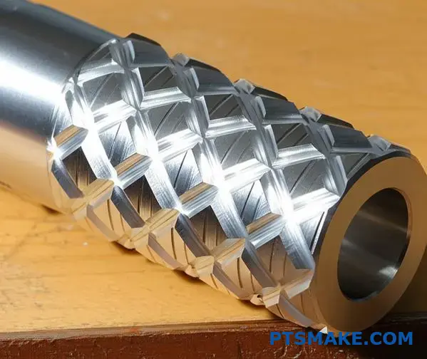
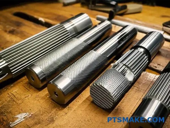
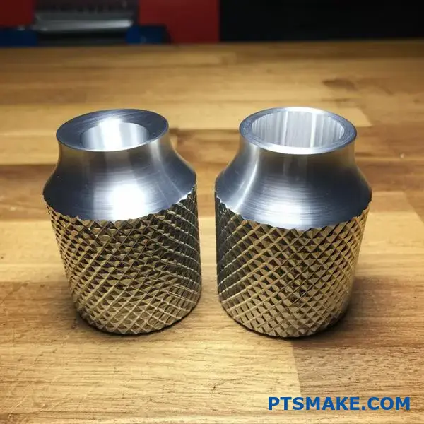
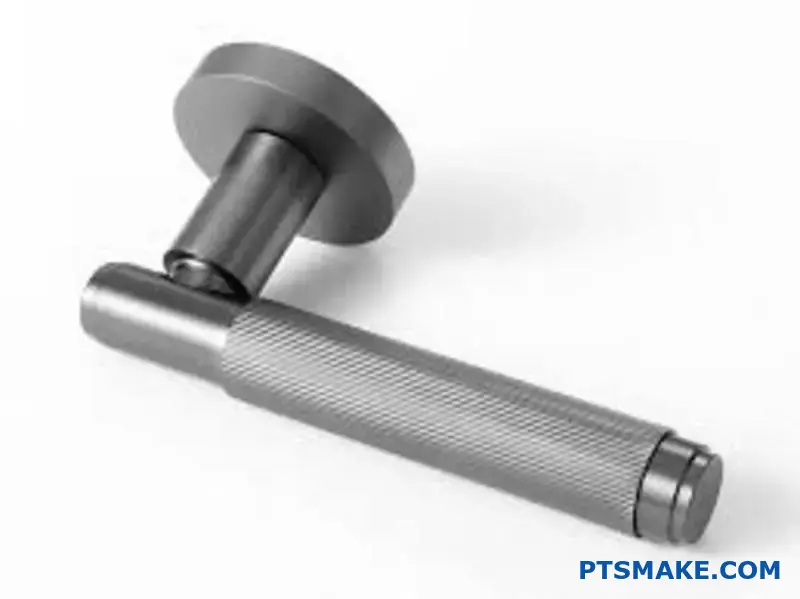
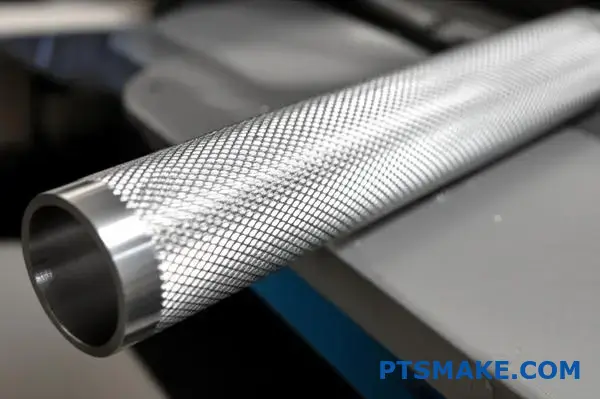
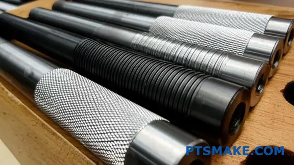
Getting consistent, professional-looking knurling patterns remains one of the most challenging aspects of precision machining. Many manufacturers struggle with pattern doubling, uneven depth, and tracking issues that result in costly rework and rejected parts.
Knurling patterns are defined by mathematical variables including pitch, helix angle, tooth geometry, and depth, with success depending on proper tool selection, workpiece diameter calculations, and understanding the relationship between these parameters for specific applications.
Through my work at PTSMAKE, I’ve helped clients solve complex knurling challenges across automotive, medical, and consumer electronics applications. This guide covers the fundamental principles, classification systems, and advanced techniques that separate professional-grade knurling from amateur results.
What fundamental variables define any knurling pattern mathematically?
Knurling patterns may seem complex. However, they are built on a few core mathematical variables. Understanding these fundamentals is key. It allows us to control the final texture with precision.
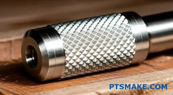
The Four Pillars of Knurling
These variables dictate everything from grip to appearance. They form the basis for consistent and repeatable results on any part.
Key Knurling Parameters
| Variable | Description |
|---|---|
| Pitch | The distance between consecutive teeth. |
| Angle | The angle of the grooves relative to the workpiece axis. |
| Depth | How deep the teeth are pressed into the material. |
| Tooth Profile | The shape of an individual tooth (e.g., sharp, rounded). |
These four elements work together. They create the complete geometric definition of any knurl.
Beyond the Basics: The Synergy of Variables
Defining a knurl isn’t just about listing variables. It’s about understanding how they interact. This synergy is where true precision manufacturing lies. At PTSMAKE, we focus on mastering these interactions for every project.
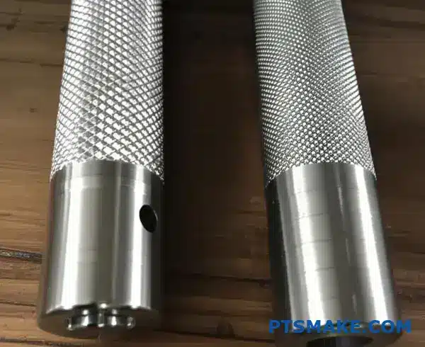
Pitch and Angle Interaction
The pitch sets the density of the pattern. A finer pitch means more teeth per inch. The angle determines if the pattern is straight (0°), angled, or a diamond (e.g., 30° left and right helices). These two define the fundamental look.
The Functional Roles of Depth and Profile
Depth and tooth profile control the function. Deeper knurls offer a more aggressive grip. A sharper tooth profile also enhances grip but can be abrasive. Rounded profiles are often used for a comfortable, decorative finish. This choice directly impacts the user’s tactile experience with the final product.
The industry often standardizes these using a system called diametral pitch1. This ensures that tools and the resulting knurling patterns are consistent across different manufacturing setups.
Impact of Variable Adjustment
| Adjustment | Resulting Knurl Characteristic |
|---|---|
| Increase Pitch | Coarser, wider-spaced pattern |
| Decrease Pitch | Finer, denser pattern |
| Increase Depth | More aggressive grip, higher material displacement |
| Sharpen Profile | Better grip, potentially more abrasive |
Ultimately, a complete mathematical model requires all four of these variables for a predictable outcome.
In short, just four key variables—pitch, angle, depth, and tooth profile—provide the complete mathematical blueprint for any knurling pattern, dictating its final appearance and functional grip.
What is the rationale behind knurling standards like DIN 82?
Before standards, knurling was a wild west. Results were inconsistent. One shop’s "medium" knurl was another’s "coarse." This caused major issues in assembly and grip functionality.
The Rise of Standardization
Standards like DIN 82 brought order. They created a shared language for engineers, designers, and machinists. Everyone knew the exact requirements.
This ensures that a part designed in Germany can be flawlessly manufactured by us at PTSMAKE and fit perfectly into an assembly in the USA.
| Problem Without Standards | Solution with DIN 82 |
|---|---|
| Unpredictable Grip Force | Consistent Functional Texture |
| Part Mating Failures | Guaranteed Dimensional Accuracy |
| High Manufacturing Waste | Efficient and Repeatable Processes |
The engineering logic behind DIN 82 is rooted in functionality and manufacturability. It’s not arbitrary. The standard codifies parameters that directly impact performance.
Decoding Key Parameters
Details like pitch, tooth angle, and depth are specified for a reason. A deeper knurl provides a stronger grip for hand tools. A finer pitch might be used for a delicate adjustment knob.
The standard defines various knurling patterns to suit different needs. This moves beyond a simple "diamond" or "straight" description. It offers precise classifications.
| DIN 82 Code | Knurl Pattern | Primary Function |
|---|---|---|
| RAA | Straight (Axial) | Basic grip, decorative finish |
| RGE | Male Diamond (30°) | High-torque grip applications |
| RGV | Male Diamond (45°) | General-purpose gripping surfaces |
These codes eliminate guesswork. When we receive a drawing specifying "RGE 0.8," our team knows the exact tool and process needed. This precision is built on the standard’s geometric rules.
The standard’s module2 system is fundamental here. It dictates the relationship between the tool and workpiece diameter, ensuring a clean and complete pattern without overlaps or partial teeth. This prevents material deformation and ensures a high-quality finish.
Knurling standards like DIN 82 establish a clear framework. They transform an imprecise art into a repeatable science, defining specific knurling patterns and parameters. This guarantees functional consistency and manufacturing predictability, which is crucial for modern high-precision industries.
What constitutes ‘surface integrity’ for a knurled component?
Evaluating a knurled surface isn’t just about looks. True quality is defined by a set of clear metrics. At PTSMAKE, we go beyond a simple visual check.
We focus on a comprehensive evaluation. This ensures the component performs reliably under stress. The integrity of the surface is critical.
Key Quality Metrics
Here are the core areas we assess:
- Surface Finish: Smoothness and consistency.
- Micro-Cracks: Tiny fractures that compromise strength.
- Metallurgical Changes: Alterations in the material’s structure.
| Metric | Importance | Common Issue |
|---|---|---|
| Surface Finish | High | Inconsistent grip, poor aesthetics |
| Micro-Cracks | Critical | Component failure under load |
| Metallurgical Changes | High | Reduced fatigue life, brittleness |
These factors together determine the true surface integrity of the part.
A Deeper Look at Evaluation
A truly comprehensive quality assessment uses specific tools and methods. It’s about seeing what the naked eye can’t.
Surface Finish (Ra)
We measure surface roughness (Ra) to ensure it meets specifications. This guarantees consistent grip and feel. Different knurling patterns require different Ra values for optimal function.
Microstructural Analysis
Detecting micro-cracks often requires microscopy. These tiny fissures are a primary cause of premature failure. They form during the high-pressure knurling process if parameters are not perfectly controlled.
Material Properties
The knurling process is a form of cold working. This can induce beneficial work hardening3, but overdoing it can cause issues. We analyze the material’s grain structure to confirm its integrity. This prevents brittleness and ensures long-term durability.
In our collaboration with clients, we’ve found that a balanced approach is key.
| Evaluation Method | Target Metric | Purpose |
|---|---|---|
| Profilometer | Surface Finish (Ra) | Quantify roughness and consistency |
| Dye Penetrant Test | Micro-Cracks | Reveal surface-breaking defects |
| Metallography | Metallurgical Changes | Examine grain structure and hardness |
This multi-pronged approach ensures every knurled component we produce is fit for its intended purpose.
A thorough evaluation of a knurled surface requires more than a visual inspection. It involves precise measurements of surface finish, detailed checks for micro-cracks, and an analysis of the underlying metallurgical changes to guarantee performance and reliability.
What is the fundamental design principle making knurling aesthetically pleasing?
Why do we find knurling so appealing? It’s more than just a functional grip. The beauty lies at the intersection of precision engineering and human psychology. Our brains are wired to appreciate order and detail.
The Power of Patterns
Knurling patterns tap into this preference. The regularity of the diamonds or lines creates a sense of predictability and control. This visual harmony is inherently satisfying. It signals careful manufacturing and attention to detail.
Texture and Light
The texture invites touch, creating a tangible connection. Light reflects off the facets, adding depth and a dynamic quality that flat surfaces lack.
| Design Element | Psychological Effect |
|---|---|
| Pattern Regularity | Signals order and precision |
| Tactile Texture | Encourages physical interaction |
| Light Reflection | Creates visual depth and interest |
Engineering Meets Human Perception
The aesthetic success of knurling patterns is not accidental. It is a calculated result of how our minds process sensory information. The consistent, repeating geometry speaks a language of reliability and structure that we instinctively trust.
The Critical Role of Touch
The tactile sensation of a knurled surface is crucial. This engagement is a form of haptic perception4 that provides immediate feedback about the object’s quality. A sharp, clean knurl feels secure and well-made. A poorly executed one feels cheap and unreliable. At PTSMAKE, we machine our knurls to exact specifications. This ensures they not only look good but also feel right, reinforcing the user’s confidence in the product.
How Light Defines Quality
The way light plays across a knurled surface is also key. The tiny, angled faces create a complex matrix of highlights and shadows. This effect makes the part look more intricate and valuable. It transforms a simple cylinder into an object of perceived craftsmanship.
| Sensory Input | Design Detail | User Perception |
|---|---|---|
| Visual | Precise Light & Shadow Play | High Value, Intricacy |
| Tactile | Sharp, Uniform Ridges | Reliability, Durability |
| Cognitive | Repetitive, Orderly Pattern | Quality Craftsmanship |
Knurling’s aesthetic appeal comes from a masterful blend of engineering and psychology. The structured patterns, engaging texture, and dynamic light reflection all signal precision and quality. This makes the design both functionally effective and visually satisfying.
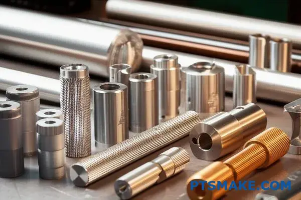
What are the primary categories of knurling patterns beyond geometry?
Beyond simple shapes, we can classify knurling patterns in more practical ways. This helps in choosing the right pattern for the job.
We can look at function, like how it grips. We can also consider the manufacturing process.
Finally, how the material reacts is key. These categories offer a smarter way to think about knurling patterns. They help ensure the final part performs exactly as needed for its specific application.
Functional Classification
| Function Type | Primary Goal | Common Application |
|---|---|---|
| Grip Enhancement | Increase friction for manual handling | Tool handles, knobs, fasteners |
| Press-Fit Aid | Securely join two components | Shafts, pins, inserts |
| Fluid Channeling | Direct or retain liquids/lubricants | Sealing surfaces, bearing races |
Manufacturing Process Classification
We can also group patterns by how they are made. The two main methods are cutting and forming. Each process creates a distinct result and suits different materials and applications.
Material Response Classification
How a material behaves during knurling also creates a category. Softer metals deform differently than harder ones, impacting the final texture and performance of the knurled surface.
At PTSMAKE, we guide clients by looking beyond geometry. Focusing on function, process, and material response leads to better part performance. This practical approach avoids costly mistakes.
Function-Based Categories
Thinking about the job a knurl needs to do is often the best starting point. Is it for grip, for a tight fit, or something else entirely?
| Category | Description |
|---|---|
| Grip Knurling | The most common type. Its purpose is purely to provide a secure, non-slip surface for hands or tools. |
| Press-Fit Knurling | This knurling is designed to slightly increase a part’s diameter. It creates a strong interference fit when pressed into another component. |
| Decorative Knurling | Here, the focus is on aesthetics. The pattern adds a high-end, industrial look to a product. |
Process-Based Categories
The manufacturing method directly influences the knurling pattern’s characteristics. Cut knurling removes material, creating sharp, precise peaks. This is great for harder materials.
Roll forming, on the other hand, displaces material without creating chips. This process strengthens the surface through work hardening. The resulting peaks are smoother. Understanding the subtle changes caused by material displacement5 is crucial for high-tolerance applications.
Material Response Categories
Different materials react uniquely to knurling pressures. Soft materials like aluminum might flow easily, creating smooth, rounded profiles. Harder materials like stainless steel resist deformation. This can result in sharper, more defined patterns but also requires more force.
Choosing the wrong pattern for a material can lead to flaking or an inconsistent finish. This is why we always match the knurling strategy to the specific material properties.
Thinking about knurling through function, process, and material response provides a deeper understanding. This approach moves beyond simple looks, ensuring the knurling pattern serves its true engineering purpose effectively and reliably for the intended application.
How can knurling patterns be classified by their functional application?
Knurling patterns are not just for show. Their true value is in their function. We can classify them based on what they’re designed to do. This helps engineers select the right pattern for the job.
You wouldn’t use a delicate pattern for a high-torque tool. Let’s break down these functional groups. Each one serves a distinct purpose in product design.
| Functional Category | Primary Purpose |
|---|---|
| High-Torque Grip | To increase friction for handling. |
| Tactile Feedback | To signal function to the user. |
| Fluid Retention | To hold or channel liquids. |
| Decorative Finishes | For purely aesthetic enhancement. |
| Interference Fit | To create a secure mechanical bond. |
Understanding knurling starts with its intended job. A pattern’s effectiveness is tied directly to its application. This is a core principle we follow at PTSMAKE on every project.
High-Torque Grip Applications
For tools or parts requiring a strong, non-slip grip, an aggressive pattern is essential. Diamond knurling is a common choice here. It provides maximum friction for hand tools, heavy knobs, and industrial equipment handles. The goal is pure function over form.
Delicate Tactile Feedback
Some applications don’t need a powerful grip. Instead, they need to provide subtle feedback to the user. Think of precision adjustment knobs on scientific instruments. Fine, straight knurling patterns work well here. They offer just enough texture to feel, ensuring precise control.
Fluid Retention and Management
Certain knurling patterns can hold lubricants. Recessed diamond or square patterns create small pockets. These pockets use capillary action6 to retain oil or grease. This is useful for self-lubricating bushings or shafts.
Decorative Finishes
Sometimes, the primary function is aesthetic. On high-end products like watch crowns or premium electronic dials, knurling adds a touch of elegance. The focus here is on flawless execution and visual appeal.
| Feature | High-Torque Grip Knurl | Decorative Knurl |
|---|---|---|
| Pattern Depth | Deep and aggressive | Shallow and precise |
| Primary Goal | Maximize friction | Visual appeal, clean lines |
| Example | Wrench handle | Watch crown |
Interference Fit Applications
Knurling can also create a mechanical bond. By displacing material, a knurled shaft can create a tight press-fit into a hole. This method is often more cost-effective than other fastening techniques for permanent assemblies.
Understanding the functional application is key. Whether for high-torque grips, fluid retention, or a secure interference fit, the right knurling pattern optimizes performance. The function always dictates the form in precision manufacturing.
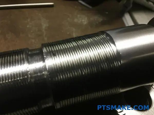
What is a systematic classification of knurling failure modes?
Recognizing knurling failure modes is the first step toward fixing them. Each defect tells a story about what went wrong during the manufacturing process.
Understanding these visual cues helps us quickly identify the root cause. This prevents wasted time and material. Below is a quick guide to common issues.
| Defect Type | Primary Indication |
|---|---|
| Flaking | Material or Tool Issue |
| Doubling | Setup or Alignment Error |
| Uneven Depth | Inconsistent Pressure/Feed |
| Barreling | Excessive Force |
These knurling patterns signal specific problems, making troubleshooting much more efficient.
Linking Defects to Root Causes
In our projects at PTSMAKE, we’ve developed a systematic approach to diagnosing these failures. It’s about looking at the evidence and working backward to find the source.
Flaking and Chipping
Flaking occurs when small pieces of metal break away from the knurl crests. This often points to a worn or chipped knurling tool. It can also mean the material is too brittle for the process. Our analysis shows certain steel alloys are more prone to this.
Doubling or "Ghosting"
This defect creates a second, faint pattern overlapping the primary one. It’s almost always a setup issue. The culprit is often a lack of rigidity in the machine or workpiece holder. It can also be caused by incorrect tool alignment with the workpiece centerline.
Uneven Depth and Inconsistent Patterns
When the knurl depth varies, look at pressure and feed rate. An inconsistent feed can cause the tool to bite deeper in some areas. Also, check for workpiece runout. A non-concentric part will naturally lead to an uneven finish. The material’s reaction to the tool pressure, influenced by factors like Work hardening7, also plays a role.
The table below connects these issues to solutions.
| Failure Mode | Common Root Cause | Recommended Solution |
|---|---|---|
| Doubling | Machine or tool misalignment | Re-align tool to workpiece centerline |
| Barreling | Excessive side pressure | Reduce pressure; check tool wear |
| Uneven Depth | Inconsistent feed rate | Ensure constant feed; check for runout |
| Flaking | Brittle material; worn tool | Change material or tool; adjust speed |
By categorizing these common defects, we turn troubleshooting from guesswork into a science. Linking each failure mode to its likely process or setup cause allows for faster, more effective solutions, ensuring consistent quality in every part we produce.
How do materials group for optimal knurling process selection?
Selecting the right knurling process starts with understanding the material. Different materials react differently to the intense pressure of knurling. At PTSMAKE, we simplify this by grouping materials based on their core properties.
This approach helps predict how a material will behave. It ensures we choose a method that delivers a clean, functional knurl without damaging the part.
Key Material Properties for Knurling
We primarily look at three things: ductility, hardness, and the tendency to work-harden. These factors dictate whether forming or cutting is the better option.
| Property | Description | Impact on Knurling |
|---|---|---|
| Ductility | Ability to deform without fracturing | High ductility is ideal for form knurling. |
| Hardness | Resistance to plastic deformation | Hard materials often require cut knurling. |
| Work-Hardening | Hardening due to plastic deformation | High tendency requires careful process control. |
Group 1: Soft and Ductile Metals
This group includes materials like aluminum, brass, and low-carbon steels. Their high ductility and lower hardness make them perfect candidates for form knurling. The metal flows easily into the knurling tool’s teeth.
This process displaces material rather than removing it. It creates a strong, raised pattern with a smooth finish. We often use this for parts that require a good grip without sharp edges.
Group 2: Hard and Less Ductile Metals
Materials like stainless steel and alloy steels fall here. Their higher hardness and tendency to work-hardening8 present a challenge. Applying the pressure of form knurling can make these materials even harder, leading to tool wear or a poor finish.
For these, cut knurling is usually the superior choice. This method uses sharp-edged wheels to machine the pattern into the workpiece. It removes material, creating precise, sharp knurling patterns without inducing excessive stress in the material.
Group 3: Plastics
Plastics such as Delrin (POM) or Nylon behave very differently. Their low melting points and elasticity mean heat management is critical. Cut knurling is almost always the required method for thermoplastics. It minimizes heat buildup and prevents the material from melting or gumming up the tool.
| Material Group | Common Materials | Recommended Process | Key Consideration |
|---|---|---|---|
| Soft & Ductile | Aluminum, Brass, Mild Steel | Form Knurling | Excellent for creating smooth, raised patterns. |
| Hard & Tough | Stainless Steel, Alloy Steel | Cut Knurling | Avoids excessive work-hardening and tool wear. |
| Plastics | Delrin (POM), Nylon, ABS | Cut Knurling | Requires sharp tools and heat control. |
Grouping materials this way provides a solid foundation for process selection. It moves us from guesswork to a data-driven decision, ensuring consistent quality for every project we handle at PTSMAKE.
Understanding material groups is key to selecting the right knurling process. This approach ensures a predictable, high-quality finish by matching the material’s properties with the most suitable method, whether it’s forming, cutting, or a specialized technique for plastics.
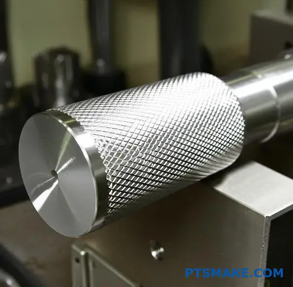
What are the structural differences between micro and macro knurling?
The shift from millimeter to micron scale transforms knurling. Macro knurling is about creating a rough, tactile surface for grip. It’s a familiar process.
Micro-knurling, however, operates on a completely different level. It engineers surfaces with precise, functional features. This requires advanced manufacturing techniques and tools.
Here’s a quick comparison.
| Feature | Macro Knurling (Millimeter Scale) | Micro Knurling (Micron Scale) |
|---|---|---|
| Primary Process | Forming or Cutting | Laser Ablation, Etching, Micro-Machining |
| Tooling | Hardened Steel Wheels | Diamond Tips, Laser Beams, Etchants |
| Functional Goal | Mechanical Grip, Aesthetics | Fluid Dynamics, Adhesion, Optical |
The differences in these knurling patterns are fundamental.
Moving from macro to micro-scale manufacturing changes everything. For traditional knurling, we use hardened steel tools to displace or cut material on a lathe. It’s a robust and relatively straightforward process focused on creating a grip pattern.
Micro-knurling is far more delicate. In our projects at PTSMAKE, we often employ methods like laser ablation or ultra-precision CNC machining. These techniques remove material with microscopic accuracy rather than displacing it. This precision is crucial for controlling the surface’s tribological properties9, affecting friction and fluid flow.
The tooling requirements also reflect this difference in scale. A standard knurling tool is durable and simple. For micro-applications, we might use a diamond-tipped stylus or a highly focused laser. The control systems must manage movements on a sub-micron level.
This table highlights the challenges.
| Challenge | Macro Knurling | Micro Knurling |
|---|---|---|
| Material Behavior | Predictable plastic deformation | Unpredictable; grain structure matters |
| Tool Wear | Gradual and easy to monitor | Rapid and catastrophic; requires fine control |
| Quality Control | Visual inspection, calipers | SEM, profilometers, advanced imaging |
Functional applications diverge widely. Macro knurling patterns enhance grip on tool handles or knobs. Micro-knurled surfaces are found in medical implants to encourage cell growth or in microfluidic devices to direct liquid flow.
Ultimately, the scale dictates the entire manufacturing approach. Macro knurling is for human interaction and grip. Micro-knurling is for engineering functional surfaces where performance is measured at a microscopic level, demanding far greater precision and investment.
What defines the system of convex versus concave knurling applications?
Applying knurls to curved surfaces is not a one-size-fits-all process. The geometry, whether convex or concave, completely changes the game.
A convex surface curves outward, like a doorknob. A concave surface curves inward, like the inside of a bowl. Each presents unique challenges. This dictates tool choice, setup, and the final quality.
Convex vs. Concave Basics
| Feature | Convex Knurling | Concave Knurling |
|---|---|---|
| Surface Shape | Outwardly curved | Inwardly curved |
| Tool Contact | Consistent | Varies significantly |
| Common Use | Grips, knobs, dials | Custom fittings, decorative rings |
| Difficulty | Lower | Higher |
Understanding these differences is key to success.
The main distinction lies in tool engagement. On convex surfaces, standard knurling wheels can maintain consistent contact. The tool presses into the material evenly as the part rotates. This creates a uniform pattern with relative ease.
Concave surfaces are much trickier. A standard tool will only contact the surface at its highest points. This results in an incomplete or distorted pattern. The risk of toolpath interference10 is also significantly higher. The tool holder could collide with the part’s edges.
Navigating Geometric Challenges
At PTSMAKE, we often tackle these complex geometries. For concave knurling, we sometimes need custom-ground knurling wheels. These wheels match the workpiece’s inner curve. This ensures full contact and a clean pattern.
Specialized tool holders with specific angles are also essential. They provide the necessary clearance to avoid collisions. This approach requires careful programming and setup.
| Challenge | Convex Solution | Concave Solution |
|---|---|---|
| Uneven Pressure | Standard setup | Custom tool profiles |
| Incomplete Pattern | Not a typical issue | Matched-radius wheels |
| Tool Collision | Low risk | Angled holders, careful programming |
Based on our test results, a well-planned concave knurling operation can add significant value. But it demands expertise.
In short, while convex knurling is relatively straightforward, concave applications require specialized tooling and careful planning. The geometry of the curve is the single most important factor in determining the right approach and ensuring high-quality knurling patterns.
What are the defining characteristics of hybrid or composite patterns?
When standard knurls don’t meet a design’s needs, we explore hybrid patterns. These are custom designs that break the mold.
They move beyond simple straight or diamond knurls. It’s about creative engineering.
Combining Knurl Elements
We often mix different knurling styles. For example, combining straight and helical lines. This creates unique textures and functional grips. Varying the pitch within one pattern is another advanced technique.
Hybrid Pattern Examples
| Feature Combination | Primary Benefit | Common Application |
|---|---|---|
| Straight + Helical | Multi-directional grip | Custom tool handles |
| Variable Pitch | Targeted texture feel | Ergonomic grips |
| Interrupted Diamond | Reduced material stress | Thin-walled components |
This approach allows for truly bespoke knurling patterns.
Engineering Custom Solutions
Hybrid knurls are not just for looks. They solve specific engineering challenges. A product might need a strong grip in one direction but a smooth feel in another. This is where custom patterns shine.
At PTSMAKE, we use advanced CNC machining for these tasks. Creating a non-standard knurl requires precise tool path programming. Standard tools often cannot produce these complex geometries.
The Manufacturing Process
We begin by modeling the pattern in CAD software. This helps us visualize the final texture. Then, our engineers develop a custom machining strategy.
This might involve multiple passes with different tools. It could also mean creating a custom form tool. The goal is to achieve the exact grip and aesthetic the client specified. This process ensures the part’s properties are not uniform but anisotropic11, tailored for specific functions.
| Challenge | Our Solution at PTSMAKE |
|---|---|
| Complex Geometry | Advanced 5-axis CNC programming |
| Tooling Limitations | Custom tool design and fabrication |
| Consistency Issues | In-process quality control checks |
This careful approach makes complex knurling patterns achievable.
Hybrid knurls blend different design elements. This creates unique functional and aesthetic properties. While challenging to machine, they offer tailored solutions for specific product requirements, demanding advanced CNC machining expertise and careful planning to execute successfully.
What is the structural relationship between pitch and workpiece diameter?
In knurling, ‘tracking’ is everything. It ensures the tool re-engages the same grooves on each rotation. This creates a clean, uniform pattern.
Poor tracking results in a messy, overlapping finish. This not only looks bad but also compromises the grip function of the knurl. It’s a detail we never overlook.
Why Tracking Matters
Proper tracking is the foundation of high-quality knurling patterns. It requires precise setup and calculation.
| Tracking Status | Pattern Outcome | Functionality |
|---|---|---|
| Good | Clean, uniform grooves | Excellent grip |
| Bad | Overlapping, messy | Poor grip, looks unprofessional |
Achieving this perfect alignment is a core part of our process at PTSMAKE.
To achieve perfect tracking, the workpiece diameter must be a near-multiple of the circular pitch. This mathematical relationship is non-negotiable for a professional finish. It ensures the teeth of the knurling tool mesh perfectly with the grooves they create on every single revolution of the part.
The Math Behind the Match
Think of it like gears meshing. If the teeth don’t align, the system fails. The same principle applies here. An incorrect diameter causes the tool to cut new, shallow grooves over the old ones. This is often called "double-tracking" or "flaking."
At PTSMAKE, we calculate the ideal blank diameter before any machining begins. This prevents defects and ensures the final knurling patterns meet exact specifications. A slight adjustment to the pre-knurl diameter often makes all the difference.
Diameter and Pitch Harmony
The relationship ensures a clean pattern. We calculate the circumference and divide it by the tool’s circular pitch12. The result should be a whole number, or very close to it.
| Component | Role in Calculation | Desired Outcome |
|---|---|---|
| Workpiece Diameter | Determines the circumference | A near-multiple of the pitch |
| Circular Pitch | The distance between teeth | Divides evenly into circumference |
| Result | An integer (whole number) | Perfect, repeatable pattern |
This precision ensures the knurled surface is both functional and aesthetically pleasing. It is a critical step in our quality control process for every project involving knurls.
For clean knurling patterns, the workpiece diameter must align with the tool’s circular pitch. This ensures the tool tracks correctly on each rotation, avoiding messy, overlapping grooves and guaranteeing a functional, professional finish.
How are custom knurling patterns specified for manufacturing?
Communicating a non-standard knurling pattern requires more than a simple note. An engineering drawing is your primary tool. It must be unambiguous.
Without clear details, machinists are left to guess. This leads to errors and costly rework. The key is providing a complete set of specifications that leaves no room for interpretation. Custom knurling patterns demand this level of precision from the start.
Essential Drawing Information
A detailed drawing acts as a contract between the designer and the machinist. For custom patterns, this contract needs specific clauses.
| Standard Callout | Custom Specification |
|---|---|
| Knurl Type | Custom Pattern Geometry |
| Pitch | Tooth Profile, Angle, Depth |
| Diameter | Pre/Post Knurl Diameters |
This clarity ensures the final part matches your exact vision.
To avoid ambiguity, your engineering drawing must be a complete guide. It should detail every aspect of the custom knurling pattern. This ensures the machinist can produce exactly what you designed without any guesswork. At PTSMAKE, we always stress the importance of comprehensive drawings.
Geometric Pattern Definition
First, define the pattern’s geometry. This includes the tooth profile shape, such as v-shaped, rounded, or a unique form. Specify the exact tooth angle, depth, and the pitch (TPI or circular pitch).
Tool and Process Notes
Specify the required knurling tool if you have a specific one in mind. Note the material and hardness of the part. This helps the machinist select the right parameters. For example, forming knurls behave differently than cutting knurls.
Critical Dimensions and Tolerances
Clearly state the major diameter after knurling. Include acceptable tolerances. Providing both pre-knurl and post-knurl diameters is best practice. This controls the material displacement. Precise metrology13 is essential for verifying these final dimensions.
| Parameter | Specification Example |
|---|---|
| Tooth Profile | Custom Convex, R0.2mm |
| Included Angle | 105° +/- 1° |
| Knurl Depth | 0.35mm REF |
| Post-Knurl Ø | 25.4mm +0.00/-0.15 |
| Surface Finish | Ra 1.6 µm max |
These details create a complete picture for manufacturing.
An unambiguous engineering drawing is non-negotiable for custom knurling. It must clearly define pattern geometry, tool requirements, and final dimensions with tolerances. This detail is the foundation for producing a successful part that meets your exact design intent.
How do you adapt knurling techniques for thin-walled or delicate parts?
Knurling thin-walled parts is a delicate balance. Too much pressure can easily cause distortion or collapse. The key is to support the part and control the force.
We must shift from brute force to a more strategic approach. This involves specialized tools and careful setup. It ensures the integrity of the delicate workpiece.
Key Prevention Strategies
- Use specialized tools: Scissor-style tools are essential.
- Provide internal support: Mandrels prevent walls from collapsing.
- Control the pressure: Gradual application is critical.
A comparison highlights the necessary adjustments.
| Feature | Standard Knurling | Adapted Technique |
|---|---|---|
| Tool Type | Standard holder | Scissor-style |
| Support | Often none | Internal mandrel |
| Pressure | High, quick | Low, gradual |
Preventing part distortion requires a fundamental change in how we apply knurling pressure. Standard knurling tools push from one side, putting immense stress on the part. This is where specialized techniques come into play.
Using Scissor-Style Tools
Scissor-style knurling tools are a game-changer for delicate parts. They use two opposing wheels that "pinch" the workpiece. This applies equal pressure from both sides simultaneously.
The forces effectively cancel each other out. This minimizes stress on the part and the machine’s spindle bearings. It’s a technique we often recommend at PTSMAKE for hollow or thin components.
The Role of Internal Support
For hollow parts, an internal support mandrel is non-negotiable. This mandrel is inserted into the part before knurling. It provides a rigid backbone, counteracting the external pressure.
The mandrel prevents the thin walls from collapsing or warping under force. Without this support, maintaining dimensional accuracy and preventing deformation14 is nearly impossible. Different knurling patterns might require slight adjustments to the support.
Careful Pressure Control
Controlling application pressure is the final piece of the puzzle. We never apply full pressure at once. Instead, we use a gradual, multi-pass approach.
This allows the material to flow into the knurl teeth without being overworked. Modern CNC controls are great for this, enabling precise, repeatable pressure settings for each pass.
| Step | Action | Purpose |
|---|---|---|
| 1. Setup | Insert support mandrel | Provide internal rigidity |
| 2. Tooling | Use a scissor-style tool | Balance knurling forces |
| 3. First Pass | Apply very light pressure | Establish the pattern |
| 4. Subsequent Passes | Gradually increase pressure | Deepen the knurl gently |
| 5. Inspection | Check for distortion | Ensure part integrity |
Knurling delicate parts successfully depends on preventing distortion. Key methods include using scissor-style tools to balance forces, internal mandrels for support, and carefully controlled pressure. These techniques are crucial for maintaining the part’s structural integrity and achieving high-quality results.
How would you design a knurl pattern for medical implant integration?
When designing for medical implants, the surface is everything. It’s not just about mechanical grip. It’s about encouraging the body to accept and merge with the device.
We must apply principles of biocompatibility and osseointegration. The right knurling pattern creates a scaffold. This scaffold promotes bone growth, securing the device permanently.
Key Design Principles
| Principle | Design Goal | Knurl Feature |
|---|---|---|
| Biocompatibility | Prevent adverse reactions | Material choice, clean surface |
| Osseointegration | Promote bone in-growth | Controlled surface roughness |
Engineering Surfaces for Cellular Response
The surface texture of an implant sends signals to the body’s cells. Our goal is to create a welcoming environment. We want to encourage bone-forming cells, known as osteoblasts15, to attach, grow, and multiply on the implant surface.
Optimizing Surface Roughness
A surface that is too smooth won’t provide enough grip for cells. However, a surface that is too rough can damage them. It’s a delicate balance. In our experience, a controlled, specific range of surface roughness offers the best foundation for cell adhesion and proliferation.
The Role of Geometry
The geometry of the knurling patterns is also critical. Features like micro-grooves and cavities provide protected spaces. These areas allow new bone to grow into the implant, creating a strong mechanical lock. This interlocking is the key to achieving long-term stability and preventing implant loosening over time.
| Knurl Feature | Biological Impact |
|---|---|
| Micro-Pits & Pores | Increase surface area for cell attachment. |
| Sharp Corners | Should be avoided; they can cause stress and damage cells. |
| Interlocking Channels | Provide pathways for bone to grow into. |
Designing a knurl pattern for a medical implant is a biological challenge. The surface must be precisely engineered to encourage osseointegration. This ensures the device becomes a stable, integrated part of the body for the best patient outcome.
How can knurling be used as a primary element in luxury design?
Knurling does more than provide grip. In luxury goods, it becomes a central aesthetic. This detail transforms ordinary objects into premium experiences.
It communicates quality through touch and sight. Let’s look at how this works in different products. The right knurling patterns can define a brand’s identity.
| Product Category | Functional Role | Aesthetic Contribution |
|---|---|---|
| Watches | Grip on Crown/Bezel | Signals Mechanical Precision |
| Writing Instruments | Secure Grip | Adds Weight & Tactile Richness |
| Audio Equipment | Knob Adjustment | Suggests Pro-Grade Durability |
This texture signals superior craftsmanship. It tells a story of quality before the product is even used.
The Watchmaker’s Signature
On a luxury watch, the knurled crown is iconic. It’s the primary point of interaction. The crisp, precise texture communicates the quality of the mechanism inside. It’s a small detail that speaks volumes about heritage and engineering.
In past projects at PTSMAKE, we’ve machined similar features. Achieving that perfect, uniform pattern requires immense precision. This detail truly elevates the entire timepiece from a simple accessory to a piece of art.
The Writer’s Companion
Premium pens often use knurling on the grip. This adds a reassuring weight and balance. The texture makes the act of writing feel more intentional and significant. The tactile sensation enhances the overall haptic feedback16.
This connection turns a simple tool into a valued personal item. It’s a subtle cue that signals thoughtful design and high-quality materials, making the user experience much more engaging.
The Audiophile’s Interface
Consider high-end audio equipment. The volume and tuning knobs frequently feature distinct knurling. This design choice is often inspired by professional studio gear, implying superior performance and durability. It provides a satisfying, controlled feel with each adjustment.
| Case Study | Primary Knurled Component | Core Design Message |
|---|---|---|
| Luxury Watch | Crown and Bezel | Precision & Heritage |
| Executive Pen | Grip Section | Quality & Permanence |
| Hi-Fi Audio | Control Knobs | Professional & Reliable |
These case studies show how knurling moves beyond function. It becomes a signature detail that defines a product’s premium identity. It enhances the user experience by engaging both sight and touch, communicating quality in a powerful, non-verbal way.
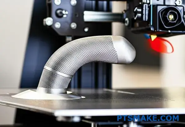
How can knurling be integrated with additive manufacturing processes?
Additive manufacturing (AM) completely changes how we think about knurling. It’s no longer a separate, secondary step. Instead, the texture is designed directly into the 3D model.
This integration opens up incredible design freedom. We are no longer limited by the physical constraints of cutting tools.
From Limitation to Imagination
Traditional methods confine knurls to simple surfaces. Additive manufacturing, however, allows us to apply complex knurling patterns to almost any shape you can imagine.
This direct-print approach saves time and removes process steps.
| Aspect | Traditional Knurling | AM-Integrated Knurling |
|---|---|---|
| Process | Secondary, post-machining | Integrated, single step |
| Geometry | Simple, external surfaces | Complex, internal surfaces |
| Complexity | Limited patterns | Virtually unlimited designs |
New Functional Possibilities
Imagine knurling inside a tube to improve fluid mixing. Or a grip pattern that perfectly follows an ergonomic, curved handle. These designs were once impossible. Now, they are achievable.
Designing for Unprecedented Complexity
With AM, the design possibilities for knurling patterns are nearly infinite. You are not choosing from a standard catalog. You are creating a unique feature tailored to your part’s exact needs.
This means we can move beyond simple diamond or straight knurls. We can design textures that serve highly specific functions.
Advanced Knurling Patterns
Consider a grip where the knurl is denser in certain areas for better control. Or a surface with a pattern that reduces aerodynamic drag. This level of customization is unique to additive processes.
In past projects with clients, we’ve used principles of generative design17 to develop these highly optimized textures. The software helps create patterns that are both functional and lightweight.
This approach lets us tailor textures for specific applications, enhancing performance in ways traditional methods cannot match.
| AM Knurling Technique | Primary Benefit | Example Application |
|---|---|---|
| Conformal Knurling | Follows complex curves perfectly | Ergonomic grips on custom tools |
| Variable-Density Knurling | Optimizes texture across a surface | High-friction zones on control knobs |
| Internal Knurling | Adds texture to inner surfaces | Static mixers in fluid pipes |
| Biomimetic Textures | Mimics natural patterns | Low-drag surfaces for aerospace parts |
A New Mindset for Engineers
This shift requires a new way of thinking. Engineers can now design for optimal performance without being constrained by manufacturing limitations. It merges texture and structure into one seamless element.
Additive manufacturing unlocks new possibilities for knurling. It allows for the direct integration of complex patterns on almost any surface, turning a simple texture into a highly engineered feature that enhances both function and performance.
When is knurling more cost-effective than other grip-enhancing techniques?
Choosing a grip is about more than feel. It’s a critical budget decision. Knurling is a classic choice, but is it always the cheapest?
We need to compare it to other methods. This includes overmolding, coatings, sandblasting, and laser etching.
Each has unique costs and benefits. The right choice depends on your production volume and design goals. Different knurling patterns also affect the final cost and function. Let’s break down the economics.
A true cost analysis looks beyond the per-unit price. You must consider tooling, setup, and production volume. In past projects at PTSMAKE, we’ve helped clients navigate this choice.
Knurling is often a one-time tooling setup. This makes it highly efficient for large production runs. The per-unit cost becomes very low as volume increases.
Other methods have different cost structures. Overmolding18 requires a second, more complex mold. This increases initial tooling costs significantly. However, it can create unique, high-value grips that combine hard and soft materials.
Coatings and sandblasting have lower setup costs. This makes them attractive for smaller batches. But their per-unit cost may not decrease as much with volume. Laser etching offers precision but can be slower, affecting cost on very large runs.
Here is a simplified cost-benefit comparison based on our experience:
| Technique | Initial Tooling Cost | Per-Unit Cost (High Vol.) | Durability | Best for Volume |
|---|---|---|---|---|
| Knurling | Medium | Very Low | Excellent | High |
| Overmolding | High | Medium | Very Good | Medium-High |
| Coatings | Low | Low-Medium | Varies | Low-Medium |
| Sandblasting | Very Low | Low | Good | All Volumes |
| Laser Etching | High (Machine) | Low | Excellent | Low-High |
This table helps guide the decision. The most cost-effective solution truly depends on your specific project requirements and scale.
In summary, knurling is often the most cost-effective choice for high-volume metal parts. For lower volumes or different materials, alternatives like sandblasting or coatings might be cheaper upfront. Your production scale is the key factor.
What is the future evolution of knurling technology and patterns?
Knurling is evolving far beyond a simple grip. We are entering an era of intelligent surfaces. Technologies like laser texturing and advanced algorithms are changing everything.
These methods create highly functional knurling patterns. They offer much more than just a better handle. The precision is on a completely new level.
| Feature | Traditional Knurling | Future Knurling |
|---|---|---|
| Method | Mechanical Deformation | Laser, Additive Mfg. |
| Precision | Macro-level | Micro/Nano-level |
| Function | Grip, Aesthetics | Grip, Fluidics, Optics |
| Design | Geometric | Algorithm-Generated |
This shift unlocks amazing new applications for industries.
Let’s explore these future trends more closely. The possibilities are truly exciting for manufacturing.
Laser-Based Texturing
Lasers offer incredible precision. We can now create micro-textures on a surface. This is not just for looks. These tiny patterns can manage friction or repel water.
In projects at PTSMAKE, we’ve seen how surface finish impacts performance. Laser texturing takes this control to a microscopic scale, opening doors for advanced applications in medical and aerospace fields.
Computer-Generated Patterns
Imagine knurling patterns designed by a computer. They are not limited by traditional tool paths or human creativity.
Using Generative design19, software can create patterns optimized for a specific task. This could be for better heat dissipation on an electronic part or improved airflow on a component. The result is a pattern that is both unique and highly effective.
New Functional Applications
The real game-changer is combining these technologies with smart materials. Think about a surface that changes its texture based on temperature or pressure.
Here are some potential applications we are discussing with clients.
| Technology | Potential Application | Industry Benefit |
|---|---|---|
| Laser Texturing | Biocompatible Medical Implants | Improved Patient Outcomes |
| Generative Patterns | Aerodynamic Surfaces | Increased Fuel Efficiency |
| Smart Materials | Adaptive-Grip Tool Handles | Enhanced Safety & Ergonomics |
This evolution transforms knurling from a simple feature into a core engineering component. It adds significant functional value to the final product.
The future of knurling technology is moving toward precision and function. Advanced methods like laser texturing and computer-generated patterns are creating surfaces with entirely new capabilities. These go far beyond traditional mechanical grip enhancement.
Unlock Precision Knurling Solutions with PTSMAKE Expertise
Ready to elevate your next project with expertly engineered knurling patterns? Contact PTSMAKE now for a fast, no-obligation quote. Our team delivers high-precision CNC machining and injection molding for all industries—ensuring your custom requirements and quality expectations are met, from prototype to production!

Discover how this standard helps achieve consistent knurling across different tools and machines. ↩
Learn how this key parameter defines knurl spacing and ensures tool compatibility for precision manufacturing. ↩
Learn how this property impacts the durability and performance of your knurled components. ↩
Discover how our sense of touch influences the perception of an object’s quality and value. ↩
Learn how material flow during knurling impacts part strength and final dimensions. ↩
Learn how surface properties influence fluid behavior in micro-scale engineering applications. ↩
Learn how metal properties change during knurling and affect final quality. ↩
Learn how this material property can impact your machining process and final part quality. ↩
Learn how surface textures influence friction, wear, and lubrication in mechanical systems. ↩
Learn more about avoiding tool collisions in complex CNC machining setups. ↩
Learn how direction-dependent properties can be engineered for advanced applications. ↩
Explore a detailed guide on how this metric impacts final part quality. ↩
Learn how precise measurement techniques ensure your custom patterns meet exact specifications. ↩
Understand the key differences between elastic and plastic deformation and how it impacts your part’s final integrity. ↩
Discover how these specialized cells build new bone, which is fundamental to successful implant integration. ↩
Explore how tactile sensations can directly influence a user’s perception of product quality and value. ↩
Learn how this design methodology can help create optimized, high-performance parts for your specific needs. ↩
Learn more about this two-step process for creating integrated, multi-material components. ↩
Explore how this AI-driven process creates optimal designs that are often impossible for humans to conceive. ↩