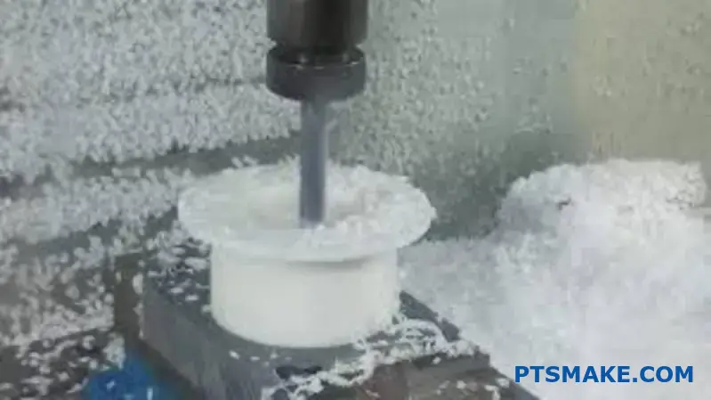
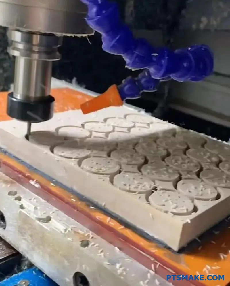
Many manufacturers struggle with PEEK machining, facing challenges like excessive tool wear, warped parts, and poor surface finishes. These issues stem from PEEK’s unique thermal properties and polymer behavior that differ drastically from traditional metals.
PEEK machining requires specialized techniques due to its low thermal conductivity, which traps heat at the cutting zone, and its polymer structure that demands sharp tools with positive rake angles rather than conventional metal-cutting approaches.
This comprehensive guide walks you through every aspect of PEEK machining, from material selection and tooling strategies to advanced troubleshooting techniques. You’ll discover proven methods that help you avoid common pitfalls and achieve consistent, high-quality results with this challenging engineering polymer.
What is PEEK’s most critical property affecting its machining?
When machining PEEK, many properties matter. But one stands out above all others. Its low thermal conductivity is the game-changer.
This property traps heat right at the cutting zone. Unlike metals, PEEK doesn’t dissipate this heat quickly.
Heat: The Primary Challenge
Managing this trapped heat becomes our number one priority. Effective PEEK machining depends on controlling temperature.
Below is a simple comparison to illustrate this point.
| Material | Thermal Conductivity (W/mK) |
|---|---|
| PEEK | 0.25 |
| Aluminum (6061) | 167 |
| Steel (Carbon) | 54 |
This difference completely changes our machining approach.
This low thermal conductivity creates a "heat trap" right where the cutting tool meets the material. The energy from cutting has nowhere to go. It builds up rapidly in a very small area.
For metals, this heat would quickly spread through the part and the tool. But with PEEK, it stays put. This localized heating can cause major problems.
Consequences of Trapped Heat
If the temperature gets too high, it can exceed PEEK’s glass transition temperature1. This softens the material, leading to a gummy consistency instead of a clean chip.
The results are poor surface finish and dimensional inaccuracy. The trapped heat also causes rapid tool wear. This forces us to adjust speeds, feeds, and cooling strategies constantly.
In past projects at PTSMAKE, we’ve seen how ignoring this property leads to failed parts. It can even induce internal stresses, compromising the part’s integrity long after machining is complete.
| Machining Issue | Root Cause (Related to Heat) |
|---|---|
| Gummy Chips | Localized melting |
| Poor Surface Finish | Material softening at tool tip |
| Rapid Tool Wear | Excessive heat on the cutting edge |
| Internal Stresses | Uneven heating and cooling |
Managing this single property is the key to high-quality PEEK parts.
PEEK’s low thermal conductivity is the most critical property affecting its machining. It traps heat at the cutting zone, making temperature control the primary challenge. Successful PEEK machining hinges on managing this heat to avoid material degradation and ensure part quality.
How does internal stress in PEEK blanks impact machining results?
PEEK blanks often contain hidden internal stress. This stress is a byproduct of the manufacturing process itself. Whether molded or extruded, uneven cooling locks tension within the material.
When we begin the PEEK machining process, this stored energy is released. This can cause significant problems. The part can warp, twist, or bend. This makes achieving tight tolerances very difficult. It’s a critical factor to manage.
| Stress Source | Primary Cause |
|---|---|
| Injection Molding | Rapid, uneven cooling |
| Extrusion | Frictional heat and cooling rates |
The Origin of Molded-In Stress
Internal stress is created when PEEK cools from a molten state. The outer surface of a blank cools and solidifies first. The core remains molten for longer.
As the core finally cools and shrinks, it pulls on the already rigid outer shell. This creates a state of tension inside the material. The forces are balanced as long as the blank is whole. This is a common form of residual stress2 in polymers.
How Machining Disrupts the Balance
The machining process systematically removes material. This removes the stressed outer layers that hold the internal forces in check.
With the outer "skin" gone, the internal tensile forces are no longer balanced. The material immediately begins to move or "relax" to find a new, stable state. This movement is what we see as warping or dimensional instability. In our projects at PTSMAKE, we have to account for this material behavior to ensure final part accuracy.
Consequences of Released Stress
The results of this stress release can be disastrous for a high-precision component.
- Warping: The part bends or twists out of its intended shape.
- Bowing: Flat surfaces become curved.
- Dimensional Instability: Tolerances are impossible to hold as the part changes shape post-machining.
This is a key challenge in PEEK machining.
Internal stress from molding or extrusion is a significant risk. Machining releases this stress, causing the PEEK part to warp and lose dimensional accuracy. This must be managed carefully to ensure the final component meets specifications.
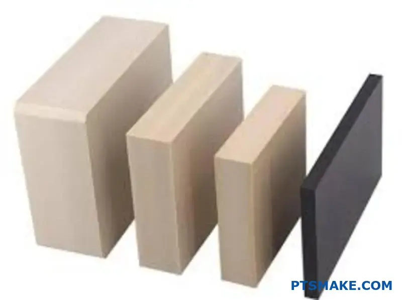
What defines a ‘machinable’ grade of PEEK material?
When we talk about PEEK, it’s not a one-size-fits-all material. The choice between unfilled (virgin) PEEK and filled grades is a crucial first step. Each has distinct machining characteristics.
Virgin PEEK is the purest form. It’s tough and has excellent chemical resistance.
Filled grades add materials like glass or carbon fibers. This boosts specific properties like stiffness or wear resistance. Choosing the right one depends entirely on the application’s demands.
| Grade | Key Advantage | Common Use Case |
|---|---|---|
| Unfilled (Virgin) | High purity, ductility | Medical implants, food processing |
| Glass-Filled | Increased stiffness, stability | Structural parts, insulators |
| Carbon-Filled | High strength, low friction | Bearings, aerospace components |
The Trade-Off: Strength vs. Abrasiveness
Adding fillers to PEEK is a bit like adding rebar to concrete. You gain significant strength and rigidity. This is fantastic for parts that need to withstand high loads or maintain tight tolerances under stress.
Glass-filled PEEK, for example, offers excellent dimensional stability. Carbon-filled PEEK provides superior strength-to-weight ratio and wear resistance. These enhancements make PEEK suitable for a wider range of demanding engineering applications.
However, these benefits come at a cost to machinability. The same hard fibers that provide strength are extremely abrasive. Machining filled PEEK is like cutting a fine-grit sandpaper. It wears down standard cutting tools very quickly. The orientation of these fibers can also create anisotropic3 properties.
This demands a different approach. At PTSMAKE, we switch to specialized tooling. Polycrystalline diamond (PCD) or diamond-coated carbide tools are often necessary for effective PEEK machining, especially for filled grades, ensuring both precision and reasonable tool life.
| Factor | Unfilled (Virgin) PEEK | Filled PEEK (Glass/Carbon) |
|---|---|---|
| Tool Wear | Moderate | Very High |
| Required Tooling | Carbide is effective | PCD or Diamond-Coated |
| Stiffness | Good | Excellent |
| Machining Strategy | More forgiving | Requires adjusted speeds/feeds |
Filled PEEK grades provide superior mechanical properties for demanding applications. However, their abrasive nature is a critical factor in PEEK machining, necessitating advanced tooling and specific machining strategies to maintain precision and manage costs effectively.
What is the primary cause of machining-induced defects in PEEK?
If I had to name one single culprit for defects in PEEK machining, it would be excessive heat. It’s the root cause of nearly every common issue we encounter.
PEEK doesn’t dissipate heat well. This low thermal conductivity means heat concentrates right at the cutting zone.
The Domino Effect of Heat
This buildup leads to a cascade of problems. The material can melt, chips become gummy, and the surface finish suffers dramatically. Excessive burring is another direct result.
Here’s a quick breakdown:
| Cause | Direct Effect | Resulting Defect |
|---|---|---|
| Excessive Heat | Material Softening & Melting | Gummy Chips, Burrs |
| Trapped Heat | Inconsistent Cutting | Poor Surface Finish |
| High Temp | Molecular Damage | Weakened Part |
Controlling temperature isn’t just a suggestion; it is the most critical factor for success.
Heat is more than just a surface-level nuisance. It can fundamentally alter the material itself, leading to part failure down the line. This is where understanding the material’s properties is key.
Every plastic has a point where it transitions from a rigid, glassy state to a softer, rubbery one. Exceeding PEEK’s glass transition temperature4 during machining is where major issues begin.
Beyond Melting: Thermal Degradation
When temperatures get too high, you’re not just melting the PEEK. You risk thermal degradation. This process breaks down the polymer chains, permanently damaging the material’s excellent mechanical and chemical properties. A part might look acceptable but be significantly weaker.
From Heat to Visible Flaws
At PTSMAKE, our process control focuses heavily on thermal management. We’ve found that this prevents the most common defects before they can even form.
Here’s how heat creates specific flaws:
| Heat-Induced Issue | Consequence on Machining |
|---|---|
| Gummy Chip Formation | Softened material sticks to the cutting tool, causing buildup. |
| Excessive Burring | Melted PEEK re-solidifies unevenly along part edges. |
| Poor Surface Finish | Tool galling and inconsistent material removal create a rough surface. |
Effectively managing heat is the core principle of high-quality PEEK machining.
In short, uncontrolled heat is the primary cause of PEEK machining defects. It leads to melting, burring, and poor finishes, and can even degrade the material’s core properties. Effective thermal management is therefore non-negotiable for producing reliable parts.
What fundamentally differentiates PEEK cutting from metal cutting?
The way a material forms chips tells you everything. It is the fundamental difference in the cutting process.
Metal: A Clean Shear
Metals like aluminum or steel fracture cleanly. The cutting tool creates a distinct shear plane. This results in well-defined, often segmented chips. The process is predictable.
PEEK: A Plastic Flow
PEEK behaves differently. As a polymer, it tends to flow or "plow" ahead of the tool. It doesn’t shear cleanly. This creates long, continuous, and often gummy chips.
This table shows the basic chip differences:
| Feature | Metal Cutting | PEEK Cutting |
|---|---|---|
| Mechanism | Shearing | Plowing / Flowing |
| Chip Type | Segmented, Brittle | Continuous, Gummy |
| Tool Edge | Sharpness is key | Extreme sharpness is critical |
The Science Behind the Chip
When cutting metal, the material ahead of the tool experiences intense stress. It shears off along a well-defined plane. This action creates predictable, manageable chips. The process is a classic example of brittle or controlled fracture.
PEEK machining is a different story. Its long-chain polymer structure resists clean shearing. Instead, the material deforms plastically. The tool pushes material ahead of it before it finally separates. This "plowing" action generates significant heat.
This type of material separation is a form of ductile fracture5. The material stretches and deforms extensively before it finally breaks away from the workpiece.
The Tooling Solution
To counter this, we need a different approach. Extremely sharp cutting edges are non-negotiable. At PTSMAKE, we use tools with very high positive rake angles. This helps lift the chip away and encourages a shearing action rather than plowing. It’s about coaxing PEEK to act more like metal.
This table contrasts typical tool geometry:
| Tool Geometry | Standard Metal | PEEK Machining |
|---|---|---|
| Rake Angle | Neutral to slightly positive | High positive (+15° or more) |
| Relief Angle | Standard (5-10°) | Higher (10-15°) |
| Edge Sharpness | Sharp | Extremely sharp, honed edge |
Without these specific geometries, you risk melting the material, poor surface finish, and high tool wear. It’s a challenge we’ve refined solutions for through many projects.
The core difference lies in chip formation. Metals shear into segmented chips. PEEK plows and flows, creating continuous, gummy chips. This requires extremely sharp tools with high rake angles to achieve a clean cut and avoid material melting.
What are the key failure modes in PEEK machining?
Understanding failure modes is critical for successful PEEK machining. Problems typically fall into three distinct categories. Each one signals an issue with the process.
We can group these failures as thermal, mechanical, and dimensional.
Common Failure Categories
Recognizing these issues early saves time and material. It is the first step toward process optimization.
| Failure Type | Key Issues | Primary Cause |
|---|---|---|
| Thermal | Melting, Charring | Excessive Heat |
| Mechanical | Cracking, Chipping | Improper Forces |
| Dimensional | Warping, Heavy Burrs | Material Stress |
Controlling these is key to producing quality parts.
A Deeper Look at Failure Modes
Let’s explore what these failures look like. In our projects at PTSMAKE, we’ve developed methods to identify and prevent them. Each category has unique signs.
Thermal Degradation
Heat is the biggest challenge in PEEK machining. If not managed, it leads to irreversible damage.
- Melting: PEEK’s high melting point can be misleading. Localized heat from friction can easily cause melting. This results in a poor surface finish.
- Charring: This is a clear sign of overheating. The material discolors and becomes brittle. It severely compromises the part’s structural integrity.
Mechanical Damage
This happens when cutting forces are too high or applied incorrectly. It leads to visible defects on the part.
| Mechanical Failure | Description | Common Cause |
|---|---|---|
| Cracking/Chipping | Small fractures on part surfaces or edges. | Aggressive cutting parameters, tool vibration. |
| Delamination | Layer separation in reinforced PEEK grades. | Wrong tool geometry, excessive feed rate. |
We sometimes see delamination6 when working with glass or carbon-filled PEEK. The bond between the polymer matrix and the fibers breaks down, which weakens the component significantly.
Dimensional Inaccuracy
A part can look good but still be out of spec. Dimensional failures are often the costliest.
Warping is a major issue. Internal material stresses are released unevenly during machining. This causes the part to twist. Heavy burrs are also common. They require careful, often manual, secondary operations to remove.
Understanding these failure modes is crucial. Thermal, mechanical, and dimensional issues can ruin any project. Recognizing the signs of melting, cracking, or warping allows for proactive adjustments. This ensures the final PEEK part meets all specifications.
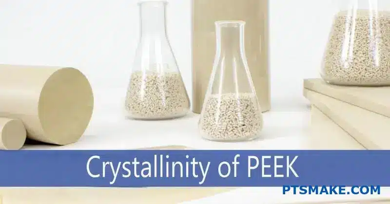
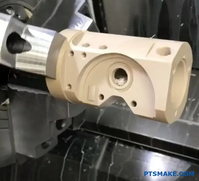
What is the role of crystallinity in PEEK machinability?
The structure of PEEK greatly affects how it behaves during machining. It exists in two main states: amorphous and semi-crystalline.
Think of amorphous PEEK as disorganized. Its molecular chains are random. This makes it softer and less stable.
Semi-crystalline PEEK is different. Its structure is highly ordered. This order brings hardness, strength, and stability. For PEEK machining, this is exactly what we want.
Amorphous vs. Semi-Crystalline PEEK
| Property | Amorphous PEEK | Semi-Crystalline PEEK |
|---|---|---|
| Structure | Disordered | Ordered, Crystalline |
| Appearance | Transparent, Amber | Opaque, Tan |
| Hardness | Softer | Harder |
| Stability | Less Stable | More Stable |
A consistent, high level of crystallinity is the goal for predictable results.
To achieve the best machinability, we rely on a process called annealing. This heat treatment process transforms PEEK’s internal structure. It encourages the molecular chains to align into an ordered, crystalline state.
At PTSMAKE, we often anneal PEEK stock shapes before any machining begins. This crucial step relieves internal stresses from the manufacturing process. It also raises the material’s crystallinity to a consistent, optimal level.
Why does this matter? An annealed, semi-crystalline PEEK is much more stable. It doesn’t deform as easily under the heat and pressure of cutting tools. This stability is critical when holding tight tolerances.
The material’s behavior also changes above its glass transition temperature7. A higher crystallinity ensures the material remains rigid and predictable during the PEEK machining process, preventing gummy or melted cuts.
Benefits of Annealing for PEEK Machining
| Feature | Benefit |
|---|---|
| Higher Hardness | Cleaner cuts, better chip formation. |
| Increased Stability | Maintains shape, holds tighter tolerances. |
| Stress Relief | Prevents warping after machining. |
| Predictability | Consistent material response to tools. |
In our experience, properly annealed PEEK is the foundation for successful high-precision parts. It turns a challenging material into a predictable one, allowing for faster cycle times and superior surface finishes. This control is non-negotiable for demanding applications.
Controlling crystallinity through annealing is key. It makes PEEK harder, more dimensionally stable, and predictable to machine. This ensures we can consistently deliver high-precision components that meet exact specifications for every project.
What defines an ‘ideal’ chip when machining PEEK material?
When machining PEEK, the chips are your best feedback. They tell you if your process is right.
An ideal chip is a direct sign of a healthy cut.
Chip Shape and Form
You want to see distinct, individual pieces. Long, stringy ribbons are a red flag. They indicate too much heat buildup or incorrect tool geometry.
Chip Color and Texture
The color should be a clean, light tan. Dark, burnt, or melted chips mean the cutting temperature is too high. This damages the PEEK material’s integrity.
A good PEEK chip tells a clear story.
| Characteristic | Ideal Chip (Good) | Problem Chip (Bad) |
|---|---|---|
| Shape | Short, distinct, segmented | Long, stringy, continuous |
| Color | Light tan or natural | Dark brown, black, burnt |
| Texture | Clean, crisp | Melted, gummy, smeared |

Reading the Signs: What Chips Tell Us
The visual state of a PEEK chip is not just about aesthetics. It is a real-time diagnostic tool for the entire PEEK machining process. Each chip provides immediate insight into the cutting zone.
The Problem with Stringy Chips
Long, continuous chips are problematic. They can wrap around the tool and workpiece. This leads to poor surface finish and can even cause tool breakage. It often signals that the feed rate is too low or the cutting edge isn’t sharp enough. This creates more friction than actual cutting.
The Danger of Discoloration
Dark or burnt chips are a critical warning. PEEK has a high melting point, but excessive heat can cause thermal degradation. This process alters the material’s molecular structure. It can change it to an amorphous state8, weakening the final part. The goal is to shear the material cleanly, not melt it away. At PTSMAKE, we train our operators to constantly monitor chip color. This ensures the material’s properties are preserved.
| Chip Issue | Potential Cause | Recommended Action |
|---|---|---|
| Long, Stringy Chips | Feed rate too low; dull tool | Increase feed rate; use a sharper tool |
| Dark/Burnt Chips | Spindle speed too high; poor cooling | Reduce spindle speed; improve coolant flow |
| Melted/Gummy Chips | Incorrect tool geometry; excessive heat | Use tools designed for plastics; check all cutting parameters |
In summary, ideal PEEK chips are short, segmented, and light-colored. These characteristics indicate that cutting parameters are optimized, preventing material damage and ensuring a high-quality finished part. This is key for successful PEEK machining.
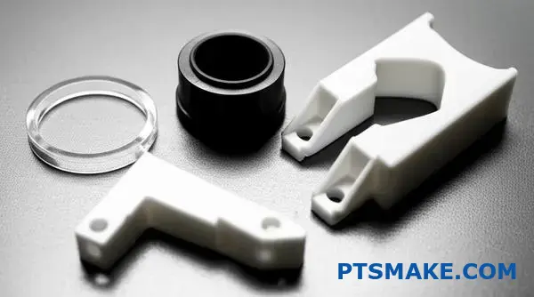
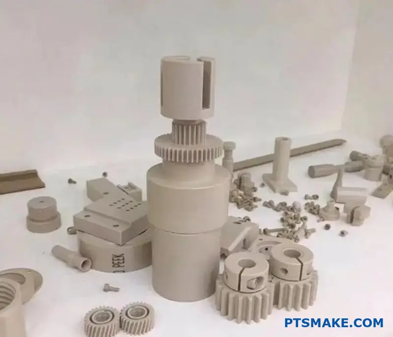
What are the main categories of PEEK material grades?
PEEK is not a one-size-fits-all material. Its true power lies in its different grades. Each grade is engineered for very specific performance requirements.
We can group them into four main categories. This classification makes it much easier to select the right material for your design.
The Four Core PEEK Families
| Grade Category | Key Characteristic | Common Use Case |
|---|---|---|
| Unfilled | High Purity & Ductility | Seals, Bushings |
| Bearing | Low Friction & Wear | Bearings, Thrust Washers |
| Reinforced | High Strength & Stiffness | Structural Components |
| Specialty | Unique Properties | Medical Implants |
Understanding these groups is the first step in successful PEEK part design.
Let’s dive deeper into each grade. Knowing the specific differences is crucial for both performance and manufacturability. This choice affects everything down the line.
Unfilled Grades (Natural PEEK)
This is the purest form of PEEK. It offers the highest elongation and toughness of all grades. We often use it for seals, insulators, and backup rings. Its natural abrasion resistance and purity are key benefits.
Bearing Grades (Low-Friction)
These are compound materials. PEEK is blended with solid lubricants like carbon fiber, PTFE, and graphite. This mix dramatically reduces friction and improves wear resistance. They are perfect for parts that move against each other without external lubrication.
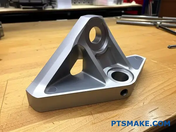
Reinforced Grades (High-Strength)
For high-load structural parts, reinforced grades are necessary. Adding glass or carbon fibers boosts mechanical strength and stiffness.
| Property | PEEK-GF30 (Glass-Filled) | PEEK-CA30 (Carbon-Filled) |
|---|---|---|
| Strength & Stiffness | High | Very High |
| Wear Resistance | Good | Excellent |
| Thermal Conductivity | Low | High |
| Cost | Lower | Higher |
These additives make PEEK Machining more abrasive on cutting tools. This requires special care in our process at PTSMAKE.
Specialty Grades
This category covers unique needs. Medical-grade PEEK offers excellent biocompatibility9 for surgical implants. Other grades are formulated to be static-dissipative for sensitive electronic components.
Choosing the right PEEK grade is a critical first step. Each category—unfilled, bearing, reinforced, and specialty—provides a distinct property profile. This decision directly impacts your part’s final performance, longevity, and overall cost.
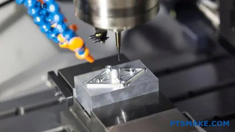
How are cutting tools for PEEK systematically classified?
Systematically classifying cutting tools is key for successful PEEK machining. It’s not just about picking any tool.
The classification boils down to two core factors. These are tool material and tool geometry.
Choosing correctly prevents common issues like melting or burring. At PTSMAKE, we always start here.
Tool Material Selection
The grade of PEEK dictates the tool material. Unfilled PEEK is different from fiber-reinforced grades.
| PEEK Grade | Recommended Tool Material | Reason |
|---|---|---|
| Unfilled PEEK | Uncoated Carbide | Cost-effective, sufficient hardness |
| Filled PEEK (Glass/Carbon) | Diamond-Coated (PCD) | Resists abrasive wear from fillers |
Tool Geometry Essentials
Proper geometry ensures a clean shearing action, not a plowing one. Sharpness is non-negotiable for a quality finish.
Understanding these classifications moves you from guesswork to precision. Let’s look deeper into why each element matters.
Breaking Down Tool Material Choices
For standard, unfilled PEEK, uncoated carbide is our go-to. It offers a great balance of performance and cost. It’s hard enough for the polymer without being overkill.
However, the game changes with filled grades. Carbon or glass fibers are extremely abrasive. They will quickly wear down a standard carbide tool. This leads to poor surface finish and dimensional inaccuracy.
For these abrasive grades, we rely on diamond-coated or Polycrystalline Diamond (PCD) tools. Their superior hardness and wear resistance are essential for maintaining a sharp edge and achieving tight tolerances throughout the production run.
The Critical Role of Tool Geometry
The right geometry reduces cutting forces and heat generation. This is vital for a thermally sensitive material like PEEK.
High Positive Rake Angles
A high positive rake angle10 helps "slice" the material cleanly. This shearing action minimizes deformation and heat, producing a better chip and surface finish.
High Relief Angles
High relief angles reduce friction. They prevent the tool flank from rubbing against the newly machined surface. This is crucial for avoiding thermal damage and melting.
Sharp Cutting Edges
A sharp edge is paramount. A honed or radiused edge, common for metals, will plow through PEEK. This generates excessive heat. A sharp, crisp edge ensures a clean cut with minimal burring.
In summary, classifying PEEK cutting tools by material and geometry is fundamental. The choice depends entirely on the PEEK grade. Uncoated carbide suits unfilled grades, while diamond-coated tools are essential for abrasive filled versions. Sharp, specific geometry is always required.
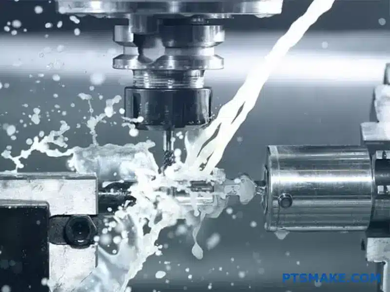
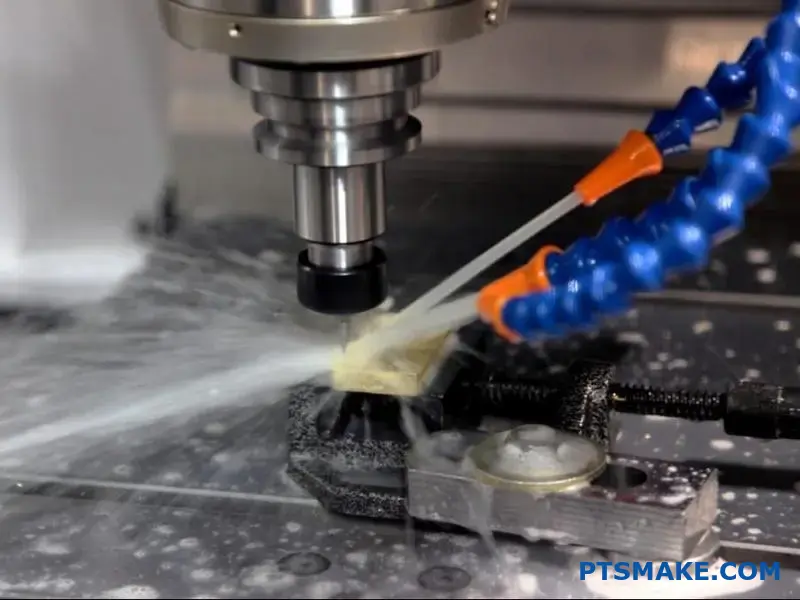
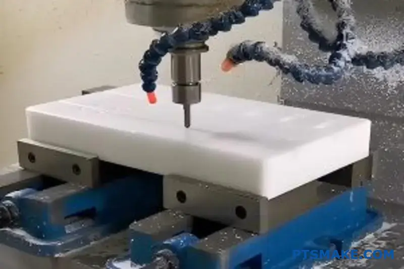
What are the different types of coolants for PEEK machining?
Choosing the right cooling method for PEEK is crucial. It directly impacts part quality and tool life. You don’t always need a liquid coolant.
The decision depends on the complexity of the part. Also, the cutting parameters play a big role. Let’s look at the main options available for your projects.
Cooling Strategies Overview
Here’s a quick comparison of the common methods. Each has its own place in PEEK machining.
| Method | Primary Function | Best For |
|---|---|---|
| Dry Machining | Chip Removal | Contamination-sensitive parts |
| Flood Coolant | Heat Removal | High-speed, heavy cuts |
| MQL | Lubrication & Cooling | Balanced performance |
Diving deeper, each method presents unique trade-offs. The optimal choice isn’t always obvious. It requires balancing thermal management, surface finish, and potential part contamination.
Dry Machining with Air Blast
We often start with dry machining for PEEK parts. PEEK doesn’t conduct heat well, so most heat goes into the chip. A strong air blast clears chips effectively. This prevents them from melting and sticking to the tool or part.
This method is perfect for medical or electronic components where coolant residue is unacceptable. However, for deep pockets or aggressive cuts, heat can build up, potentially accelerating tool wear.
Flood Coolant
For high-volume production or heavy material removal, a flood coolant is effective. We typically use standard water-soluble coolants. They are excellent at dissipating heat, allowing for faster machining speeds and extending tool life.
The main drawback is fluid absorption. PEEK can absorb a small amount of moisture, which might affect the dimensional stability of high-precision parts. Proper cleaning is also necessary post-machining.
Minimum Quantity Lubrication (MQL)
MQL is a smart middle ground. It sprays a tiny amount of oil in a high-pressure air stream. This provides just enough lubrication at the cutting edge to reduce friction. It also cools the tool and workpiece. MQL improves the tribological properties11 at the tool-chip interface without soaking the part.
It’s cleaner than flood cooling and offers better tool life than dry machining. The initial setup cost for MQL systems can be a consideration.
Selecting the right cooling strategy for PEEK machining involves a careful balance. You must consider part requirements, tool longevity, and cycle times. Each method—dry, flood, or MQL—offers distinct advantages and is suited for different application needs.
How do milling and turning PEEK present different challenges?
Milling and turning PEEK are fundamentally different. Each process presents unique challenges that we must manage carefully. Choosing the right one depends entirely on the part’s geometry.
Turning involves a continuous cut. This action generates significant heat very quickly. Without proper control, this heat can ruin the part.
Milling, on the other hand, uses interrupted cuts. The tool enters and exits the material, which helps with cooling. But, holding flexible PEEK parts steady for milling is a bigger challenge.
Here’s a quick comparison:
| Operation | Primary Challenge | Key Advantage |
|---|---|---|
| Turning | High Heat Buildup | Simple Workholding |
| Milling | Complex Fixturing | Better Heat Dissipation |
When machining PEEK, understanding the nuances between turning and milling is crucial for success. In past projects at PTSMAKE, we’ve seen how a small oversight in either process can lead to scrapped parts.
The Continuous Cut Challenge in Turning
In turning, the tool is always in contact with the PEEK workpiece. This continuous friction is the main source of heat. PEEK’s low thermal conductivity12 means it doesn’t transfer this heat away easily.
The heat gets trapped at the cutting point. This can cause the material to melt, gum up on the tool, or change its properties. We have found that precise control over speeds and feeds is essential.
Managing Heat in Turning
Sharp, coated tools are a must. They reduce friction. We also use high-pressure coolant directed precisely at the cutting zone. This actively pulls heat away, protecting both the tool and the part.
The Fixturing Puzzle in Milling
Milling’s interrupted cuts are great for cooling. However, the cutting forces can cause thin or flexible PEEK parts to vibrate or bend. If the part isn’t held securely, you lose all precision.
Our Approach to PEEK Fixturing
We often design custom fixtures for complex PEEK machining projects. Soft jaws or vacuum chucks can provide the necessary support without damaging the part’s surface. Proper fixturing is the foundation of precise PEEK milling.
| Challenge | Turning Solution | Milling Solution |
|---|---|---|
| Heat Control | High-Pressure Coolant | Interrupted Cuts |
| Part Stability | Simple Chucking | Custom Fixturing |
| Tool Wear | Sharp, Coated Inserts | Sharp, Coated End Mills |
Turning PEEK creates a high risk of heat buildup from its continuous cuts. Milling allows for better cooling due to interrupted cuts but makes fixturing flexible parts more complex. Both require specific strategies for a successful outcome.
What categories of defects are specific to PEEK parts?
When we machine PEEK, defects fall into clear groups. Understanding these helps us prevent them. It’s not just about what went wrong. It’s about why it happened.
For machinists, a practical view is best. We group issues by how they appear on the final part. This makes troubleshooting much faster.
Here’s how we categorize them at PTSMAKE:
| Category | Common Defects |
|---|---|
| Surface Quality | Tool marks, melting, discoloration |
| Edge Quality | Burrs, chipping, breakouts |
| Dimensional Accuracy | Warping, out-of-tolerance features |
This approach helps us target the root cause quickly.
A Closer Look at Defect Categories
Let’s break down these categories. Each one tells a different story about the PEEK machining process. Understanding them is key to achieving perfect parts.
Surface Quality Issues
Surface defects are immediately visible. They often relate to heat management and tool selection. Excessive heat can cause localized melting or smears. This ruins the finish.
Discoloration, usually a browning or darkening, is another sign of overheating. It indicates that the material’s properties might be compromised. The wrong cutting speed can also leave visible tool marks. These are unacceptable for high-precision applications.
Edge and Geometric Integrity
Edge quality is crucial, especially for parts with complex features. Burrs are thin ridges of material left on the edge. They are difficult to remove without damaging the part. Chipping occurs when material breaks away from the edge instead of cutting cleanly.
Dimensional and geometric defects are the most critical. Warping can happen due to internal stresses released during machining. Features can also be out-of-tolerance. This happens if the tool deflects or the part moves. This is often linked to the cutting forces and the fixture’s rigidity. Issues like Chatter13 can also severely impact the final dimensions.
| Defect Type | Primary Cause | PTSMAKE’s Proactive Solution |
|---|---|---|
| Melting/Smears | Excessive heat from friction | Optimize feeds, speeds, use sharp tools |
| Burrs/Chipping | Dull tools, incorrect tool path | Frequent tool inspection, specialized geometry |
| Warping | Internal material stress, heat | Proper material annealing, secure workholding |
Understanding these defect categories helps us refine our PEEK machining strategies. It ensures we deliver parts that meet the highest standards for our clients.
Categorizing PEEK defects into surface, edge, and dimensional issues allows for systematic troubleshooting. This structured approach helps machinists quickly identify and resolve problems, ensuring consistent quality and precision in every part produced.
How are post-machining annealing processes structured and categorized?
Annealing is not a one-size-fits-all process. We categorize it based on its specific purpose. The two main types serve very different functions in the machining workflow.
Stress-Relieving Annealing
This is an intermediate step. It occurs after rough machining to stabilize the part. This prevents warping before final, precise cuts are made.
Normalizing Annealing
This is a final finishing step. We perform it on the completed part. This optimizes its material properties and long-term performance.
| Annealing Type | Primary Goal | Timing in Workflow |
|---|---|---|
| Stress-Relieving | Stability & Dimensional Control | Mid-process |
| Normalizing | Maximize Performance | Post-machining |
This classification helps ensure the final component meets exact specifications.
Deeper Dive: Purpose-Driven Annealing
Understanding when to use each annealing type is crucial. At PTSMAKE, this decision directly impacts the final quality of every precision component we deliver.
Stress-Relieving for Stability
Heavy machining induces internal stresses in materials. This is especially true in complex PEEK Machining projects.
We use stress-relieving annealing after the rough cuts. The gentle heating relaxes the material’s molecular structure. This removes stress before it can cause distortion during the final finishing passes. This step is essential for parts with tight tolerances.
Normalizing for Peak Performance
Normalizing annealing is about unlocking a material’s full potential. We perform this on the final, fully machined part.
This process involves a controlled heating and cooling cycle. It aims to create a uniform and highly ordered microstructure. This maximizes properties like hardness and chemical resistance by increasing crystallinity14. Based on our project data, this step can significantly boost part lifespan.
| Feature | Stress-Relieving Annealing | Normalizing Annealing |
|---|---|---|
| Purpose | Remove internal stress | Optimize final properties |
| Timing | After rough machining | After all machining |
| Key Benefit | Prevents distortion | Enhances performance |
| Focus | Dimensional stability | Material structure |
Choosing the right process is a core part of our commitment. It ensures we deliver reliable, high-performance parts every time.
Post-machining annealing is categorized by function. Stress-relieving is a mid-process step for dimensional stability. Normalizing is a final treatment to maximize material strength and performance by refining its internal structure, ensuring reliability for the end-user.
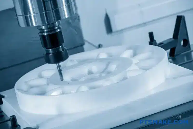
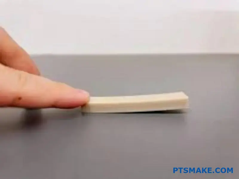
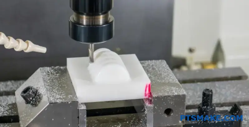
How to effectively machine thin-walled PEEK features without distortion?
Machining thin-walled PEEK is a true test of skill. The material can easily warp under pressure or heat. Preventing distortion isn’t about one single trick. It’s about a systematic, gentle approach.
In our projects at PTSMAKE, we rely on several key techniques. These methods help us maintain tight tolerances. They ensure the final part matches the design perfectly. Let’s explore these actionable strategies.

Machine in Stages
A common mistake is trying to remove too much material at once. For thin walls, this builds up stress and heat, causing warping. We always use a multi-stage process for PEEK machining.
First, we perform roughing passes. These remove the bulk of the material. But we intentionally leave a small amount of extra stock, typically around 0.2mm to 0.5mm.
Then, we let the part cool and stabilize. This allows internal stresses to relax. Finally, we execute light finishing passes to bring the part to its final dimensions.
Use Low Clamping Pressure
PEEK is a relatively soft material. Excessive clamping force will deform a thin-walled feature before you even start cutting. It’s crucial to hold the workpiece securely but gently.
We often design custom fixtures or use soft jaws. This distributes the clamping force evenly. It prevents marring the surface and avoids distortion. The key is just enough pressure to hold it, and no more. PEEK’s high Coefficient of Thermal Expansion15 also means that heat generated during machining can cause expansion, making clamping even trickier.
Employ Sharp Tools and Light Cuts
Dull tools don’t cut; they push and rub. This creates friction, heat, and high cutting forces. All of these are enemies of thin-walled PEEK features.
Using extremely sharp, new, or freshly ground cutting tools is non-negotiable. Combine this with light radial and axial depths of cut. This minimizes the force exerted on the part, reducing the chance of deflection.
| Technique | Benefit |
|---|---|
| Sharp Tools | Reduces cutting forces and heat. |
| Light Cuts | Minimizes material deflection. |
| High Spindle Speed | Allows for faster, cleaner shearing. |
| Appropriate Feed Rate | Prevents tool rubbing and melting. |
Utilize Climb Milling
For milling operations, the direction of the cut matters. We exclusively use climb milling for finishing thin walls.
In climb milling, the cutter rotates in the same direction as the feed. It cuts "down" into the material. This pulls the workpiece into the fixture and directs cutting forces downward. This greatly reduces the tendency for thin walls to deflect away from the cutter. Conventional milling, in contrast, pushes the material and can cause it to flex.
Mastering thin PEEK features requires a gentle touch. Use staged machining, low clamping pressure, sharp tools with light cuts, and climb milling. These steps are fundamental to preventing distortion and achieving the precise results your application demands.
How to prevent and remove burrs during the PEEK process?
Preventing burrs in PEEK machining is always the best strategy. It saves time and ensures part integrity. The key is using the right techniques from the start.
This involves exceptionally sharp cutting tools. It also means choosing the correct machining strategy.
For removal, delicate methods are necessary. Harsh abrasives can ruin the part’s surface. Let’s look at the best practices.
| Action Type | Recommended Method |
|---|---|
| Prevention | Exceptionally Sharp Tools |
| Prevention | Climb Milling |
| Correction | Manual Deburring (Sharp Tool) |
| Correction | Light Vapor Honing |
| Correction | Cryogenic Deburring |
Proactive Burr Prevention Strategies
At PTSMAKE, we emphasize prevention over correction. It is more efficient and maintains the highest quality for PEEK parts. Sharp tooling is non-negotiable. A sharp edge cleanly shears the material, minimizing the plastic deformation16 that leads to burrs. Dull tools push material, creating heavy burring.
We also prefer climb milling over conventional milling for PEEK. In climb milling, the cutter rotates with the direction of feed. This technique produces a thinner chip as the tooth exits the cut. This significantly reduces the likelihood of burr formation.
Effective Burr Removal Techniques
When burrs do occur, careful removal is crucial. Hand deburring with a very sharp tool can work for prototypes. However, it requires a steady, skilled hand.
For more consistent results, we turn to other methods.
| Method | Best Use Case | Key Consideration |
|---|---|---|
| Light Vapor Honing | Delicate parts, complex geometries | Gentle process, preserves surface finish |
| Cryogenic Deburring | High-volume production | Highly efficient, uses liquid nitrogen |
We strongly advise against using abrasive pads. They can embed particles into the PEEK surface. This contamination is unacceptable for medical and aerospace applications.
Preventing burrs in PEEK machining with sharp tools and climb milling is the ideal approach. When removal is needed, use precise methods like manual deburring, vapor honing, or cryogenic processes. Always avoid abrasive pads to prevent surface contamination.
What is the procedure for post-machining stress relief (annealing)?
The right annealing procedure is critical. It prevents part deformation later on. Think of it as a controlled relaxation for the material.
At PTSMAKE, we follow a precise recipe. This ensures stability and dimensional accuracy in every component we deliver. It’s a non-negotiable step.
Key Annealing Parameters
Here’s a simplified look at our process.
| Step | Action | Guideline |
|---|---|---|
| 1 | Heating | Slow ramp-up, approx. 50°F/hour. |
| 2 | Soaking | Hold at 300°F for 1 hour per inch of thickness. |
| 3 | Cooling | Slow ramp-down, matching the heating rate. |
This controlled cycle is essential for success.
A Step-by-Step Guide to Annealing
Let’s break down the process in more detail. Each step has a specific purpose that contributes to the final quality of the part. Getting this wrong can ruin an otherwise perfect component.
1. Preparation and Placement
First, we place the part in a programmable oven. It must have good air circulation. This ensures the part heats and cools evenly. Uneven temperatures create new stresses, defeating the purpose of annealing.
2. The Heating Cycle
We ramp up the temperature very slowly. A rate of about 50°F per hour is a good baseline. Rapid heating shocks the material. This slow increase allows the internal structure to adjust gradually without introducing new tension.
3. Soaking at Target Temperature
Once at the target temperature, like 300°F, we hold it. This "soaking" period is vital. The rule of thumb we follow is one hour for every inch of the material’s thickest section. This gives the stress enough time to fully dissipate throughout the material’s Crystalline structure17.
4. The Cooling Cycle
Cooling is just as important as heating. We ramp the temperature down slowly. Never quench the part by rapidly cooling it in water or air. Quenching locks in stress and can make the part brittle. This is especially true in PEEK machining, where material properties are paramount.
The success of post-machining stress relief hinges on a slow, controlled thermal cycle. Both heating and cooling rates are equally important. Rushing any step in the annealing process will compromise the part’s final stability and performance.
How to achieve a specific surface finish (Ra) on PEEK?
The final finishing pass is critical. It determines the final surface roughness (Ra) of your PEEK part. This is not the time for aggressive material removal. Instead, it’s about precision and control.
The Finishing Strategy
Your goal is a clean, shearing action. This approach minimizes stress on the material. It prevents melting or smearing, which are common issues in PEEK machining.
Here’s a quick guide to the parameters we use at PTSMAKE for the best results.
| Parameter | Recommendation |
|---|---|
| Tool | Dedicated finisher, large corner radius |
| Depth of Cut | Light (e.g., 0.005" – 0.010") |
| Cutting Speed | High |
| Feed Rate | Slow |
This combination consistently produces a superior finish.
Breaking Down the Finishing Parameters
Achieving a mirror-like finish on PEEK is a delicate balance. Each parameter plays a specific role. Let’s explore why this specific combination is so effective for high-quality PEEK machining.
Tool Selection: The Smoother
We always use a dedicated finishing tool. This tool should have a very sharp cutting edge. A large corner radius is essential. It acts like a wiper, smoothing out the peaks and valleys on the surface as it cuts. This action is what significantly lowers the Ra value.
The Cut: Light and Precise
A light depth of cut is non-negotiable. We recommend between 0.005" and 0.010". This minimal engagement reduces cutting forces. It minimizes heat generation and the risk of tool deflection18, ensuring the final dimensions are accurate.
Speed and Feed: A Controlled Dance
This is where the process becomes a careful dance.
| Factor | Effect on Finish |
|---|---|
| High Cutting Speed | Creates a clean shear, reducing burrs. |
| Slow Feed Rate | Minimizes tool marks for a smoother surface. |
Based on our tests with clients, this combination of high speed and slow feed allows each cutting edge to take a very small chip load. This prevents material from tearing and results in the best possible machined finish on PEEK components.
Achieving a superior PEEK surface finish relies on a dedicated finishing pass. The key is combining a large-radius tool with a light depth of cut, high cutting speed, and a slow feed rate for optimal, repeatable results.
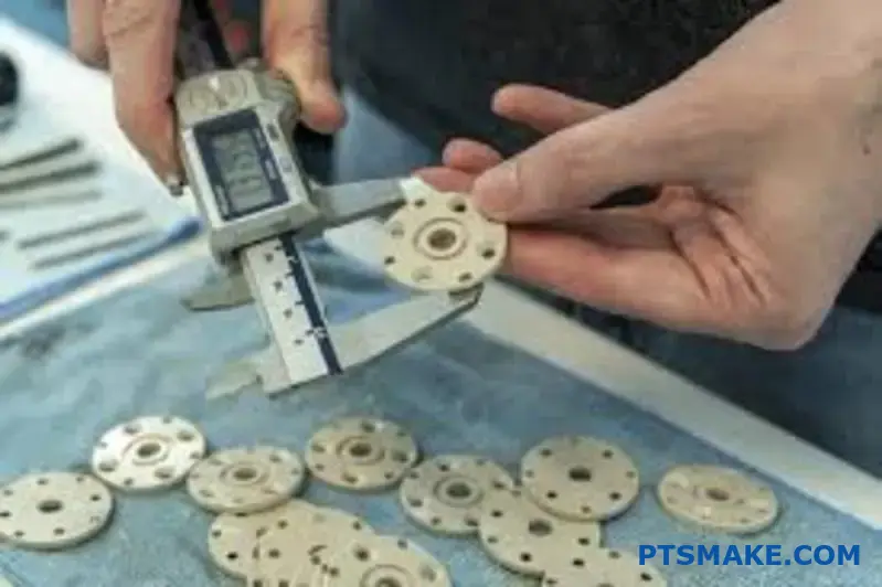
How to troubleshoot dimensional instability in finished PEEK components?
When a finished PEEK part changes size, it’s frustrating. The key is not to guess but to follow a clear diagnostic path. This structured approach saves time and material.
We can break the problem down into four key areas. Think of it as a checklist to find the root cause. This helps us work methodically.
Step 1: Check the Material
First, always verify the material’s history. Was the PEEK stock properly annealed? This step is critical for stabilizing the material before any PEEK Machining even begins.
Step 2: Review the Process
Next, look at your machining parameters. Aggressive cuts, especially during roughing, can introduce stress. This hidden stress can cause the part to warp later.
To dig deeper, a systematic workflow is your best tool. It removes assumptions and relies on evidence. Each step builds on the last, narrowing down the potential causes of dimensional change in your PEEK components.
Step 3: Inspect the Workholding
How the part was held is crucial. Over-tightening clamps can deform the raw material. This stress is released after machining, causing the part to move. The fixture must be secure but not induce stress.
Step 4: Measure Over Time
Measurement provides the final proof. An immediate check after machining gives you a baseline. But the real test is measuring again after 24 hours. This period allows internal stresses to relax.
This time-lapse measurement quantifies the instability. It shows you exactly how much the part is moving. This data is invaluable. It helps confirm if the issue is material stress or a machining parameter. We found that this method highlights even minor residual stress19 issues effectively.
Here is a simple log you can use:
| Measurement Point | Dimension A (mm) | Dimension B (mm) | Notes |
|---|---|---|---|
| Immediately After Machining | 100.05 | 50.02 | Fresh off the machine |
| 24 Hours Later | 99.98 | 50.01 | Part has settled |
This systematic approach isolates the variable causing instability.
A structured diagnostic workflow is essential. By methodically checking the material, process, workholding, and time-based measurements, you can efficiently identify and resolve the root cause of dimensional instability in PEEK parts, ensuring final component accuracy and reliability.
How to machine PEEK-GF30 (glass-filled) to minimize tool wear?
Machining PEEK-GF30 presents a unique challenge. The glass fibers that provide strength also make it extremely abrasive. This rapidly wears down standard cutting tools.
To combat this, an advanced strategy is essential. This involves using superior tooling, adjusting parameters, and managing the machining environment effectively. These steps are not optional for achieving consistent results.
The right approach protects your investment in tooling and ensures part quality.
| Tool Material | Wear Resistance | Recommended for PEEK-GF30 |
|---|---|---|
| Uncoated Carbide | Low | No |
| Coated Carbide | Medium | For short runs only |
| Diamond (PCD) | Extremely High | Yes, highly recommended |

The Unmatched Advantage of Diamond Tooling
When tackling PEEK-GF30, standard tools simply don’t last. The glass reinforcement acts like fine-grit sandpaper, quickly dulling the cutting edge. This is where advanced materials become necessary for any serious PEEK Machining operation.
Diamond-Coated Carbide and PCD
Polycrystalline Diamond (PCD) tools are the gold standard. Diamond is the hardest known material, making PCD tools exceptionally resistant to the material’s abrasive nature. Diamond-coated carbide tools offer a cost-effective alternative with significantly improved performance over standard carbide.
This choice directly impacts tool life and part consistency.
Mastering Cutting Parameters
You cannot machine PEEK-GF30 with the same settings as unfilled PEEK. The friction from the glass fibers generates substantial heat, which accelerates tool failure. The primary cause of this is the intense abrasive wear20 from the hard filler particles.
Reduce Cutting Speeds
Based on our tests with clients, reducing cutting speeds by 30-50% compared to unfilled PEEK is a good starting point. This lowers friction and heat at the cutting edge. It gives the tool a fighting chance against the relentless abrasion.
| Parameter | Guideline for PEEK-GF30 | Rationale |
|---|---|---|
| Speed (SFM) | Reduce 30-50% vs. Unfilled | Manages heat and friction |
| Feed (IPR) | Maintain or slightly reduce | Prevents tool chipping |
| Coolant | Flood coolant mandatory | Flushes abrasive particles |
The Power of Robust Flood Coolant
Coolant does more than just reduce heat. For PEEK-GF30, its most crucial role is to flush abrasive particles away from the cutting zone. Without effective chip evacuation, these glass fragments get caught between the tool and workpiece, acting as a grinding paste. A high-volume, high-pressure flood coolant system is non-negotiable for protecting the tool and the part finish.
To machine PEEK-GF30 effectively, a three-part strategy is key. Use ultra-hard tooling like PCD, reduce cutting speeds to manage heat and friction, and apply robust flood coolant to clear abrasive particles. This approach maximizes tool life and ensures part integrity.
How would you quote a complex PEEK machining job accurately?
Integrating technical knowledge into business practice is key. An accurate quote for complex PEEK machining goes beyond simple calculations. It requires a deep understanding of the material’s unique properties.
You must factor in higher material costs. PEEK is significantly more expensive than aluminum. Cycle times are also slower to manage heat and avoid stress.
Key Quoting Adjustments
| Factor | PEEK vs. Aluminum | Impact on Quote |
|---|---|---|
| Material Cost | Much Higher | Increases base cost significantly |
| Cycle Time | Slower | Adds to machine time & labor |
| Tooling | Specialized (PCD) | Higher initial tool cost |
These elements must be clearly accounted for in your business practice.
Deeper Dive into Hidden Costs
Quoting a PEEK machining job accurately means looking at the subtle details. It’s not just about the raw material cost. You must consider how PEEK behaves during and after machining.
For example, filled grades of PEEK containing glass or carbon fiber are highly abrasive. Standard cutting tools wear out quickly. This forces the use of Polycrystalline Diamond (PCD) tooling, which has a higher upfront cost but is necessary for maintaining tolerances.
Post-Machining Considerations
The work isn’t over when the machine stops. Careful handling and deburring are critical. PEEK is a tough material, and burrs require meticulous manual removal, adding significant labor time.
Furthermore, for high-precision parts, an annealing cycle is often required. This process relieves internal stresses built up during machining. It prevents warping and ensures dimensional stability. Controlling the material’s crystallinity21 is vital for performance.
These post-processing steps are not optional for complex jobs. At PTSMAKE, we factor them into our quotes to prevent surprises.
| Process | Reason | Impact on Quote |
|---|---|---|
| PCD Tooling | For abrasive filled grades | Higher tooling budget |
| Careful Deburring | Avoids part damage | Increased skilled labor time |
| Annealing | Relieves stress, ensures stability | Adds process time & cost |
Accurate PEEK machining quotes must integrate these technical realities. Factoring in higher material cost, specialized tooling for filled grades, and essential post-processing like annealing and deburring ensures a realistic and trustworthy price for your client.
Unlock Advanced PEEK Machining with PTSMAKE Expertise
Ready to elevate your next PEEK machining project? Contact PTSMAKE for a precise quote and discover how our specialized knowledge, state-of-the-art technology, and dedicated service deliver reliable, high-tolerance PEEK components—on time and to your exact specifications. Start your inquiry with PTSMAKE today!

Discover how this critical temperature impacts material behavior and machining strategies. ↩
Learn the science behind residual stress and its impact on polymer performance. ↩
Understand how fiber direction impacts material strength and performance. ↩
Understand how temperature critically affects PEEK’s structural integrity and machining behavior. ↩
Understand the mechanics of material failure and how it impacts final part quality. ↩
Discover the science behind this failure mode and how to prevent it in composite materials. ↩
Learn how this critical property affects material behavior during machining and other thermal processes. ↩
Understand how changes in molecular structure affect the final part’s mechanical properties and performance. ↩
Learn how material properties affect suitability for medical device applications. ↩
Click to see how this crucial angle impacts cutting forces, chip control, and final part quality. ↩
Learn how friction, wear, and lubrication principles can impact your machining outcomes. ↩
Learn how a material’s ability to transfer heat impacts your PEEK machining project. ↩
Understand the causes of this vibration and how to eliminate it for a flawless surface finish. ↩
Discover how a material’s internal structure affects its real-world durability and strength. ↩
Learn how this material property influences design and machining strategies. ↩
Understand how material behavior impacts machining quality to prevent defects like burrs. ↩
Click to understand how a material’s internal structure affects its stability and machining results. ↩
Learn how tool deflection can impact the precision and surface quality of your machined parts. ↩
Learn more about how internal stresses affect material stability and part accuracy. ↩
Learn how material fillers contribute to the rapid degradation of cutting tools. ↩
Understand how PEEK’s internal structure impacts stability and machining, which is vital for precision components. ↩