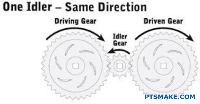
Many engineers treat idler gears as simple rotating components that just reverse direction. This oversimplified view leads to costly design mistakes, unexpected failures, and missed opportunities for system optimization.
An idler gear is a transmission component that modifies torque direction, adjusts spatial packaging, and influences system dynamics including inertia, stiffness, and vibration characteristics beyond basic rotation reversal.
I’ve worked with engineering teams who discovered too late that their idler design created resonance issues or premature bearing failures. This guide covers the advanced principles I use at PTSMAKE to help clients design robust idler systems for applications ranging from precision robotics to heavy machinery.
What defines an idler gear beyond merely reversing rotation?
Most engineers see an idler gear and think one thing: reversing rotation. While true, that’s only the beginning of the story. Its role is far more strategic.
An idler gear is a key component for managing system dynamics and spatial constraints. It is not just a passive placeholder in a gear train.
The Basic vs. Advanced View
| Function | Basic Understanding | Advanced Application |
|---|---|---|
| Rotation | Reverses direction | No change in gear ratio |
| Purpose | Simple directional change | Manages system dynamics |
This gear can fundamentally alter a machine’s performance. It goes well beyond its simple, textbook definition.
Thinking from first principles reveals its true value. An idler is not just a link; it’s a dynamic tuning element within a powertrain. Its placement and properties are critical.
Impact on System Dynamics
An idler gear introduces its own mass and elasticity. This directly influences the entire system’s mechanical behavior.
Modifying Inertia and Stiffness
Adding an idler increases the total rotational inertia of the system. This can help smooth out torque fluctuations. It also affects the overall torsional stiffness. This influences how the system responds to load changes.
Spatial and Transmission Considerations
In complex machinery, space is a premium. An idler gear allows engineers to bridge distances between shafts. This provides essential packaging flexibility. It also allows designers to avoid obstacles within the machine’s architecture.
However, an idler introduces additional mesh points. Each mesh can contribute to the system’s overall transmission error1. Careful design is crucial. In our experience at PTSMAKE, a precision-machined idler minimizes this effect, preserving system accuracy.
| System Property | Effect of Adding an Idler Gear | Design Consideration |
|---|---|---|
| System Inertia | Increases | Can stabilize or slow response |
| Torsional Stiffness | Changes | Impacts vibration and deflection |
| Spatial Layout | Increases flexibility | Critical for compact designs |
| Transmission Error | Adds potential source | Requires high-precision manufacturing |
An idler gear is a crucial design tool, not just a simple direction reverser. It actively modifies system inertia, stiffness, and packaging, requiring careful engineering consideration to balance its benefits against potential drawbacks like increased transmission error.
What is the information-theoretic role of an idler in a transmission?
An idler gear is not just a mechanical spacer. It acts as a crucial channel for transmitting information. This information is kinematic—it relates to motion. Think of it as passing a message.
The Perfect Information Relay
Ideally, an idler gear transmits this kinematic data without any loss. The output gear’s motion perfectly mirrors the input gear’s motion, just with a reversed direction.
Real-World Information Noise
However, no component is perfect. Tiny imperfections in an idler gear introduce "noise" or errors. This noise corrupts the kinematic information being transmitted.
| Information Type | Ideal Transmission | Real-World Corruption |
|---|---|---|
| Position | Exact angular transfer | Small positional errors |
| Velocity | Constant, smooth transfer | Fluctuations in speed |
| Timing | Precise synchronization | Timing inaccuracies (jitter) |
This can affect the performance of a whole system.
Decoding Kinematic Information Transfer
At its core, a gear train is an information processing system. The input gear encodes information about position and velocity. Each subsequent gear, including any idler, relays this message.
The role of an idler gear is to ensure this information reaches its destination intact. But what happens when the messenger isn’t perfect?
Sources of Informational Noise
Every manufacturing imperfection introduces a potential error. These errors accumulate through the system. For instance, even slight tooth profile deviations can cause velocity fluctuations.
This is why precision is non-negotiable. At PTSMAKE, we focus on minimizing these imperfections. We control factors like concentricity and surface finish. This ensures the kinematic message is as clear as possible.
A common issue is the small gap between meshing gear teeth. This gap, known as backlash2, can cause a delay in the information transfer when the direction of rotation changes. It introduces uncertainty in the output position.
Below are common sources of error we manage.
| Imperfection Source | Type of "Noise" Introduced | Consequence |
|---|---|---|
| Tooth Profile Error | Velocity Fluctuation | Uneven motion, vibration |
| Gear Eccentricity | Positional Error | Inconsistent timing, wear |
| Surface Finish | Frictional Loss | Reduced efficiency, heat |
| Material Defects | Premature Wear | System failure, data loss |
Through meticulous CNC machining and quality control, we fight against this informational decay. Our goal is to make each component a high-fidelity transmitter.
An idler gear is a channel for kinematic information. Its physical quality directly impacts the quality of the transmitted data. Imperfections introduce noise, leading to errors in position, velocity, and timing. Minimizing these flaws through precision manufacturing is essential for system reliability.
What is a robust taxonomy for idlers based on dynamic function?
A component’s shape only tells half the story. To truly understand an idler gear, we must look at its job. Classifying idlers by dynamic function moves us beyond simple geometry.
This approach focuses on what the idler does. Is it maintaining tension? Is it absorbing shock? Or is it guiding precise, rapid movements?
This functional perspective is key. It directly influences material selection, bearing choice, and overall system integration. A simple table below outlines these core functions.
| Functional Category | Primary Role | Key Design Driver |
|---|---|---|
| Tensioning | Maintain consistent tension | Durability & load capacity |
| Damping | Absorb vibration and noise | Material properties |
| Transmission | Guide high-speed motion | Precision & low inertia |
A Deeper Dive into Functional Roles
Let’s break down these functional categories further. Each role demands a different engineering approach, something we constantly navigate in projects at PTSMAKE. Understanding this is crucial for successful design.
Tensioning Idlers
These are the workhorses. Their main job is to apply a constant force on a belt or chain. This prevents slippage and ensures consistent power transmission. The design must focus on robust bearings and materials that resist wear under constant load.
Vibration Damping Idlers
In many systems, noise and vibration are major problems. Damping idlers are designed to absorb this unwanted energy. Their effectiveness is highly dependent on material science. The use of specific polymers allows for significant viscoelastic damping3. This converts mechanical shock into negligible heat, quieting the system.
High-Frequency Motion Transmission Idlers
Think of robotics or high-speed printers. Here, idlers guide belts with extreme precision and speed. The priority is low inertia and perfect balance. These parts are often CNC machined from lightweight aluminum to minimize rotational mass and ensure accuracy.
| Idler Type | Common Material | Key Characteristic | Typical Application |
|---|---|---|---|
| Tensioning | Steel, Hard Polymers | High Wear Resistance | Conveyor Systems |
| Damping | Elastomers, Sorbothane | High Hysteresis | Automotive Engines |
| Transmission | Aluminum, Acetal | Low Inertia, Balance | 3D Printers, Robotics |
Categorizing idlers by dynamic function provides a powerful framework. This approach moves beyond simple shape and forces a focus on performance requirements, leading to better material choices, improved system reliability, and longer component life.
How do idler configurations differ in precision robotics vs. heavy machinery?
The structural design of an idler gear is fundamentally different. It all depends on its final application.
Precision robotics requires gears for low-backlash and high-stiffness. Heavy machinery needs them for high-torque and shock-load environments.
Key Design Drivers
A gear’s purpose dictates its form. For robotics, accuracy is everything. For heavy equipment, it’s about pure strength and endurance.
| Feature | Precision Robotics | Heavy Machinery |
|---|---|---|
| Primary Goal | Positional Accuracy | Durability & Power |
| Backlash | Near-Zero | Tolerable |
| Stiffness | Very High | Moderate |
These opposing needs lead to very different structural classifications.
Contrasting Structural Classifications
Let’s break down the design philosophies. Precision robotics idlers often use fine-pitch teeth. This maximizes contact and minimizes movement slop. They might also feature anti-backlash mechanisms, like split gears loaded with springs.
Heavy machinery idlers are the opposite. They use coarse-pitch, robust teeth. This design is less about precision and more about surviving immense force.
Material and Profile Choices
The material choice is critical. In robotics, we often use lightweight alloys or hardened steel. Sometimes, high-grade polymers are used for their low inertia. The tooth profile is optimized for smooth, continuous engagement.
In heavy machinery, you’ll find tough, forged steels. These are designed to withstand sudden impacts. The Hertzian contact stress4 calculations are paramount here. This ensures the gear teeth don’t deform or fracture under extreme, sudden loads. The focus is on strength, not finesse.
| Aspect | Low-Backlash (Robotics) | High-Torque (Heavy Machinery) |
|---|---|---|
| Tooth Pitch | Fine | Coarse |
| Materials | Hardened Steel, Alloys, Polymers | Forged Steel, Cast Iron |
| Key Feature | Anti-Backlash Designs | High Shock Resistance |
| Manufacturing | High-Precision Grinding | Hobbing, Forging |
At PTSMAKE, we understand these nuances. We leverage our advanced CNC machining to produce high-precision idler gears. This is essential for the demanding needs of the robotics industry.
The structural design of an idler gear reflects its intended use. Robotics applications demand fine features for accuracy. Heavy machinery requires robust, durable structures to handle high torque and severe shock loads, prioritizing strength over precision.
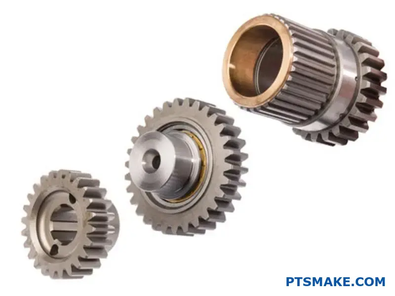
Bearing Choice Defines the System: A Head-to-Head Comparison
Your choice of bearing is a fundamental design decision. It is not just a component swap. It dictates the entire system’s character.
This selection defines load capacity, speed limits, and even how the system fails. Journal and roller bearings create two distinct classes of idler systems.
Let’s break down the key differences.
| Feature | Journal Bearing System | Roller Bearing System |
|---|---|---|
| Primary Motion | Sliding | Rolling |
| Load Capacity | Moderate | High to Very High |
| Friction Level | Higher (Sliding) | Lower (Rolling) |
| Speed Limit | Lower | Higher |
Load Capacity and Frictional Loss
Roller bearings handle heavier loads. Their design spreads force across lines or points. This gives them a huge advantage for demanding jobs.
Journal bearings distribute load over a surface. This is effective for many uses but has clear limitations under high stress.
Friction is another major difference. In past projects at PTSMAKE, we’ve seen roller bearings significantly cut energy use. They roll, while journals slide. This directly impacts overall system efficiency and heat generation. An efficient Idler Gear system often relies on this principle.
Speed Limits and Failure Modes
Speed is often limited by heat. The sliding friction in journal bearings generates more heat. This caps their operational speed.
Roller bearings run cooler, allowing for much higher RPMs. This makes them the go-to choice for high-speed machinery applications.
Failure characteristics are also very different. A journal bearing typically wears down gradually. You often get an audible or visible warning.
A roller bearing, however, can fail suddenly. This can happen through a process like spalling5. This failure can be catastrophic with little warning. Understanding this is key for maintenance planning and system safety.
Your bearing selection fundamentally defines the idler system. It’s a trade-off between load, speed, efficiency, and failure predictability. This choice directly impacts performance, reliability, and lifetime cost, making it a critical engineering decision from the start.
What are the structural differences in planetary versus fixed-axis idlers?
Planetary and fixed-axis idlers serve similar purposes. However, their structural designs are fundamentally different. This impacts how they handle loads and perform kinematically.
Design Philosophy
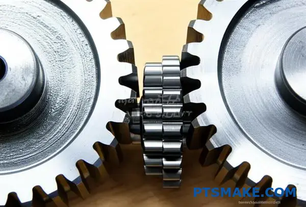
A fixed-axis idler gear is simple. It sits on a stationary shaft. In contrast, planetary gears orbit a central sun gear. They are part of a more complex carrier assembly.
Core Functional Differences
Let’s break down the key distinctions.
| Feature | Fixed-Axis Idler | Planetary Idler (Planet Gear) |
|---|---|---|
| Axis of Rotation | Fixed, stationary | Rotates around its own axis and orbits a central axis |
| Complexity | Low | High |
| Load Distribution | Concentrated | Distributed among multiple gears |
This structural contrast leads to very different performance outcomes in a transmission.
Diving deeper, the differences become even more significant. Fixed-axis idlers are straightforward. They mount on a non-moving pin or shaft. Their simplicity makes them robust and cost-effective for basic transmission tasks.
Load Handling and Stress
The most critical difference is load distribution. A single fixed-axis idler gear bears the entire load transferred between the driving and driven gears. This concentrates stress on its teeth and bearings.
Planetary systems, however, share the load. Multiple planet gears distribute torque evenly around the central sun gear. This dramatically reduces stress on individual components. It allows for higher torque capacity in a smaller package, a key benefit we focus on at PTSMAKE.
Kinematic Function Explained
Kinematically, a fixed-axis idler’s job is simple. It just reverses the direction of rotation.
Planetary gears exhibit a more complex epicyclic motion6. They rotate on their own axes while also orbiting the sun gear. This dual motion enables high gear reductions or increases within a very compact space.
| Aspect | Fixed-Axis Idler | Planetary Idler |
|---|---|---|
| Torque Capacity | Lower (for a given size) | Higher |
| Gear Ratio | N/A (reverses direction) | High reduction/overdrive possible |
| Application | Simple power transmission | Automotive transmissions, robotics |
| Precision Needs | Standard | Very high tolerances required |
This complexity is why precision manufacturing is so vital for planetary gear sets.
In short, planetary idlers provide a compact, high-torque solution by distributing loads and offering complex motion. Fixed-axis idlers are simpler, providing direct power transfer and rotation reversal with concentrated loading. Each has its place in mechanical design.
What is the methodology for designing an idler for minimal NVH?
Designing an idler for minimal NVH is a systematic process. It’s not about one single trick. It’s a holistic approach.
We focus on three core areas. These are tooth micro-geometry, material choice, and housing design. Each plays a critical role.
Getting these right ensures a quiet and smooth operation. This is crucial for high-performance applications.
Systematic Design Pillars
| Design Pillar | Primary Goal | Key Action |
|---|---|---|
| Micro-Geometry | Reduce transmission error | Profile & lead correction |
| Material Selection | Dampen vibrations | Choose high-damping materials |
| Housing Design | Avoid resonance | Increase stiffness & isolation |
This structured method prevents costly downstream fixes. It builds quality in from the start.
Designing a quiet Idler Gear requires deep engineering focus. It goes far beyond standard gear calculations. We must fine-tune the smallest details to control noise and vibration at the source.
Deep Dive into Micro-Geometry
The gear tooth shape is the first line of defense against noise. Even tiny deviations can cause significant whining or rattling sounds.
Profile and Lead Correction
We modify the tooth profile to compensate for deflection under load. This ensures smooth contact as gears mesh. It prevents sharp impacts that generate noise. Proper correction minimizes the transmission error7, which is a primary source of gear noise.
Lead correction addresses alignment issues along the tooth face. This ensures the load is distributed evenly, further reducing vibration.
Material Selection and Housing Integration
The material of the Idler Gear and its housing are equally important. They determine how vibrations are absorbed or amplified.
In our work at PTSMAKE, we often suggest advanced polymers for their excellent damping properties. However, material choice always depends on load and temperature requirements.
| Material | Damping Capacity | Strength | Cost Factor |
|---|---|---|---|
| Steel | Low | High | Medium |
| Cast Iron | Medium | Medium | Low |
| PEEK | High | Medium-High | High |
| Nylon (PA) | Very High | Low-Medium | Low |
A stiff housing is also essential. A flexible housing can resonate with gear mesh frequencies, creating a lot of noise. We design housings to shift these resonant frequencies away from the operating range.
A successful low-NVH design integrates micro-geometry, material science, and structural dynamics. It’s a comprehensive approach that considers how the idler gear interacts with the entire system for optimal performance.
How to perform a multi-objective optimization for an idler gear?
Setting up the optimization problem correctly is the most crucial step. A clear plan prevents costly rework later. It all starts with defining what you want to achieve.
We must clearly identify our goals. Are we aiming for a lighter part? Or a longer-lasting one? These are often competing objectives.
Defining Your Goals
First, we define what success looks like. This involves selecting objective functions. These are the metrics you want to maximize or minimize.
Key Objectives
A common starting point is a simple table. It helps clarify the main goals for your idler gear.
| Objective | Goal | Common Metric |
|---|---|---|
| Mass | Minimize | Grams (g) |
| Service Life | Maximize | Rotational Cycles |
| Efficiency | Maximize | Power Loss (%) |
| Manufacturing Cost | Minimize | Cost per unit |
This framework helps you focus on what truly matters for your application.
With our goals defined, we can dive deeper. This means understanding the trade-offs and the limits of our design. It’s not just about what we want. It’s also about what is possible.
Identifying Design Variables and Constraints
The first step is identifying the key design variables8 that we can actually control. These are the geometric or material properties we can change. For an idler gear, this could be the module, face width, or material choice.
Next, we establish constraints. These are the non-negotiable limits your design must respect. Think of them as the rules of the game. They ensure the final design is practical and safe.
In our work at PTSMAKE, we help clients distinguish between "wants" and "needs." This is the core of setting up a successful optimization problem.
Common Constraints
Here is a breakdown of typical constraints you might encounter.
| Constraint Category | Example | Reason |
|---|---|---|
| Geometric | Maximum outer diameter | Must fit within an existing assembly or housing. |
| Material Strength | Bending stress limit (MPa) | To prevent tooth failure under load. |
| Performance | Minimum contact ratio | To ensure smooth, continuous power transmission. |
| Manufacturing | Minimum tooth thickness | Limited by the CNC tool or molding process. |
Defining these boundaries prevents the optimization from producing impossible designs. It focuses the effort on realistic, manufacturable solutions.
Defining the objectives, variables, and constraints is the foundation of any successful idler gear optimization. This structured approach ensures all engineering requirements are met while pushing for the best possible performance within the given boundaries.
Analyze a catastrophic idler failure in a high-performance racing engine.
Let’s examine a real-world failure. A GT-class race car suffered a sudden engine breakdown mid-race. The initial telemetry pointed to a timing system issue. The teardown quickly revealed the cause: a shattered idler gear.
This wasn’t just a simple component break. It was a catastrophic event that destroyed the valvetrain. Our task was to find the root cause. Was it a faulty part? Or a larger system issue? Understanding why is key.
Here is a quick overview of the initial findings:
| Component | Status | Initial Notes |
|---|---|---|
| Idler Gear | Shattered | Multiple fracture points |
| Timing Belt | Snapped | Torn near the idler |
| Valves | Bent | Piston collision confirmed |
| Pistons | Damaged | Impact marks from valves |
Deep Dive into the Failure Analysis
A visual inspection wasn’t enough. We needed a systematic approach. At PTSMAKE, we apply similar diagnostic principles to prevent failures in the parts we manufacture. A component failure is rarely due to a single cause.
Initial Metallurgical Review
We started with the gear fragments. Under a microscope, we found evidence of fatigue cracking. The cracks originated at the root of a gear tooth. This suggested a stress concentration point. But it didn’t explain the ultimate, catastrophic failure. The material composition was within specification.
Investigating System Dynamics
High-performance engines produce intense vibrations. The engine’s timing system must handle these forces. We analyzed the engine’s operational data just before the failure. The data showed unusual harmonic frequencies.
This pointed towards excessive torsional vibration9 in the crankshaft. This vibration, not accounted for in the original design, likely overloaded the idler gear over many cycles. The gear was strong, but not for this unexpected stress.
Root Cause Determination
The final verdict combined two factors. A minor stress riser at the tooth root was the initiation point. However, the unexpected system vibration was the driving force. It accelerated the fatigue process, leading to a rapid and complete failure.
| Potential Cause | Evidence | Conclusion |
|---|---|---|
| Material Defect | Negative | Material met all specs |
| Manufacturing Error | Minor | Small stress riser found |
| System Overload | Positive | Telemetry shows high vibration |
| Maintenance Issue | Negative | Component was within service life |
In summary, the failure was not a simple part defect. It resulted from a system-level dynamic overload that exploited a minor manufacturing imperfection in the idler gear. This highlights the need to analyze the entire operational environment.
How to integrate smart sensors within an idler gear assembly?
Let’s discuss the ‘smart idler’ concept. It’s not just a component; it’s a proactive health monitor for your machinery.
By embedding sensors, a standard idler gear transforms. It becomes a source of vital, real-time data. This moves maintenance from reactive to predictive. It helps prevent failures before they happen, saving time and money.
Key Integrated Sensors
We focus on three main sensor types. Each tracks a different part of the gear’s health. This gives a complete operational view.
| Sensor Type | Function | Monitored Parameter |
|---|---|---|
| Strain Gauge | Measures stress | Mechanical Load |
| Thermocouple | Tracks heat | Operating Temperature |
| Accelerometer | Detects shaking | Vibration Levels |
This data provides a full picture of performance.
Designing the Smart Idler Gear
Creating a ‘smart idler’ is a precision challenge. The placement of sensors is crucial. We must embed them without weakening the gear’s structural integrity. This requires careful design and expert machining capabilities. In past projects at PTSMAKE, we have successfully met this balance.
Data for Predictive Maintenance
These embedded sensors collect vital operational data. This information is then sent for analysis. For example, rising temperatures can indicate lubrication failure. Increased vibration often points to bearing wear. This is where telemetry10 plays a key role in effective remote monitoring.
The Data-to-Action Pathway
The real value comes from turning data into action. The system can send alerts to maintenance teams. This allows for planned repairs, avoiding sudden breakdowns. Our test results show this can greatly increase machine uptime and overall productivity.
| Data Point | Potential Issue | Maintenance Action |
|---|---|---|
| High Temperature | Lubrication Failure | Schedule Lubrication |
| Vibration Spike | Bearing Wear | Inspect/Replace Bearing |
| Abnormal Strain | Overload Condition | Adjust Load/Operation |
This smart system makes maintenance efficient. It turns a simple idler gear into a guardian of your machine’s health.
The ‘smart idler’ concept uses embedded sensors for real-time data. This turns a mechanical part into a data hub, enabling predictive maintenance. It boosts reliability and cuts unplanned downtime by spotting issues before they cause failure.
What is the future role of idlers in EV transmissions?
Electric vehicles operate differently than traditional cars. Their motors are nearly silent and spin at incredibly high speeds.
This creates unique challenges for transmission components like the idler gear. Any noise from the gearbox becomes much more noticeable.
The NVH Challenge
Noise, Vibration, and Harshness (NVH) is a major focus. The quiet EV environment means gear whine, previously masked by engine noise, is now a primary concern for driver comfort.
High-Speed Demands
EV motors can exceed 20,000 RPM. This puts immense stress on gears, demanding innovation in design, materials, and overall function to ensure durability and efficiency.
| Challenge | Impact on Idler Gear |
|---|---|
| Low Noise (NVH) | Requires precision tooth profiles and damping materials. |
| High Speed (RPM) | Demands lightweight, high-strength materials and low inertia. |
| High Efficiency | Needs low-friction surfaces and optimized geometry. |
The specific needs of EV powertrains are pushing idler gear technology forward. We’re moving beyond simple steel gears into a new era of specialized components. Innovation is focused on three key areas.
Advancements in Gear Design
To combat noise, engineers are developing new gear tooth geometries. This includes things like asymmetric profiles and higher contact ratios, which smooth the transfer of power and reduce whine.
Precision is everything here. At PTSMAKE, our CNC machining capabilities allow us to create these complex profiles with the tight tolerances required for quiet operation.
The Shift in Materials
Material science is playing a huge role. Instead of just steel, we’re seeing high-performance polymers, composites, and specialized metal alloys. These materials reduce weight and inertia, which is crucial for high-speed performance.
Applying advanced tribological coatings11 is also becoming standard practice. These ultra-thin layers dramatically reduce friction and wear, extending the life of the transmission and improving overall efficiency.
Evolving Idler Function
The idler gear of the future might do more than just transfer power. We are exploring concepts where idlers integrate sensors. These could monitor torque, temperature, or vibration in real-time. This data can help optimize performance and predict maintenance needs.
| Innovation Area | Key Driver | Desired Outcome |
|---|---|---|
| Design | Low NVH | Quieter Operation, Smoother Ride |
| Materials | High RPM & Efficiency | Lower Inertia, Reduced Wear |
| Function | System Optimization | Predictive Maintenance, Better Control |
EV requirements for quiet, high-speed operation are fundamentally changing the idler gear. Innovation is focused on advanced designs to reduce noise, new materials for durability, and expanded functionality that integrates the gear more deeply into the vehicle’s systems.
How could additive manufacturing revolutionize complex idler gear design?
Additive manufacturing unlocks new design frontiers. It looks beyond a part’s external shape. We can now engineer the component’s internal structure.
Optimizing From The Inside Out
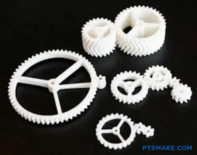
This means creating complex internal geometries. These are impossible with traditional methods like machining. We can design an idler gear for very specific functions.
This approach transforms performance. It focuses on making parts lighter and more efficient.
Internal Feature Possibilities
| Feature | Traditional Manufacturing | Additive Manufacturing |
|---|---|---|
| Internal Structure | Solid or simply hollowed | Optimized internal lattice |
| Cooling System | External or passive | Integrated cooling channels |
| Material Properties | Homogeneous (uniform) | Functionally graded |
This shift gives engineers true design freedom.
Unlocking Advanced Geometries
Additive manufacturing builds parts layer by layer. This process gives us precise control. We can introduce incredible internal complexity. This fundamentally changes the potential for idler gear design.
Lightweighting with Lattice Structures
We can replace solid material with internal lattices. These structures are strong yet lightweight. This design reduces weight and inertia significantly. In past projects at PTSMAKE, we have cut part weight by over 40% without losing strength.
Integrated Cooling Channels
High-speed idler gear applications generate intense heat. This can lead to premature failure. With 3D printing, we can embed cooling channels directly into the gear. These channels can follow complex paths, removing heat where it matters most.
Tailored Material Properties
We can also use Functionally Graded Materials12. This technique lets us vary material composition across a single part. Imagine an idler gear with a hard, wear-resistant tooth surface and a tougher, more ductile core.
| AM Feature | Primary Benefit | Ideal Application |
|---|---|---|
| Internal Lattices | Weight & Inertia Reduction | Aerospace, High-Performance Robotics |
| Cooling Channels | Enhanced Thermal Management | High-Speed Automotive Transmissions |
| FGM | Customized Performance | Heavy-Duty Industrial Machinery |
This level of part-specific optimization was previously out of reach.
Additive manufacturing truly transforms the idler gear from within. By integrating features like lattice structures and cooling channels, we create parts that are lighter and more efficient, pushing performance far beyond the limits of traditional manufacturing.
Propose a novel idler design for a deep-space robotic application.
Designing for deep space presents unique challenges. An idler gear must endure extreme temperatures. It also needs to function flawlessly in a vacuum.
On Earth, we can perform maintenance. In space, that is not an option. This requires absolute reliability from every single component.
Our design focuses on solving these core issues. We use novel materials and advanced engineering.
Here is how space conditions differ from terrestrial ones:
| Feature | Terrestrial Environment | Deep-Space Environment |
|---|---|---|
| Temperature | -20°C to 40°C | -150°C to 120°C |
| Atmosphere | Standard Pressure | Near-Vacuum |
| Maintenance | Regular Access | Impossible |
Material Selection for the Void
Standard metals and plastics won’t work. Many steels become brittle in extreme cold. Polymers can be destroyed by radiation. You need something special for your idler gear.
We propose a custom-formulated PEEK (polyetheretherketone) composite. This material is infused with specific additives. It provides excellent mechanical strength and radiation resistance.
Overcoming the Lubrication Hurdle
In a vacuum, wet lubricants are useless. They either freeze solid or boil away into space. This process, related to a material’s outgassing13 properties, can harm sensitive equipment like cameras and sensors. This makes lubrication a major design challenge.
Our solution is a solid lubricant. We use a proprietary tungsten disulfide (WS2) coating. This dry film provides an extremely low-friction surface. It remains stable across the vast temperature swings found in space. This is critical for a maintenance-free system.
A New Approach to Gear Geometry
Thermal expansion and contraction are significant. A standard gear profile would bind or become loose. Our design uses a special tooth profile.
Based on our test results, this profile maintains perfect meshing. This ensures smooth operation regardless of temperature. At PTSMAKE, our precision CNC machining capabilities are vital to creating these complex, high-tolerance components.
Our proposed idler gear design uses a PEEK composite and a solid WS2 lubricant. This approach solves the core problems of extreme temperatures and vacuum, ensuring long-term, maintenance-free reliability for deep-space applications.
How to use an idler to solve a complex packaging constraint problem?
In a recent project at PTSMAKE, we developed a compact automated sample handler. The main drive motor and the rotating carousel were on different planes. A direct belt or gear system was impossible.
This is a classic packaging puzzle. The solution came from a creatively placed idler gear. It allowed us to transmit power around an obstacle. This avoided a complete redesign of the chassis.
The idler gear bridged the gap perfectly. It enabled a clean, efficient power transmission path within the tight enclosure.
| Drive Method | Feasibility | Space Efficiency |
|---|---|---|
| Direct Drive | Impossible | N/A |
| Belt Drive | Blocked by component | Low |
| Idler Gear System | Feasible | High |
The Custom Idler Gear Solution
Solving this wasn’t as simple as just adding a gear. The location was tight, nestled between a PCB and the outer casing. We had to design a custom idler gear and mounting solution.
The idler was mounted on a precision-machined stub shaft. This shaft was integrated directly into the CNC-milled aluminum frame. This ensured perfect alignment and rigidity. Without this precision, the gear train would fail.
We modeled the entire assembly in CAD. This allowed us to check clearances and simulate the gear mesh. The goal was to maintain a smooth transfer of motion throughout the kinematic chain14.
After our testing, we found a specific polymer material for the idler gear. It significantly reduced operational noise compared to a metal gear. This was a critical requirement for the client’s medical device.
This approach not only solved the packaging constraint. It also improved the product’s overall performance and user experience.
| Design Aspect | Requirement | Solution |
|---|---|---|
| Placement | Navigate around PCB | Custom stub shaft mount |
| Alignment | High precision required | Integrated into CNC frame |
| Noise Level | Must be minimal | Special polymer material |
| Durability | Long operational life | Optimized tooth profile |
This case study shows how an idler gear, when thoughtfully designed and integrated, can solve major packaging issues. It turns a potential design roadblock into an elegant and efficient mechanical solution, enabling a more compact product.
What are the reliability implications of idler design in critical systems?
In mission-critical systems, a component’s failure is never isolated. An idler gear might seem small, but its failure can start a disastrous chain reaction. This is especially true in aerospace and medical fields.
The Unseen Risk
Imagine a flight control system. A simple idler gear malfunction could lead to a complete loss of control. Reliability isn’t just a goal; it’s a requirement. Every design choice matters deeply.
Failure Modes and Consequences
Understanding potential failures is key. Even minor issues can escalate quickly in high-stakes environments.
| Failure Mode | System Impact (e.g., Aircraft) |
|---|---|
| Tooth Wear | Inaccurate control surface movement |
| Bearing Seizure | Complete jam of the actuator |
| Gear Fracture | Total loss of power transmission |
Proper design and manufacturing are the first line of defense.
When we analyze an idler gear failure, we look beyond the broken part. We must understand the ripple effect on the entire system. A single point of failure can compromise everything.
In Aircraft Flight Controls
In an aircraft, an idler gear might connect a motor to a flap actuator. If this gear fails, the pilot could lose the ability to control the flaps. This situation is incredibly dangerous during takeoff or landing. The design must prevent any chance of a jam or fracture.
In Medical Devices
Consider an infusion pump delivering critical medication. An idler gear failure could stop the delivery mechanism. It could also cause an overdose if it slips and re-engages erratically. This has immediate life-or-death consequences for the patient. A simple mechanical part suddenly becomes a critical life-support component.
The focus must be on materials and precision. In past projects at PTSMAKE, we have found that material choice and surface treatment can increase gear lifespan significantly. This prevents catastrophic failure15 by building resilience directly into the component.
| System Type | Critical Function of Idler Gear | Potential Failure Impact |
|---|---|---|
| Aircraft | Transmit power in actuators | Loss of flight surface control |
| Medical Pump | Regulate dosage mechanism | Incorrect medication delivery |
| Robotic Arm | Guide precise movement | Uncontrolled motion, system damage |
Idler gear failure in critical systems is not a simple breakdown. It is a direct safety threat. In applications like aircraft controls or medical devices, this failure can have disastrous outcomes. Meticulous design and precision manufacturing are essential to prevent such events.
Unlock Precision Idler Gear Solutions with PTSMAKE
Ready to elevate your idler gear designs or solve complex transmission challenges? Contact PTSMAKE now for a free expert consultation or a fast, no-obligation quote. Our precision manufacturing expertise ensures your projects achieve unmatched reliability, accuracy, and performance—partner with us today!

Discover how this factor affects gear noise and precision in our in-depth analysis. ↩
Learn how this small gap impacts gear precision and discover methods to control it. ↩
Explore how material properties are engineered to absorb and dissipate mechanical energy. ↩
Explore how this surface stress calculation determines a gear’s load capacity and operational lifespan. ↩
Explore this critical bearing failure mechanism to enhance your system’s long-term reliability and design integrity. ↩
Discover the principles behind epicyclic motion and its impact on gear system design. ↩
Learn how this key metric directly predicts gear noise and how to minimize it in your designs. ↩
Understand how to properly select and define variables for your optimization problems. ↩
Learn how this invisible force can affect engine components and performance. ↩
Learn how remote data transmission powers industrial IoT and enhances your system’s predictive capabilities. ↩
Discover how specialized surface treatments can reduce friction and wear in high-performance components. ↩
Explore how these advanced materials are engineered to combine properties, enhancing component performance and durability. ↩
Learn how outgassing impacts material choices for components in high-vacuum environments. ↩
Explore how the sequence of interconnected parts determines the motion of your entire assembly. ↩
Learn how this term is defined in engineering and what it means for system safety and design protocols. ↩