Designing helical gears can feel overwhelming when you’re staring at complex formulas and geometric relationships. Many engineers struggle with translating theoretical knowledge into practical designs that actually work in real applications.
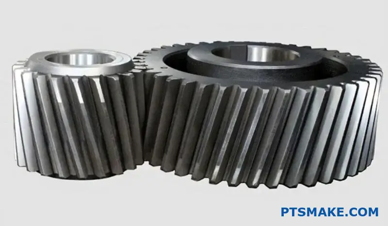
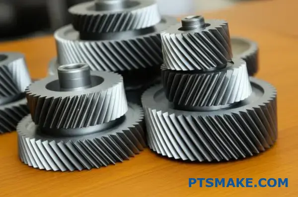
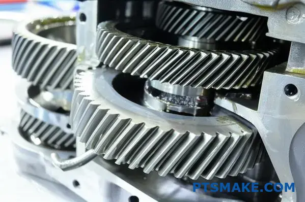
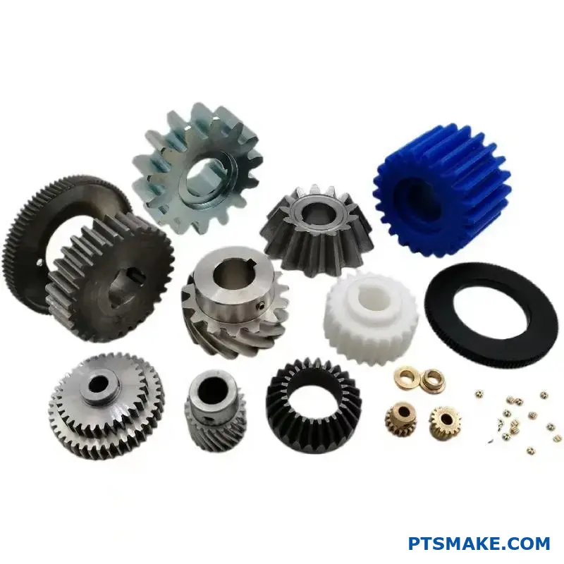
Helical gears are spiral-toothed gears that provide smoother operation, higher load capacity, and reduced noise compared to spur gears, making them ideal for high-performance applications despite introducing axial thrust forces.
This guide breaks down helical gear design into practical steps that you can apply immediately. I’ll walk you through the geometric principles, force calculations, material selection, and manufacturing considerations that determine whether your gear system succeeds or fails in the field.
Why choose helical gears over spur gears?
When designing a power transmission system, the choice between spur and helical gears is fundamental. Each has distinct advantages for specific applications. Spur gears are simpler and create no axial force.
However, helical gears often provide superior performance. They operate more smoothly and quietly. This makes them ideal for high-speed or noise-sensitive machinery.
Core Differences at a Glance
Let’s compare them directly. The primary difference lies in the tooth design, which impacts everything from noise to load capacity.
| Feature | Spur Gears | Helical Gears |
|---|---|---|
| Noise Level | High | Low |
| Load Capacity | Good | Excellent |
| Axial Thrust | None | Yes |
| Efficiency | High | Slightly Lower |
This table shows the basic trade-offs you face.
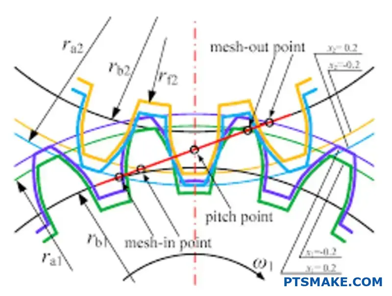
When you look closer, the angled teeth of helical gears are the key. Unlike spur gears, where teeth engage along their entire face at once, helical gear teeth meet at a point and then gradually spread contact.
The Advantage of Angled Teeth
This gradual engagement1 is why they run so smoothly. The load is transferred progressively, which eliminates the sudden impact and "whine" common with spur gears, especially at high speeds. This also increases the contact ratio, meaning more teeth share the load at any given moment.
Higher Load and Power Transmission
Because more teeth are engaged, helical gears can handle higher loads than spur gears of the same size. Our testing shows this allows for more compact and powerful gearbox designs, which is a significant benefit in industries like automotive and aerospace.
The Primary Trade-Off: Axial Thrust
However, there is a major trade-off. The angled teeth create a force along the gear’s axis, known as axial thrust. This force must be managed with appropriate bearings, like thrust bearings. Managing this force is a critical factor in a successful Helical Gears Design.
| Aspect | Spur Gear | Helical Gear |
|---|---|---|
| Engagement | Sudden, full-face | Gradual, progressive |
| Vibration | Higher | Lower |
| Bearing Needs | Simple radial bearings | Radial and thrust bearings |
| Best For | Low-speed, high-noise tolerance | High-speed, low-noise needs |
Helical gears offer smoother, quieter operation with a higher load capacity due to their angled teeth. However, this design introduces axial thrust, a force that requires careful management with specific bearings, adding complexity compared to simpler spur gears.
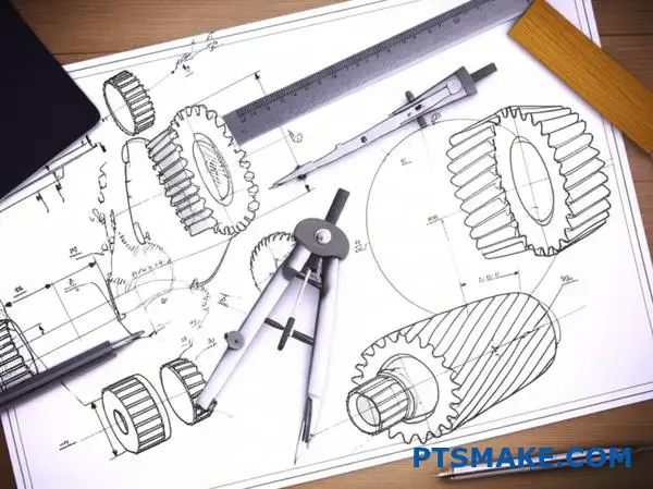
What are the fundamental geometric parameters?
Let’s break down the core of helical gear geometry. It’s all about a few key parameters. These numbers define the gear’s shape. They also control how it interacts with other gears.
Understanding them is essential for successful manufacturing.
Helix Angle: The Defining Twist
The helix angle is the defining feature. It is the angle of the teeth relative to the gear’s axis. This angle allows for smoother, quieter operation compared to spur gears.
Pitch and Module: Sizing the Teeth
Pitch measures the distance between teeth. Module is a metric equivalent that defines tooth size. Getting these right is critical for gears to mesh correctly.
| Parameter | Description |
|---|---|
| Normal Pitch | The distance between teeth measured perpendicular to the tooth. |
| Transverse Pitch | The distance between teeth measured along the pitch circle. |
The Deeper Geometry
Beyond the basics, several other parameters are crucial. They fine-tune the gear’s performance and manufacturability. At PTSMAKE, we focus on these details from the start. This ensures the final part meets exact specifications.
Pressure Angle
The pressure angle affects how force is transmitted. It influences the shape of the tooth profile. A common angle is 20 degrees. However, custom angles can be used for specific load requirements. This is a critical detail in high-performance helical gears design.
Module: Normal vs. Transverse
Just like pitch, the module has two forms. The normal module is measured perpendicular to the tooth. The transverse module is measured in the plane of rotation. Mating helical gears must share the same normal module to mesh properly.
Addendum and Dedendum: Tooth Height
These parameters define the tooth’s height. The addendum is the height above the pitch circle2. The dedendum is the depth below it. Together, they determine the working depth and clearance between meshing teeth.
| Parameter | Function | Impact |
|---|---|---|
| Helix Angle | Defines tooth slant | Smoothness, thrust load |
| Pressure Angle | Tooth profile shape | Force transmission, strength |
| Module | Tooth size | Gear size and strength |
| Addendum | Top portion of tooth | Engagement depth |
| Dedendum | Bottom portion of tooth | Clearance |
Mastering these geometric parameters is fundamental. The helix angle, pitch, pressure angle, and tooth height define the gear’s shape, function, and efficiency. They are the blueprint for high-quality helical gear manufacturing.
What is the function of the helix angle?
The helix angle is not just a random number. It’s a critical design choice. It directly controls how gears perform. This choice involves a careful balancing act.
A larger angle means smoother, quieter operation. But it also creates more axial thrust. A smaller angle handles more load with less thrust. But it can be noisier.
Thinking about the right Helical Gears Design is key. We must weigh these factors for every project.
| Helix Angle | Pros | Cons |
|---|---|---|
| Low (e.g., < 20°) | High load capacity, Low axial thrust | Higher noise, Less smooth |
| High (e.g., > 30°) | Quiet operation, Smooth engagement | Lower load capacity, High axial thrust |
Choosing the Right Angle for the Job
Selecting the perfect helix angle is crucial. It entirely depends on the specific application’s demands. There is no one-size-fits-all answer here.
At PTSMAKE, we guide clients through this process. We help them find the optimal balance for their needs. This ensures performance and longevity.
High-Speed Applications
For high-speed systems, like automotive transmissions, we often use larger helix angles. An angle between 30° and 45° is common.
This choice ensures a smoother transfer of power. A higher angle increases the contact ratio3, which significantly reduces noise and vibration. The trade-off is higher axial thrust. This force must be managed with robust bearings.
High-Load Applications
In contrast, industrial machinery often prioritizes strength. Here, a smaller helix angle, typically 15° to 25°, is better.
This design maximizes the load-carrying capacity. It also keeps the axial thrust manageable, reducing stress on the system. Our findings show this approach improves durability in heavy-duty environments.
| Application Example | Typical Helix Angle | Primary Goal |
|---|---|---|
| Automotive Gearbox | 30° – 45° | Noise Reduction |
| Industrial Conveyor | 15° – 25° | Load Capacity |
| Precision Robotics | 20° – 35° | Balance of Smoothness & Strength |
The helix angle is a core element in helical gear design. It directly influences load capacity, noise, and axial thrust. Choosing the optimal angle is a critical trade-off tailored to each specific application’s performance requirements.
What forces act on a helical gear?
When helical gears mesh, a single resultant force acts on the tooth surface. For practical design, we break this force down into three distinct components.
This approach simplifies analysis. It allows us to predict how the gear will behave under load. Understanding these vectors is fundamental.
Each component has a specific direction and impacts the gear, shaft, and bearings differently.
The Three Core Force Components
Here is a quick breakdown of each force vector:
| Force Component | Primary Function/Effect |
|---|---|
| Tangential | Transmits torque and power |
| Radial | Pushes the gears apart from each other |
| Axial (Thrust) | Pushes the gear along its shaft axis |
Properly managing these forces is key to a reliable system.
Why These Forces Matter in Design
Calculating these forces is more than a textbook exercise. It has direct consequences for the entire mechanical assembly. Neglecting one component can lead to system failure.
At PTSMAKE, our process for Helical Gears Design always starts with a thorough force analysis.
Tangential Force (Wt)
This is the workhorse component. It’s the force that actually transmits power from one gear to the other. You can calculate it directly from the torque and the gear’s pitch diameter.
Radial Force (Wr)
This force acts toward the center of the gear. It tries to push the two meshing gears apart. This load must be supported by the shaft bearings. Incorrectly specified bearings will wear out quickly under high radial loads.
Axial Force (Wa)
Also known as thrust, this is unique to helical gears. It acts parallel to the gear’s axis of rotation. This force requires thrust bearings or angular contact bearings to prevent the gear from moving along the shaft. A key factor is the normal pressure angle4, which helps determine the magnitude of these forces.
| Force | Design Consideration | Potential Failure Mode |
|---|---|---|
| Tangential | Shaft strength, keyway design | Tooth shear, shaft torsion failure |
| Radial | Bearing selection, shaft deflection analysis | Premature bearing wear, fatigue |
| Axial | Thrust bearing selection, housing strength | Bearing overheating, gear misalignment |
In past projects, we’ve found that overlooking the axial thrust is a common source of failure in initial prototypes from less experienced teams.
Understanding the three force components—tangential, radial, and axial—is critical. This knowledge directly informs the design of robust shafts and the selection of appropriate bearings, preventing catastrophic mechanical failures and ensuring long-term reliability for your application.
What are the main types of helical gear arrangements?
Helical gear arrangements are primarily defined by the orientation of their shafts. Understanding these configurations is key for effective Helical Gears Design.
The two main types are parallel axis and crossed-axis arrangements. Each serves a distinct purpose.
Key Arrangement Types
Your choice depends entirely on whether the shafts you need to connect are parallel or not. This is a fundamental decision in gear system design.
| Arrangement Type | Shaft Orientation | Primary Contact |
|---|---|---|
| Parallel Axis | Parallel | Line Contact |
| Crossed-Axis | Non-Parallel, Non-Intersecting | Point Contact |
This basic difference influences everything from efficiency to load capacity.
When designing a gear system, the shaft layout is the first constraint you must address. This dictates which type of helical gear arrangement is even possible for your application. At PTSMAKE, we always start here.
Parallel Axis Arrangements
These are the most common. They transmit power between two parallel shafts. For external gears to mesh properly, they must have opposite-hand helices (one right-hand, one left-hand). This configuration is highly efficient and can handle significant loads. It is the backbone of many industrial transmissions and speed reducers.
Crossed-Axis Arrangements
Also known as screw gears, these connect two non-parallel, non-intersecting shafts. A unique feature is that the gears can have the same hand (both right-hand or both left-hand).
However, their contact is theoretically a single point. This limits their load-carrying capacity. Efficiency is also lower due to higher sliding friction. The forces generated, such as axial thrust5, also require careful management in the bearing design.
Application and Limitation Comparison
Let’s break down where each type excels and its limitations.
| Type | Common Applications | Key Limitations |
|---|---|---|
| Parallel Axis | Automotive transmissions, industrial gearboxes, speed reducers | Can only be used for parallel shafts |
| Crossed-Axis | Automotive steering mechanisms, light-duty instrument drives | Lower efficiency, limited load capacity, higher wear |
In past projects, we’ve found crossed-axis gears are best for motion transfer, not high-power transmission.
Helical gear arrangements are categorized into two main types: parallel axis and crossed-axis. The choice is determined by shaft orientation, with parallel arrangements offering higher efficiency and load capacity, while crossed-axis setups provide unique geometric flexibility for non-parallel shafts.
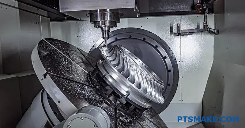
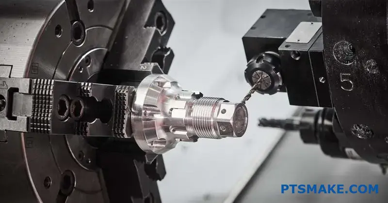
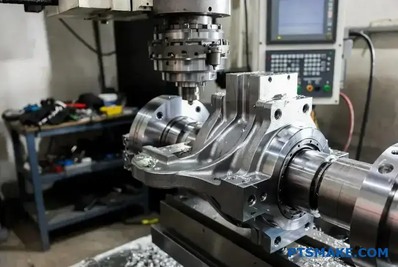
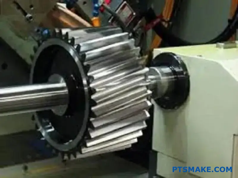
How are helical gears classified by manufacturing process?
Choosing the right manufacturing process is a critical decision. It directly impacts your gear’s performance, cost, and lead time. The method truly defines the final product.
We mainly consider four common methods. These are hobbing, shaping, milling, and grinding. Each has its place in helical gears design.
Let’s look at a quick comparison.
| Process | Best For | Speed |
|---|---|---|
| Hobbing | High Volume | Fast |
| Shaping | Internal Gears | Medium |
| Milling | Prototypes | Slow |
| Grinding | High Precision | Slow |
Let’s break down these methods further. The best choice always depends on your specific application needs. It’s a careful balance of quality, speed, and budget.
Hobbing: The Workhorse
Hobbing is a continuous generating process. This makes it very fast and cost-effective for medium to large production runs. It produces high-quality gears suitable for most industrial applications. The process is highly efficient.
Milling and Shaping: Versatility
Milling uses a form cutter that matches the tooth space. It’s slower than hobbing but very versatile for prototypes or small batches. Shaping is ideal for creating internal gears or gears with features that restrict cutter clearance.
Grinding: The Finishing Touch
Grinding is typically a finishing operation. It is used after a gear has been rough-cut and heat-treated. This process delivers exceptional accuracy and a superior surface finish. It ensures the precision of the involute profile6 is nearly perfect. In past projects at PTSMAKE, we used grinding for aerospace parts where precision is non-negotiable.
Here is a more detailed comparison based on our test results.
| Process | Precision Level | Surface Finish | Production Speed | Relative Cost |
|---|---|---|---|---|
| Milling | Low | Rough | Slow | Low |
| Shaping | Medium | Fair | Medium | Medium |
| Hobbing | High | Good | Fast | Medium |
| Grinding | Very High | Excellent | Slow | High |
Selecting a manufacturing process is a crucial design decision. It dictates the helical gear’s final precision, surface finish, production speed, and overall cost. Aligning the method with your application’s specific demands ensures the best possible outcome for your project.
How do material choices structure the design process?
Choosing the right gear material is a critical first step. It’s a balance of performance, manufacturability, and cost. This choice sets the stage for the entire project.
Your decision here impacts everything that follows. It defines the limits and possibilities of your design.
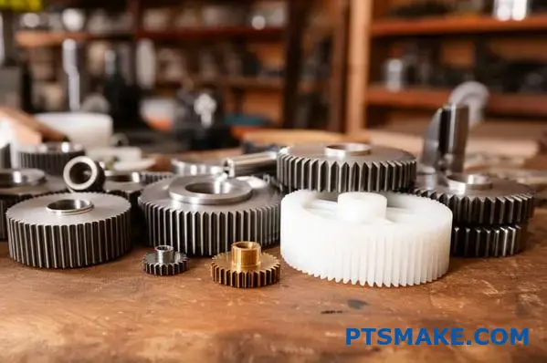
An Overview of Common Materials
We can group most gear materials into a few key categories. Each family has distinct advantages and trade-offs to consider.
| Material Group | Key Characteristic | Best For |
|---|---|---|
| Steels | High Strength & Durability | Industrial Machinery |
| Plastics | Low Noise & Self-Lubricating | Consumer Products |
| Bronzes | Low Friction & Conformability | Worm Gear Drives |
Understanding these groups is essential for effective design.
Diving Deeper into Material Properties
Let’s explore each category more closely. The specifics of your application will guide you to the best option. At PTSMAKE, we help clients navigate these choices daily.
Steels: The Powerhouses
Steels are the most common choice for gears. Low-carbon steels are easily machined but may need surface hardening. Medium-carbon steels offer a good mix of strength and toughness.
Alloy steels are the top performers. They are used for high-stress applications, including robust helical gears design. Heat treatment is key to unlocking their full potential. This adds a step but dramatically boosts performance.
Plastics: Quiet and Efficient
Engineering plastics like Nylon and Acetal (Delrin) are fantastic. They are perfect for light-to-moderate loads where low noise is crucial. Think office printers or medical devices.
Their self-lubricating properties reduce maintenance needs. Plus, injection molding makes them cost-effective for high-volume production, a process we specialize in.
Bronzes: The Ideal Partner
Bronze alloys have a unique role. They are often used for worm gears that run against a steel worm. This is because bronze is a softer, conformable material.
This pairing prevents galling and reduces friction. Manufacturing often involves casting or sintering7, a process that can create porous parts capable of holding lubricant.
| Material Category | Relative Strength | Relative Cost | Key Advantage |
|---|---|---|---|
| Carbon & Alloy Steels | Very High | Medium – High | Durability under load |
| Engineering Plastics | Low – Medium | Low | Quiet, no lubrication |
| Bronze Alloys | Medium | High | Low friction with steel |
Material selection is a fundamental design trade-off. Steels offer unmatched strength, plastics provide quiet and low-cost operation, and bronzes excel in specific low-friction roles. Your application’s unique demands will determine the best path forward.
What lubrication types exist for helical gear systems?
Choosing the right lubrication method is critical. It directly impacts the efficiency and lifespan of your helical gears. The method isn’t one-size-fits-all.
It depends on your specific application. Key factors include operating speed, load, and temperature. Let’s explore the common options.
Key Lubrication Methods
We generally consider three main types. Each has its place in a proper Helical Gears Design.
| Lubrication Method | Primary Use Case | Complexity |
|---|---|---|
| Oil Splash/Bath | Moderate speed & load | Low |
| Forced Oil Circulation | High speed & heavy load | High |
| Grease | Low speed & sealed units | Low |
Oil Splash vs. Forced Oil vs. Grease
Let’s break down each method. Understanding the pros and cons helps you make a better choice. In our projects at PTSMAKE, this is a frequent topic of discussion.
Oil Splash/Bath Systems
This is the simplest method. Gears dip into an oil reservoir, splashing oil onto other components. It’s cost-effective and reliable for many general-purpose applications.
However, at high speeds, it causes "churning." This leads to excessive heat and power loss. It’s not ideal for high-performance systems.
Forced Oil Circulation
This method uses a pump. It sprays a continuous stream of cooled, filtered oil directly onto the gear mesh. This is the top choice for demanding jobs.
It excels at heat dissipation. This makes it perfect for high-speed and heavy-load conditions where temperatures can soar. The main drawback is its complexity and cost.
Forced oil systems are essential when the pitch-line velocity8 is high, ensuring a stable oil film protects the gear teeth from wear.
Grease Lubrication
Grease is best for sealed gearboxes. It’s also great for applications that are difficult to access for regular maintenance. It adheres well to surfaces.
Its main weakness is poor heat transfer. Grease can’t cool the gears like oil can. It’s best suited for low-speed, intermittent, or lightly loaded applications.
| Method | Pros | Cons |
|---|---|---|
| Oil Splash | Simple, low cost | Poor heat dissipation, speed limited |
| Forced Oil | Excellent cooling & filtration | Complex, high cost, needs power |
| Grease | Stays put, low maintenance | Poor cooling, can harden over time |
Selecting the right method is a balance. You must weigh performance needs against system complexity and cost. Your choice directly impacts gear longevity. It ensures your helical gear system operates as designed under its specific working conditions.
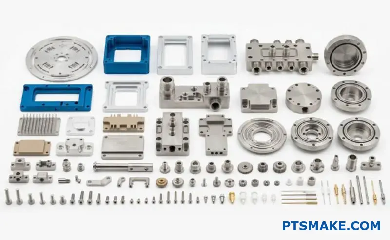
What are the key elements of a gear specification sheet?
A detailed manufacturing drawing is the final output of your design process. It is the single source of truth for production.
This document must clearly communicate every critical detail. Without it, you risk costly errors and delays. It bridges design intent with manufacturing reality.
Fundamental Gear Data
The core parameters define the gear’s basic geometry. These must be precise and unambiguous.
| Parameter | Description |
|---|---|
| Number of Teeth (Z) | Defines the gear’s size and ratio. |
| Module (m) | The ratio of the reference diameter to the number of teeth. |
| Pressure Angle (α) | The angle of force transmission between teeth. |
| Helix Angle & Hand (β) | For helical gears, defines the tooth angle and direction (Left/Right). |
Material and Quality
These specs dictate the gear’s performance and lifespan. They include the specific material, any required heat treatment, and the expected quality level.
The information on a drawing goes far beyond basic numbers. Every detail has a purpose, directly impacting the final part’s function, durability, and cost. Missing just one element can cause major problems down the line.
Critical Manufacturing Tolerances
Tolerances define the acceptable variation for each dimension. Tight tolerances are essential for high-precision applications but increase manufacturing costs. At PTSMAKE, we help clients balance performance needs with production feasibility. Clear tolerances on tooth profile, lead, and pitch are crucial. This is especially true in complex Helical Gears Design.
Heat Treatment and Surface Finish
The material choice is just the start. Specifications for heat treatment, like carburizing or nitriding, are vital for achieving the required hardness and wear resistance. Surface finish requirements also impact performance and friction. An often overlooked detail is the addendum modification coefficient9, which is crucial for preventing tooth interference in specific gear pairs.
The required quality level, often defined by standards like AGMA or ISO, dictates the inspection process. It ensures the gear meets the demands of its application.
| Quality Level (AGMA) | Typical Application |
|---|---|
| Q5 – Q7 | General industrial machinery, toys. |
| Q8 – Q10 | Automotive transmissions, machine tools. |
| Q11 – Q13 | Aerospace, high-speed power transmission. |
| Q14 – Q15 | Master gears, precision instrumentation. |
Getting these specifications right on the drawing is non-negotiable. It is the blueprint we use to turn your design into a reliable, high-performance component.
A complete manufacturing drawing is the ultimate communication tool. It ensures that the design engineer’s vision is perfectly translated into a physical part, eliminating ambiguity and preventing costly production mistakes.
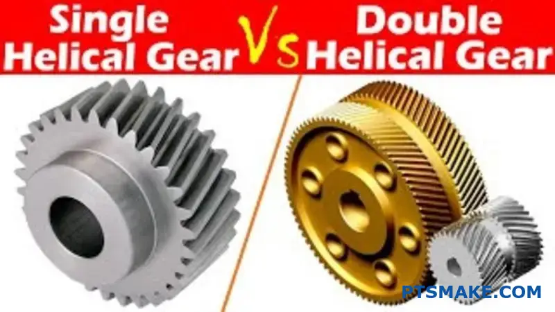
How do single vs. double helical (herringbone) gears compare?
Choosing between single and double helical gears is a major design choice. It’s a classic engineering trade-off between performance and cost.
Double helical, or herringbone, gears have a unique advantage. They inherently cancel out axial thrust. This allows for higher helix angles.
The result is smoother, quieter power transmission. But this benefit comes at a price. They are much more complex and expensive to manufacture. This is a key aspect of helical gears design.
Key Trade-Offs at a Glance
| Feature | Single Helical Gear | Double Helical (Herringbone) Gear |
|---|---|---|
| Axial Thrust | Generates thrust | Self-canceling |
| Operation | Smooth | Exceptionally smooth and quiet |
| Cost | Lower | Significantly higher |
| Complexity | Simpler to make | Complex to manufacture |
The Core Design Choice: Thrust vs. Complexity
The fundamental difference comes down to axial thrust. A single helical gear pushes sideways along its axis as it turns. This force must be managed with robust thrust bearings. These bearings add cost and complexity to the overall assembly.
Double helical gears solve this problem elegantly. They are essentially two single helical gears mirrored together. The thrust from one side perfectly cancels the thrust from the other. This self-contained design eliminates the need for external thrust management.
Performance Gains of Double Helical Gears
Because axial thrust is no longer a concern, engineers can use much higher helix angles. A higher angle means more teeth are in contact at any given moment. This increases the load-carrying capacity and ensures a smoother transfer of power. The result is less vibration and quieter operation.
The Manufacturing Challenge
This superior performance comes with significant manufacturing hurdles. Creating the opposing helices with perfect alignment is difficult. Gear cutting processes like hobbing10 require special tooling or multiple setups.
Any misalignment between the two halves can reintroduce stress. This negates the benefits of the design. At PTSMAKE, we use advanced CNC machines to ensure this critical precision. This precision directly translates to higher manufacturing costs.
| Aspect | Single Helical | Double Helical |
|---|---|---|
| Bearing Needs | Requires thrust bearings | No thrust bearings needed |
| Helix Angle | Limited by thrust | Can be higher for smoothness |
| Manufacturing | Standard processes | Specialized machinery/setups |
| Application | General purpose | High-torque, high-speed |
The choice is clear: double helical gears offer superior performance by eliminating axial thrust for smoother operation. However, this comes at a significant cost premium due to their complex manufacturing requirements. It’s a trade-off between ideal performance and budget reality.
What role does surface treatment play in gear life?
Surface treatments are the final, crucial step. They determine a gear’s resilience against wear and fatigue. Think of it as armor for your component.
We generally group these techniques into two main categories. The choice depends entirely on the gear’s application and material.
Hardening Categories
The main distinction is how deep the hardening goes. Does the entire gear need to be hard, or just the surface?
| Hardening Type | Core Property | Surface Property |
|---|---|---|
| Through-Hardening | Hard | Hard |
| Case-Hardening | Tough & Ductile | Hard & Wear-Resistant |
This choice is fundamental to performance.
Case-hardening is often the superior choice for gears. It creates a dual-property component. You get a very hard, wear-resistant surface with a softer, tougher core.
This combination prevents surface wear from contact stress. At the same time, the ductile core absorbs shock loads without fracturing. It’s the best of both worlds. The process involves heating the steel to transform its structure into austenite11 before quenching.
Common Case-Hardening Methods
At PTSMAKE, we often work with three primary methods. Each has unique benefits for applications like high-stress helical gears design.
Carburizing
This method introduces carbon into the steel’s surface. It creates a very hard and deep case, ideal for heavy-duty applications. However, it can cause some part distortion.
Nitriding
Nitriding uses nitrogen to harden the surface. It results in extremely high surface hardness. The process occurs at lower temperatures, minimizing distortion. This makes it perfect for precision gears.
Induction Hardening
This technique uses electromagnetic induction to heat the surface. It’s fast and precise. It is excellent for localized hardening on specific gear tooth areas.
| Method | Key Advantage | Best For |
|---|---|---|
| Carburizing | Deep, hard case | High impact loads |
| Nitriding | High hardness, low distortion | Precision components |
| Induction Hardening | Fast, localized control | Complex gear geometries |
Surface treatments are divided into through-hardening and case-hardening. Case-hardening methods like carburizing, nitriding, and induction hardening create a hard, wear-resistant surface while keeping a tough core. This dual nature significantly extends gear operational life and reliability.
How do you perform basic geometric design calculations?
Geometric design calculations are a systematic process. You begin with core requirements. These are usually the gear ratio and the center distance between shafts.
From these starting points, we methodically determine all other critical parameters. It’s a puzzle where each piece must fit perfectly.
Key Starting Constraints
Your entire design hinges on two primary values.
| Constraint | Description |
|---|---|
| Required Ratio | The speed and torque relationship between the two gears. |
| Center Distance | The fixed distance between the centers of the two shafts. |
This structured approach ensures your final design meets all operational needs without fail. It prevents costly errors later.
To get from initial requirements to a final design, you must follow a clear, iterative methodology. It is not always a straight line from A to B. You often need to adjust parameters to meet all constraints.
Step-by-Step Calculation Guide
First, we establish our knowns: the gear ratio (i) and center distance (a). The goal is to find the right combination of module, teeth numbers, and helix angle that fits these constraints.
Initial Parameter Selection
The helix angle (β) is often a good starting point for helical gears design. A common choice is between 15° and 30°. This choice directly influences the gear’s strength and noise level.
Based on our testing, a larger helix angle provides smoother operation. However, it also creates more axial thrust, which must be considered.
The Iterative Loop
With a trial helix angle, we can then approach the module. The transverse module (mt) is tied to the center distance, while the Normal Module12 relates to the cutting tool. They are linked by the helix angle.
The process involves selecting a standard module and calculating the number of teeth. You adjust until the numbers work out to integers that satisfy the gear ratio and fit the exact center distance.
| Parameter | Relationship / Goal |
|---|---|
| Pitch Diameters | Determined by module and teeth number. |
| Number of Teeth | Must be integers and satisfy the gear ratio. |
| Face Width | Sized to handle the required torque load. |
At PTSMAKE, we use software to speed this up, but understanding the manual process is key for any engineer. It ensures you can sanity-check the results.
This step-by-step process, starting from ratio and center distance, provides a reliable framework. It guides you through the interconnected choices of module, teeth number, and helix angle to create a functional and robust geometric design for components like helical gears.
How to select appropriate materials and heat treatment?
A structured decision-making framework is key. It removes guesswork from material selection. This process ensures your gears meet performance demands reliably.
Start with Stress Calculations
First, you must understand the forces at play. Calculate the bending and contact stresses your gear will face during operation. These numbers are your foundation.
Use Material Property Charts
With stress values in hand, consult material charts. Standards from organizations like AGMA are invaluable here. They map out material properties.
The goal is to find a steel alloy and heat treatment combination. This pairing must offer sufficient allowable stress. It should also include a proper safety margin.
| Stress Type | Key Consideration |
|---|---|
| Bending Stress | Relates to tooth fracture resistance |
| Contact Stress | Relates to surface pitting resistance |
This systematic approach leads to a durable and reliable final product.
A Framework for Selection
A robust framework prevents costly errors. After calculating stresses, the next step is a deep dive into material properties. You are looking for a material that can handle the calculated loads over its entire service life.
The Role of Safety Margins
A safety margin is not just an arbitrary buffer. It accounts for uncertainties in load calculations, material inconsistencies, and manufacturing variations. A margin of 1.5 to 2.0 is common, but this can vary.
Matching Material to Application
We often use AGMA charts at PTSMAKE to guide this process. These charts provide allowable stress numbers for various steel alloys and heat treatments. This data helps us compare options quickly.
For example, your calculations might point to a need for high surface hardness. This would lead you to consider case-hardening processes. This is a critical aspect of durable Helical Gears Design.
The material’s endurance limit13 is a critical factor in this analysis. It determines how the material withstands repeated stress cycles without failing.
| Material | Common Heat Treatment | Key Benefit |
|---|---|---|
| AISI 4140 | Quenched & Tempered | Good core strength, moderate cost |
| AISI 8620 | Carburized & Hardened | Excellent surface hardness, good toughness |
| AISI 9310 | Carburized & Hardened | Premium performance, high fatigue life |
This structured comparison ensures we select the optimal balance of performance and cost.
A solid framework starts with stress analysis. It then uses material charts for selection. Finally, it always includes a safety margin. This ensures reliable performance and longevity for your parts.
Understanding Heat Treatment Options
Selecting the alloy is only half the battle. The heat treatment process is what truly unlocks the material’s potential. Each method offers a unique balance of properties.
Carburizing and Hardening
This is a case-hardening process. We introduce carbon into the surface of a low-carbon steel part. This creates a hard, wear-resistant outer layer (the "case").
The core of the tooth remains softer and more ductile. This combination provides excellent resistance to surface fatigue while maintaining toughness to absorb shock loads without fracturing.
Nitriding
Nitriding is another surface-hardening process. It uses nitrogen to create a very hard surface layer. It’s done at lower temperatures than carburizing, which results in less part distortion. This makes it ideal for high-precision gears.
Through-Hardening
This process, often called quenching and tempering, hardens the entire gear tooth, not just the surface. It provides good overall strength and toughness. It’s generally a more cost-effective option for applications with moderate loads.
| Treatment | Surface Hardness | Core Toughness | Distortion Risk |
|---|---|---|---|
| Carburizing | Very High | Good | Moderate |
| Nitriding | High | Varies | Low |
| Through-Hardening | Moderate | Good | Moderate |
In our work with clients, we analyze the application’s specific needs to recommend the most suitable and cost-effective heat treatment.
Making the Final Decision
Choosing the right material and heat treatment is a critical step. It directly impacts the gear’s lifespan, reliability, and overall cost. A systematic approach is not just recommended; it’s essential.
Start with your engineering calculations. Let the data on bending and contact stress guide you.
Use industry-standard charts to narrow your options. Always factor in a conservative safety margin to ensure long-term performance.
This methodical process removes ambiguity. It ensures your final choice is based on solid engineering principles. At PTSMAKE, we use this framework to deliver parts that perform flawlessly from day one.
How to determine the required gear quality level?
Choosing the right gear quality is a critical decision. It directly impacts performance, lifespan, and overall cost. You are essentially balancing precision against your budget.
This choice isn’t arbitrary. It’s guided by specific operational factors. Higher speeds demand tighter tolerances to function correctly.
Key Deciding Factors
Consider three main points: speed, noise, and how critical the application is. A mismatch here can lead to premature failure or unnecessary expense.
| Factor | Low Requirement | High Requirement |
|---|---|---|
| Operating Speed | Lower AGMA/ISO Quality | Higher AGMA/ISO Quality |
| Noise Level | Lower AGMA/ISO Quality | Higher AGMA/ISO Quality |
| Criticality | Lower AGMA/ISO Quality | Higher AGMA/ISO Quality |
A higher quality number from AGMA or ISO means tighter tolerances. This precision reduces errors in motion, vibration, and noise. But it also increases manufacturing complexity and cost.
Finding the sweet spot is key. Over-specifying a gear quality level means you pay for precision you don’t need. Under-specifying leads to poor performance and potential system failure.
Balancing Cost and Performance
The cost increase is not linear. Moving from an AGMA 8 to an AGMA 10 can raise costs significantly. Jumping to AGMA 12 or higher requires specialized grinding and inspection, further increasing the price.
The Role of Operating Speed
High-speed systems are sensitive to imperfections. Even a small error, like pitch deviation14, can cause significant vibration and noise at high RPMs. This is especially true in applications involving helical gears design, where smooth power transmission is paramount. For speeds over 2000 RPM, a higher quality grade is usually necessary.
Noise and Criticality
Some applications demand quiet operation. Medical devices or high-end consumer electronics are great examples. Here, a higher gear quality is non-negotiable.
In aerospace or robotics, failure is not an option. The gear’s criticality dictates a very high quality level, regardless of speed or noise, to ensure absolute reliability.
| Application Type | Typical AGMA Quality Range |
|---|---|
| Consumer Goods | 6 – 8 |
| Industrial Machinery | 8 – 10 |
| Automotive / EV | 9 – 11 |
| Aerospace / Medical | 11 – 13+ |
Selecting the right gear quality is a trade-off. You must carefully weigh operating speed, noise constraints, and application criticality against manufacturing costs. A methodical approach prevents over-engineering and ensures you get the performance you need without overpaying for unnecessary precision.
A Practical Selection Method
In past projects, I’ve found a simple, three-step approach works best. This method helps teams avoid confusion and make a data-driven decision.
First, clearly define your non-negotiable performance requirements. What is the maximum acceptable noise level? What are the operational speeds and loads?
Second, use these requirements to identify a starting quality range from AGMA or ISO charts. This gives you a technical baseline for discussion.
Finally, talk with your manufacturing partner. At PTSMAKE, we can review your design and suggest the most cost-effective quality level that meets your performance targets, preventing costly rework later.
Why Partnership Matters
These standards are excellent guidelines, but they are not the whole story. Real-world performance depends on the manufacturing process, material selection, and assembly.
This is where a strong partnership with your manufacturer becomes invaluable. An experienced team can look beyond the numbers. We can help you understand the practical implications of choosing an AGMA 9 over an AGMA 10 for your specific design, potentially saving you thousands on a production run.
Final Considerations
Ultimately, your goal is to specify the lowest quality level that reliably meets all of your application’s performance requirements. Don’t fall into the trap of thinking "higher is always better."
Better is what works perfectly for your project and your budget. It’s a strategic choice, not just a technical one. Collaborating with experts ensures you make the right choice from the start.
Unlock Precision Helical Gear Solutions with PTSMAKE
Whether you’re designing advanced helical gears or need reliable, high-precision gear manufacturing, PTSMAKE is ready to bring your project to life. Contact us today for a fast, no-obligation quote and discover why leading engineers and innovators trust PTSMAKE for their toughest challenges!

Discover the mechanics of how angled teeth improve gear performance and reduce noise. ↩
Click for a visual guide to better understand this foundational gear concept. ↩
Understand how this key metric influences gear performance and longevity in detailed Helical Gears Design. ↩
Learn more about how this angle impacts gear force calculations and overall performance. ↩
Learn how this force impacts bearing selection and overall design in our detailed guide. ↩
Understand this critical gear tooth curve and its impact on performance and efficiency. ↩
Learn more about this powder metallurgy process that creates strong, self-lubricating parts for specialized uses. ↩
Learn how this critical parameter impacts your gear design and lubrication choices. ↩
Discover how this factor is adjusted to improve gear mesh and prevent undercutting. ↩
Learn about this common gear cutting method and its challenges with complex geometries. ↩
Learn about this critical high-temperature phase of steel and its role in heat treatment. ↩
Understand the crucial difference between normal and transverse module for accurate helical gear calculations. ↩
Learn how this critical property determines the long-term fatigue life of your parts. ↩
Click to understand how this tiny variation impacts gear noise and overall performance. ↩