Heat sinks fail more often than you think. I see engineers struggle with overheating electronics, unexpected thermal shutdowns, and designs that work on paper but fail in real applications.
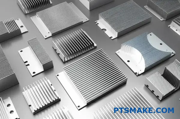
Effective heat sink design requires understanding material properties, manufacturing methods, and system-level thermal management to match cooling solutions with specific performance, cost, and space constraints.
This guide walks you through 23 critical questions that determine whether your thermal solution succeeds or fails. You’ll learn the practical trade-offs between materials, manufacturing methods, and cooling approaches that experienced thermal engineers use to solve real-world problems.
How does material choice impact heat sink effectiveness?
Choosing the right material for a heat sink is crucial. It’s a balance of performance, cost, and weight. Your decision directly impacts thermal management.
The key metric here is thermal conductivity (k value). It tells you how efficiently a material transfers heat.
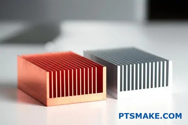
Let’s compare the two most common materials. Copper is an excellent conductor but is heavier and more expensive. Aluminum offers good performance at a lower cost and weight.
Here’s a quick comparison:
| Material | Thermal Conductivity (W/mK) | Relative Cost | Density (g/cm³) |
|---|---|---|---|
| Copper | ~400 | Higher | 8.96 |
| Aluminum (6061) | ~167 | Lower | 2.70 |
This trade-off is central to effective heat sink design.
The choice between aluminum and copper isn’t always straightforward. It goes beyond the numbers on a spec sheet.
The Case for Copper
Copper’s high thermal conductivity makes it ideal for high-power applications. If you have a small space and need to move a lot of heat quickly, copper is often the best choice. Think of high-performance CPUs or compact power electronics. The higher cost and weight are justified by the superior performance in these critical situations.
The Advantage of Aluminum
For most applications, aluminum alloys like 6061 or 6063 are fantastic. Their thermal conductivity1 is lower than copper’s, but it’s more than sufficient for many electronics. The real win comes from its low density and cost. In our past projects at PTSMAKE, we’ve found that for larger heat sinks, the weight savings from aluminum are a major design advantage. It’s also much easier to extrude, allowing for complex fin designs that improve airflow and cooling.
Making the Right Decision
Ultimately, the best material depends on the specific product requirements. You must consider the thermal load, the physical space available, the overall product weight limit, and, of course, the budget. In some hybrid designs, we even use copper bases with aluminum fins to get the best of both worlds.
The ideal heat sink material is a trade-off. You must balance thermal conductivity against practical factors like weight and cost. The final choice depends entirely on your specific application’s needs and constraints.
How are heat sinks categorized by manufacturing method?
The manufacturing method is the most fundamental way to classify a heat sink. It dictates everything. It defines the shape, performance, and cost.
Understanding these methods helps you choose the right solution for your project. Each process creates a distinct form factor.
Common Manufacturing Methods
Let’s look at the primary techniques used in the industry. These range from simple extrusions to more complex forging and skiving processes.
A Quick Comparison
| Method | Primary Advantage | Typical Form |
|---|---|---|
| Extrusion | Cost-Effective | Straight Fins |
| Stamping | High Volume | Thin Metal Fins |
| Forging | Structural Integrity | Pin Fins |
| Skiving | High Fin Density | Ultra-Thin Fins |
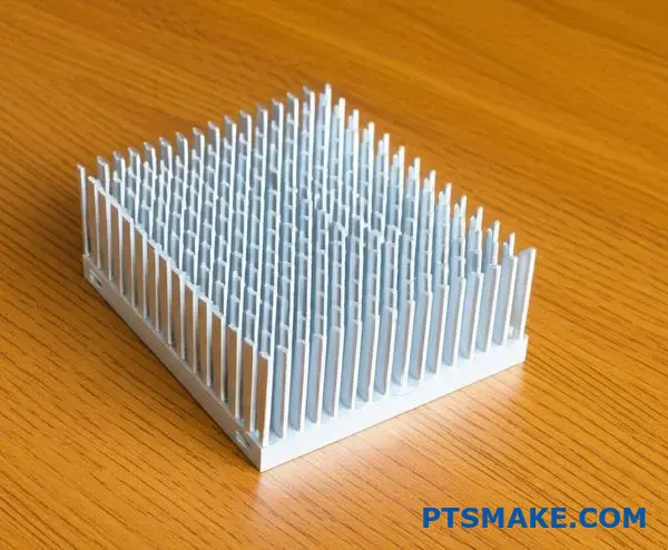
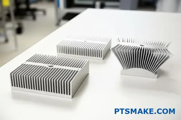
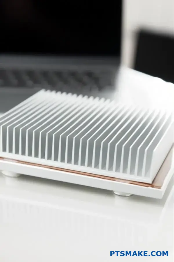
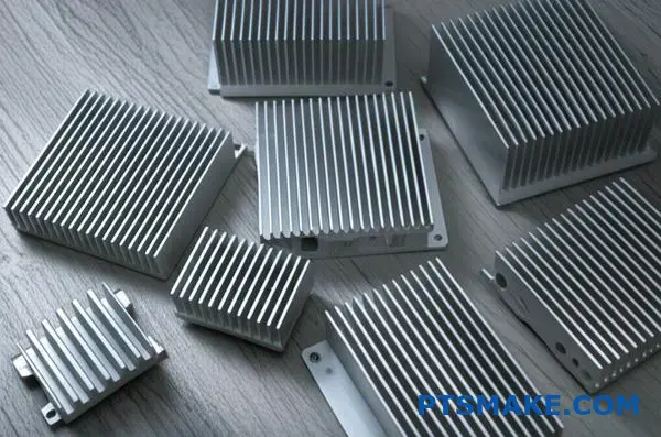
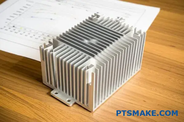
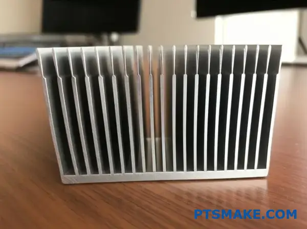
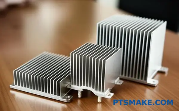
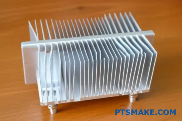
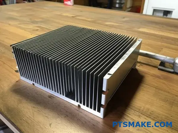
Extrusion
This is the most common method. A block of aluminum is pushed through a die to create a specific cross-sectional profile. This produces heat sinks with straight, linear fins. It is highly cost-effective for medium-power applications.
Stamping
For high-volume production, stamping is a go-to method. Thin sheets of metal, like aluminum or copper, are stamped into desired fin shapes. These fins are then assembled onto a base plate. This is common in consumer electronics.
Forging
Forging involves compressing metal under immense pressure. This creates very strong and intricate shapes, like elliptical or round pin fins. This process improves the material’s structural integrity and enhances its thermal conductivity2. It’s excellent for demanding applications.
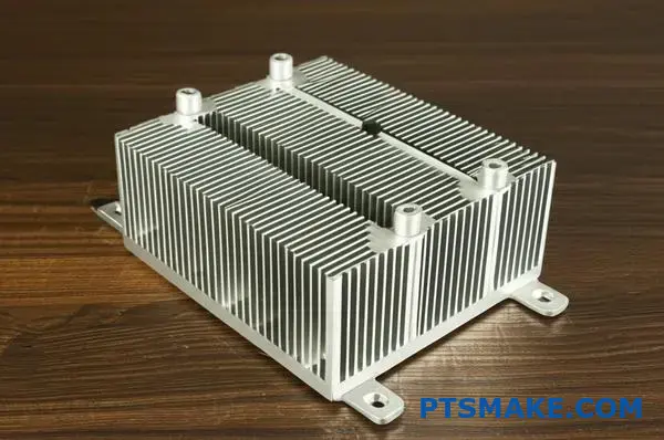
Bonding and Skiving
Bonding allows for a high degree of customization. Fins are manufactured separately and then attached to a base. This lets us build large heat sinks with very high fins. Skiving shaves fins from a solid block of metal, creating a seamless part with extremely high fin density for maximum cooling.
| Process | Design Complexity | Thermal Performance |
|---|---|---|
| Extrusion | Low | Good |
| Stamping | Low to Medium | Moderate |
| Forging | High | Very Good |
| Bonding/Skiving | High | Excellent |
Each manufacturing method produces a heat sink with distinct characteristics. The choice between extrusion, stamping, forging, or skiving depends entirely on your project’s thermal requirements, budget, and the physical constraints of your design.
What are tradeoffs between different manufacturing types?
Choosing the right manufacturing process is critical. It directly impacts your product’s final performance and cost. It’s not just about making a part; it’s about making the right part.
Let’s compare two common methods for a heat sink.
Extrusion: The Workhorse
Extrusion is cost-effective for high volumes. It creates a single piece, which is great for thermal transfer. But it has limits.
Bonded Fin: The Specialist
This method allows for much higher fin density. It gives engineers more design freedom. However, this comes at a higher unit cost.
Here’s a quick look at how they stack up.
| Feature | Extrusion | Bonded Fin |
|---|---|---|
| Tooling Cost | High | Low to Medium |
| Unit Cost | Low | High |
| Design Freedom | Limited | High |
This simple choice sets the stage for everything that follows.
Let’s break down the practical design factors. The manufacturing choice you make has real consequences for your product’s capabilities. We need to go beyond the basics of cost.
Fin Density and Aspect Ratio
Extrusion limits how close fins can be. The process requires a certain base thickness. This also caps the aspect ratio—how tall a fin can be relative to its width. A low aspect ratio can limit cooling.
Bonded fin processes overcome this. We can attach very thin, tall fins to a base. This dramatically increases the surface area for heat dissipation. This is crucial for high-power applications where space is tight. The interstitial3 material used in bonding is also a key factor.
Cost vs. Thermal Performance
This is the central tradeoff. At PTSMAKE, we help clients navigate this decision constantly. For a standard heat sink, extrusion is often sufficient and economical.
When performance is paramount, bonded fins are superior. While the process is more complex and costly, the thermal performance can be significantly better. Based on our tests, a well-designed bonded fin heat sink can outperform an extruded one by a large margin.
| Design Factor | Extrusion | Bonded Fin | Impact |
|---|---|---|---|
| Fin Density | Low | High | More surface area for cooling |
| Aspect Ratio | Limited | High | Better airflow and heat transfer |
| Cost | Lower | Higher | Budget vs. performance decision |
| Thermal Performance | Good | Excellent | Defines application suitability |
Choosing the right process is a strategic decision. Extrusion offers a cost-effective solution for many standard applications. However, for demanding thermal challenges, methods like bonded fins provide superior performance and design flexibility, justifying their higher cost. The key is aligning the process with your specific goals.
What material options exist besides standard aluminum?
While aluminum alloys are excellent for most applications, some projects have extreme requirements. When standard materials fall short, we must explore advanced alternatives.
These specialized options provide superior thermal management. They are perfect for high-power electronics or aerospace applications. Let’s examine materials that push performance boundaries.
| Material | Key Advantage | Best Use Case |
|---|---|---|
| Copper | High Conductivity | Dense Electronics |
| Graphite | Lightweight & Conductive | Aerospace |
| Diamond | Ultimate Conductor | High-Power Lasers |
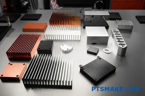
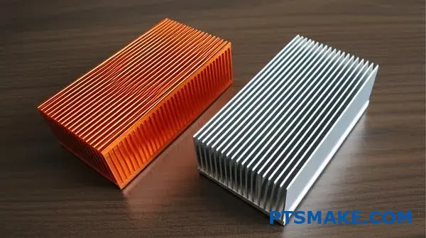
Copper: The Go-To Upgrade
Copper is the most common step up from aluminum. Its thermal conductivity is almost double that of 6061 aluminum, making it fantastic for a powerful heat sink.
The trade-offs are significant weight gain and higher costs. In past projects at PTSMAKE, we typically reserve pure copper for base plates or heat spreaders that directly contact a high-power chip. This hybrid approach balances performance and cost.
Exotic Materials for Peak Performance
When cost is secondary to performance, we turn to more advanced options.
Graphite
Annealed pyrolytic graphite is a game-changer. It is incredibly lightweight and offers directional thermal conductivity up to four times better than copper along its primary plane. This makes it perfect for aerospace or premium portable devices.
Composites and Diamond
For the most challenging designs, we might use Metal Matrix Composites4. These materials combine metals with ceramics to achieve specific properties, such as a low coefficient of thermal expansion. Diamond remains the ultimate thermal conductor, but its cost limits it to highly specialized applications like advanced semiconductors or high-power optics.
| Material | Thermal Conductivity (W/mK) | Key Consideration |
|---|---|---|
| Aluminum (6061) | ~170 | All-Rounder |
| Copper (C110) | ~390 | Heavy, High Performance |
| Graphite (APG) | ~1500 (In-Plane) | Lightweight, Directional |
| Diamond | ~2200 | Extreme Cost & Performance |
Material selection is a critical balancing act. While aluminum is a reliable default, knowing these advanced options exist is crucial for tackling the toughest thermal management problems. The right material choice ensures your device operates reliably under demanding conditions.
When is copper a better choice than aluminum?
The decision often comes down to one key factor: heat. Copper is the clear winner when you need to move heat away from a source quickly.
This is especially true for small, powerful components. Think of high-performance electronics. They generate intense heat in a tiny area.
The Role of Thermal Conductivity
Copper’s ability to conduct heat is nearly double that of aluminum. This makes a huge difference in specific applications. Aluminum can’t always keep up.
| Material | Thermal Conductivity (W/mK) |
|---|---|
| Copper (C110) | ~391 |
| Aluminum (6061) | ~167 |
High-Power-Density Scenarios
When dealing with high-power sources, rapid heat spreading from the base of a heat sink is vital. This prevents hotspots from forming and damaging the component.
Analyzing High-Heat Applications
Let’s look deeper into why copper is essential for certain designs. The goal is to pull thermal energy away from the source as fast as possible. This initial transfer is often the biggest bottleneck in the entire thermal system.
This is where copper’s superior conductivity shines. It acts like a thermal superhighway. It quickly spreads the heat over a larger area. This makes the next step, convection into the air, much more effective.
In our work at PTSMAKE, we often see this with advanced processors and laser systems. The heat is too concentrated for an aluminum heat sink to manage effectively. The material simply can’t move the heat away from the chip fast enough, leading to thermal throttling or failure. Using copper for the base of the heat sink directly addresses this critical issue.
This principle of uniform heat distribution is key. Effective isotropic heat spreading5 is what prevents localized overheating.
Scenarios Favoring Copper
Here are some specific examples where copper is the superior choice for your heat sink design.
| Application | Why Copper is Better |
|---|---|
| High-End CPU/GPU | Prevents thermal throttling under heavy load. |
| High-Power LEDs | Maintains color consistency and extends lifespan. |
| Laser Diodes | Ensures stable operation and prevents wavelength drift. |
| Power Electronics | Manages heat in compact and powerful modules. |
In these cases, the extra cost of copper is a necessary investment. It ensures the reliability and performance of the final product.
Copper’s high thermal conductivity is its main advantage. It excels in applications with small, high-power-density sources where rapidly spreading heat is more critical than the final stage of convective cooling. This makes it essential for high-performance electronics and systems.
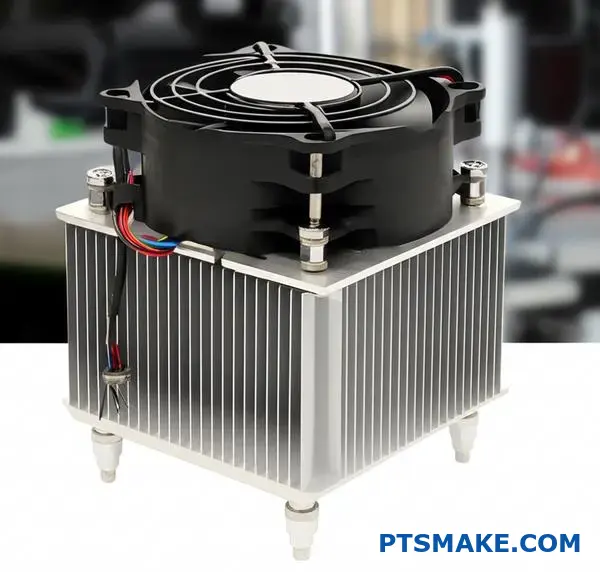
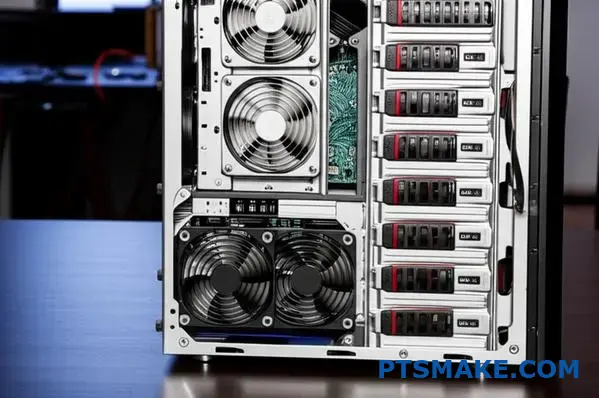
What types of active cooling systems are available?
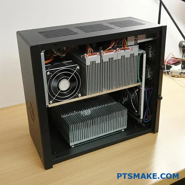
Active cooling is more than just fans. It is about actively moving a fluid, like air or liquid, to transfer heat. This is vital for high-performance electronics.
Solutions range from simple fans to complex liquid systems.
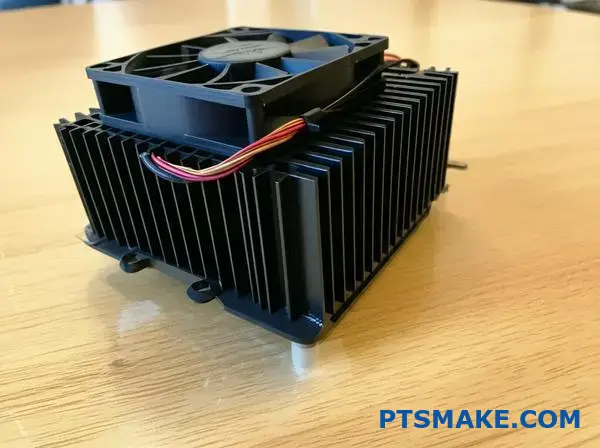
Fan-Based Cooling Solutions
Fans are the most common method. They push air across a heat sink to improve heat transfer. There are two primary types to consider for your design.
| Fan Type | Airflow Characteristic | Ideal Use Case |
|---|---|---|
| Axial Fan | High volume, low pressure | General case ventilation |
| Blower Fan | Low volume, high pressure | Restricted, tight spaces |
Choosing the right fan directly impacts thermal performance.
Parts2:
Parts3:
For more demanding thermal challenges, we must look beyond basic fans.
Advanced Two-Phase Cooling
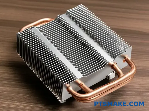
Heat pipe assemblies and vapor chambers are highly efficient. They use a liquid-vapor phase change to move heat quickly.
Vapor chambers are essentially flattened heat pipes. They excel at spreading heat from a small source, like a CPU die, across a larger surface. This prepares the heat for dissipation by a heat sink.
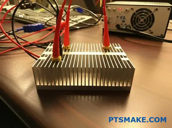
High-Performance Liquid Cooling
For maximum heat removal, liquid cooling is the answer. These closed-loop systems use a pump to circulate a coolant. The liquid absorbs heat from a cold plate on the component. A radiator then releases that heat into the air.
Solid-State Thermoelectric Cooling
Thermoelectric coolers (TECs) are unique. They use the Peltier effect6 to create a temperature difference when a current is applied. One side gets cold while the other gets hot. This technology can cool components below the surrounding ambient temperature. In our projects at PTSMAKE, we integrate these for specialized applications in medical and scientific devices where precision is everything.
| System Type | Key Benefit | Typical Industry |
|---|---|---|
| Heat Pipe Assembly | Versatile heat transport | Consumer Electronics |
| Vapor Chamber | Superior heat spreading | High-Performance Computing |
| Liquid Cooling Loop | Maximum cooling capacity | Data Centers, Automotive |
| Thermoelectric Cooler | Sub-ambient cooling | Medical, Aerospace |
Active cooling includes diverse technologies, from standard fans to advanced vapor chambers and liquid loops. Each solution offers specific advantages, with thermoelectric coolers providing unique sub-ambient performance for highly specialized applications, often paired with a custom heat sink.
Parts5:
What are the common fin geometries and why?
Choosing the right fin geometry is crucial for effective thermal management. The shape directly influences how air interacts with the heat sink. Different designs are engineered for specific airflow conditions.
Understanding these types ensures optimal performance. We’ll explore the three most common geometries. Each serves a unique purpose in heat dissipation.
Straight Fins
These are ideal for forced convection. A fan pushes air in one direction along the fins. They are simple and effective.
Pin Fins
Pin fins are excellent for natural convection. They also work well with low-speed or multidirectional airflow. Their design maximizes surface area exposure.
Flared Fins
Flared fins reduce air resistance. This lowers pressure drop, allowing fans to work more efficiently. This design improves overall system performance.
| Fin Type | Optimal Airflow | Key Advantage |
|---|---|---|
| Straight | Ducted / Forced | Low pressure drop, high efficiency |
| Pin | Omnidirectional | Maximum surface area |
| Flared | Forced | Reduced air resistance |
The geometry of a heat sink fin is not an arbitrary design choice. It is a calculated decision based on the principles of fluid dynamics and heat transfer. Each shape is engineered to manipulate airflow for maximum cooling.
How Geometry Channels Air
Straight fins are the most common for a reason. They create clear channels for ducted airflow, like from a fan. This design ensures that the air moves smoothly across the surface. This creates an efficient heat exchange process.
Pin fins, on the other hand, create more air turbulence. While this might seem less efficient, it’s perfect for omnidirectional or low-velocity airflow. The pins disrupt the thermal boundary layer from any angle, improving heat transfer in unpredictable environments.
Flared fins offer a clever compromise. By increasing the fin gap at the top, they lower the air resistance. This allows a fan to push more air through the heat sink with less effort. In our tests, this often leads to better performance without needing a more powerful fan. This design guides air in a smooth, predictable path, often creating laminar flow7 which is very efficient for heat transfer.
| Geometry | Airflow Interaction | Common Application |
|---|---|---|
| Straight | Creates parallel channels for air | CPU coolers with a dedicated fan |
| Pin | Induces turbulence from multiple directions | LED lighting, natural convection systems |
| Flared | Reduces backpressure for smoother exit | High-density server racks |
Choosing the right fin geometry is a critical engineering decision. It directly impacts thermal performance by controlling how air moves through the heat sink. Straight, pin, and flared fins each serve a specific purpose, ensuring your device stays cool under its intended operating conditions.
How do applications dictate heat sink design categories?
A heat sink is not a one-size-fits-all solution. Its design is entirely dictated by the application’s unique thermal challenges.
A cooler for a gaming CPU is vastly different from one for an industrial LED light. Each has its own priorities.
Key Design Drivers by Application
Understanding these core drivers is the first step in effective thermal design. The requirements are often conflicting.
For example, a quiet CPU cooler needs a different approach than a rugged one for power electronics.
| Application | Primary Design Driver | Secondary Concern |
|---|---|---|
| CPU Cooling | High Power Density | Low Noise |
| LED Lighting | Longevity | Aesthetics |
| Power Electronics | High Temperature | Ruggedness |
This table shows how different end-uses create unique engineering problems. We must solve for the primary driver first.
CPU Cooling: The Battle Against Heat Density
Modern CPUs concentrate immense heat into a tiny area. This high Power density8 is the central challenge. The goal is to move heat away from the chip as quickly as possible.
This often requires complex assemblies. We see heat pipes, vapor chambers, and densely packed fins. Active cooling with fans is standard.
However, for consumer products, noise is a major factor. This creates a difficult balancing act between performance and acoustics.
At PTSMAKE, we often CNC machine custom cold plates and complex fin structures for high-performance computing, where every degree matters.
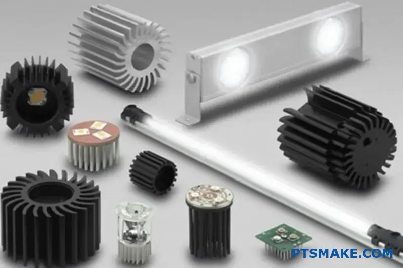
LED Lighting: The Marathon of Longevity
For LEDs, the enemy isn’t peak temperature but sustained heat over time. Heat degrades the LED phosphors, reducing brightness and causing color shifts.
The primary goal is longevity. Most LED heat sinks are passive to improve reliability. They rely on natural convection and radiation.
This means maximizing surface area is crucial. We often see extruded aluminum heat sinks with intricate fin designs that also serve as the light fixture’s housing, blending performance with aesthetics.
Power Electronics: The Demand for Ruggedness
Power converters and inverters operate at very high temperatures. They are often in harsh industrial or automotive environments.
Here, ruggedness and reliability are non-negotiable. The heat sink must withstand vibration, physical shock, and extreme thermal cycling without failure.
Designs are typically robust, using extrusion, forging, or die-casting. The focus is on durable construction over lightweight or intricate designs.
Understanding the application’s primary need—be it performance, longevity, or ruggedness—is crucial. This core requirement shapes every subsequent decision in the heat sink design, material selection, and manufacturing process, ensuring the final product is fit for its specific purpose.
What are the tradeoffs between air and liquid cooling?
Choosing the right cooling system is a critical design decision. It’s not just about raw performance. It involves balancing several practical factors.
To simplify this choice, let’s create a decision matrix. This helps you compare options clearly. We’ll start with the basics.
Key Comparison Factors
Consider how each system meets your project’s specific needs. Is budget the top priority, or is it pure cooling power?
Here’s a quick look at two initial factors.
| Factor | Air Cooling | Liquid Cooling |
|---|---|---|
| Performance | Good to Excellent | Excellent to Extreme |
| Complexity | Low | High |
This table shows the fundamental tradeoff. Liquid cooling offers superior performance. But it comes with increased complexity.
Now, let’s expand our decision matrix. This will give a more complete picture. We need to include cost, size, and maintenance. These factors often determine a project’s real-world viability.
Expanded Decision Matrix
At PTSMAKE, we guide clients through this analysis for their custom parts. We look at the entire product lifecycle. This prevents costly changes later.
A robust cooling solution must be effective and practical. For instance, the thermal resistance9 of a liquid system is typically lower. This means it transfers heat more efficiently away from the source. However, this benefit comes at a price.
This expanded table covers the key tradeoffs we discuss with clients.
| Factor | Air Cooling (Heatsink & Fan) | Liquid Cooling (AIO/Custom) |
|---|---|---|
| Thermal Performance | Limited by ambient air temperature and heat sink size. | Superior heat dissipation capacity; ideal for overclocking. |
| System Complexity | Simple installation; fewer components. | More complex; involves pumps, radiators, tubing, and fluid. |
| Cost | Generally lower initial investment. | Higher initial cost, especially for custom loops. |
| Size/Volume | Requires significant clearance around the CPU. | More flexible placement, but radiator needs space. |
| Reliability | Very reliable; fan is the only moving part. | Potential for leaks or pump failure; requires more checks. |
This matrix clarifies the decision. For most applications, air cooling is simple and cost-effective. But for high-power systems needing maximum cooling, liquid is the clear winner.
Choosing between air and liquid cooling requires a clear-eyed look at project priorities. Our decision matrix highlights the key tradeoffs in performance, complexity, cost, size, and reliability, helping you select the optimal solution for your specific application.
What is the step-by-step process for selecting a heat sink?
Selecting the right heat sink isn’t guesswork. It’s a structured process. Following a clear workflow ensures your components stay cool and reliable.
This practical guide breaks it down. We’ll start with the essential thermal data you need.
Then, we will move through calculations and physical constraints. This systematic approach eliminates errors and saves time.
Define Your Thermal Needs
First, you must gather three key thermal parameters. These form the foundation of your selection process. Without them, you’re flying blind.
| Parameter | Description |
|---|---|
| TDP (Thermal Design Power) | The maximum heat a component generates in watts. |
| Tmax (Max Junction Temp.) | The highest operating temperature for the component. |
| Tambient (Ambient Temp.) | The maximum temperature of the air surrounding the heat sink. |
The Practical Selection Workflow
A logical workflow prevents costly mistakes. It moves from thermal theory to physical reality. This ensures the final heat sink fits and performs correctly.
Calculate Thermal Resistance
The most critical calculation is for thermal resistance (Rθ). This value tells you how efficiently the heat sink must dissipate heat.
The formula is: Rθ = (Tmax – Tambient) / TDP.
A lower Rθ value means better performance. This calculation must also account for thermal interface material and Spreading Resistance10. These factors can impact the final result.
Mechanical and Cooling Constraints
Next, consider the physical space. A great heat sink is useless if it doesn’t fit.
| Constraint | Key Considerations |
|---|---|
| Size (mm) | Length, width, and height limitations in your enclosure. |
| Weight (g) | Can the PCB support the weight? Is shock/vibration a concern? |
| Mounting | How will it attach? Push pins, screws, or adhesive? |
Finally, decide between passive and active cooling.
Passive vs. Active Cooling
| Cooling Type | Best For | Considerations |
|---|---|---|
| Passive | Low-power applications, silent operation. | Requires good natural airflow. Larger size for same performance. |
| Active (Fan) | High-power applications, compact spaces. | Adds noise, power consumption, and a point of failure. |
Once you have these specs, you can filter manufacturer catalogs. Always verify your choice with their performance curves to ensure it works under your specific airflow conditions.
This structured workflow—define, calculate, constrain, select, and verify—is the key to choosing the correct heat sink. It turns a complex task into a series of manageable steps, ensuring optimal thermal performance and mechanical compatibility for your design.
How to calculate required heat sink thermal resistance?
Calculating the right heat sink is less about guesswork and more about simple math. The core formula is your best friend here. It helps determine the maximum thermal resistance a heat sink can have while keeping your component cool.
The Core Formula
The fundamental equation you need is:
R_required = (T_case_max - T_ambient_max) / Power - R_interface
Here’s a quick breakdown of each part.
| Variable | Description |
|---|---|
| R_required | The maximum thermal resistance for the heat sink (°C/W). |
| T_case_max | The component’s maximum allowable case temperature (°C). |
| T_ambient_max | The maximum expected ambient temperature (°C). |
| Power | The heat the component dissipates in watts (W). |
| R_interface | The thermal resistance of the interface material (°C/W). |
This formula ensures you select a heat sink that performs effectively under worst-case conditions.
A Practical Calculation Example
Theory is good, but let’s apply this to a real-world scenario. This is a process we often guide our clients at PTSMAKE through to ensure their custom heat sink designs are effective from the start.
Imagine we need to cool a processor.
Setting the Parameters
First, we gather our data. You can find most of this in the component’s datasheet or by defining your system’s operating environment.
| Parameter | Value |
|---|---|
| Max Case Temp (T_case_max) | 85°C |
| Max Ambient Temp (T_ambient_max) | 40°C |
| Power Dissipation (Power) | 25 W |
| Interface Resistance (R_interface) | 0.2 °C/W |
The total heat generated, or power dissipation11, is a critical value. You must account for the actual power your component will convert into heat during operation, not just its total power consumption. This ensures your thermal solution is designed for the real thermal load.
Step-by-Step Calculation
Now, we plug these values into our formula.
Calculate the temperature difference (ΔT):
ΔT = T_case_max - T_ambient_max
ΔT = 85°C - 40°C = 45°CCalculate the total required resistance:
R_total = ΔT / Power
R_total = 45°C / 25 W = 1.8 °C/WSubtract the interface resistance:
R_required = R_total - R_interface
R_required = 1.8 °C/W - 0.2 °C/W = 1.6 °C/W
The result is 1.6 °C/W. You must find a heat sink with a thermal resistance of 1.6 °C/W or lower.
This simple calculation is the foundation of effective thermal management. It moves you from estimation to a precise requirement, ensuring the heat sink you choose will actually do its job and protect your electronics from overheating.
What data is essential for heat sink selection?
To properly select a heat sink, you need a clear checklist. This prevents guesswork and ensures performance. It’s a simple process.
We start with four key data points. These form the foundation for any successful thermal management solution. Getting these right from the start is crucial.
Your Essential Data Checklist
| Data Point | Description |
|---|---|
| TDP | Thermal Design Power (Watts) |
| Tj,max | Max Junction Temperature (°C) |
| Tambient,max | Max Ambient Temperature (°C) |
| Constraints | Physical space available (mm) |
This simple table is our starting point for every project.

A checklist streamlines the entire process. At PTSMAKE, we always begin by confirming these core parameters with our clients. It avoids costly errors and redesigns later. Let’s break down why each one matters.
Thermal Load and Limits
Thermal Design Power (TDP) tells us the maximum heat a component generates. It’s our primary input. But we also need the maximum allowable junction temperature12. This is the critical limit the component cannot exceed without risking damage or failure.
Next, we consider the operating environment. The maximum ambient temperature is vital. A heat sink performs differently in a 25°C room versus a 50°C enclosure. Ignoring this can lead to overheating.
Physical and Mounting Constraints
Finally, we address the physical reality. Space is often a premium. We need the exact dimensions (Length x Width x Height) available for the heat sink. This dictates the maximum possible size.
The mounting pattern is just as important. How will the heat sink attach to the board or component? The hole locations and hardware type must be defined.
| Constraint Type | Key Questions to Answer |
|---|---|
| Spatial | What are the L x W x H limits? Any keep-out zones? |
| Mounting | What is the hole pattern? What type of hardware (screws, clips)? |
| Airflow | Is there a fan? What is the airflow direction and rate? |
These details ensure the proposed solution will actually fit and function within the system.
In summary, selecting a heat sink relies on four pillars: thermal load (TDP), temperature limits (Tj,max), operating environment (Tambient), and physical constraints. Without this complete dataset, any selection is just an estimate. We need precise data for a reliable solution.
How to interpret a heat sink performance datasheet?
The most critical part of any heat sink datasheet is the performance graph. This chart maps thermal resistance against airflow. It’s the key to your decision.
This graph isn’t just data. It tells you exactly how the heat sink will perform inside your product. It helps you match the component to your system’s real-world conditions.
The Core Relationship
This chart visually represents a simple truth. More airflow over a heat sink leads to lower thermal resistance. This means better cooling performance. Understanding this is vital.
Key Performance Indicators
| Parameter | Unit | Description |
|---|---|---|
| Airflow | LFM or CFM | The speed of air moving across the heat sink. |
| Thermal Resistance | °C/W | The heat sink’s opposition to heat flow. Lower is better. |
Using the Thermal Performance Curve
This graph is your primary tool for validation. It helps you confirm if a potential heat sink can handle the thermal load of your component under your system’s specific airflow conditions. Let’s break down how to use it.
Step 1: Determine Your System’s Airflow
First, you must know the airflow your system provides. This is measured where the heat sink will be located. It is typically expressed in Linear Feet per Minute (LFM) or Cubic Feet per Minute (CFM). This value is your starting point on the graph’s horizontal axis (X-axis).
Step 2: Find Thermal Resistance on the Graph
Once you have your airflow value, find it on the X-axis. From that point, draw a line straight up to the performance curve. Then, draw a line horizontally to the left to the vertical axis (Y-axis). This point on the Y-axis is the heat sink’s thermal resistance (°C/W) at your specific airflow. The entire process relies on the principles of Convective Heat Transfer13 to function.
Step 3: Compare and Decide
Now, compare this thermal resistance value from the graph to the required thermal resistance you calculated earlier.
| Scenario | Outcome |
|---|---|
| Datasheet Rth < Required Rth | The heat sink is a suitable candidate. |
| Datasheet Rth > Required Rth | The heat sink will not provide enough cooling. |
If the datasheet value is lower, the heat sink is a good fit. At PTSMAKE, we often guide our partners through this selection process, ensuring the chosen component meets their design specifications precisely.
The Thermal Resistance vs. Airflow graph is essential. It lets you verify if a heat sink will perform adequately in your specific environment. This step is crucial for preventing component overheating and ensuring product reliability.
How is CFD used for heat sink design validation?
Computational Fluid Dynamics (CFD) is a key tool. It acts as a virtual wind tunnel for us. This lets us test a heat sink design digitally.
We can accurately predict airflow patterns. We also see how temperature spreads across the heat sink.
The Virtual Testing Advantage
This digital approach allows for rapid iteration. We can test multiple design ideas quickly without building physical parts. It saves time and lowers development costs significantly.
| Aspect | CFD Simulation (Virtual) | Physical Prototype |
|---|---|---|
| Cost | Lower | Higher |
| Speed | Fast | Slow |
| Data | Comprehensive | Limited |
| Flexibility | High | Low |
This process ensures the first physical prototype is much closer to the final design.
Deeper Insights from Simulation
CFD goes beyond simple airflow visualization. It numerically solves the fundamental equations of fluid motion. This provides incredibly detailed data on the thermal performance of a heat sink.
At its core, the software tackles the complex Navier-Stokes equations14 that govern fluid flow. This allows us to see things invisible to the naked eye. We can identify recirculation zones where air gets trapped. Or find velocity dead spots where cooling is ineffective.
Optimizing Before Manufacturing
By analyzing this data, we can make informed design changes. We might adjust fin spacing, height, or the overall shape of the heat sink to improve performance. At PTSMAKE, we often run these simulations for our clients’ designs.
This pre-production analysis helps us provide valuable feedback. It ensures the part we machine will meet their thermal requirements from the start.
| Parameter Analyzed | Impact on Heat Sink Design |
|---|---|
| Air Velocity | Determines convective cooling efficiency. |
| Pressure Drop | Affects fan selection and system airflow. |
| Temperature Maps | Pinpoints hot spots on the device and sink. |
| Flow Trajectories | Visualizes air paths and identifies blockages. |
This detailed analysis prevents costly and time-consuming physical redesigns. It’s about getting it right the first time.
CFD simulation provides a digital environment to test and validate heat sink designs. It uses advanced physics to predict airflow and temperature, allowing for crucial design optimization before any metal is cut. This proactive approach saves time, reduces costs, and ensures better performance.
What are best practices for applying TIM?
Applying Thermal Interface Material (TIM) correctly is critical. It’s not just about spreading paste. It’s a precise process that ensures optimal heat transfer.
Proper application starts with a clean surface. It ends with the right mounting pressure. Every step impacts the final performance of your heat sink assembly. Let’s break down the best practices.
Key Application Factors
| Factor | Consequence of Error | Best Practice |
|---|---|---|
| Surface Prep | Trapped contaminants | Use Isopropyl Alcohol (IPA) |
| Amount | Air gaps or overflow | Aim for a thin, even layer |
| Pressure | Poor contact | Follow component specifications |
Application Patterns
Choosing the right pattern depends on the chip size. A single dot works for small CPUs. Larger surfaces may need a line or an X pattern to ensure full coverage without trapping air.
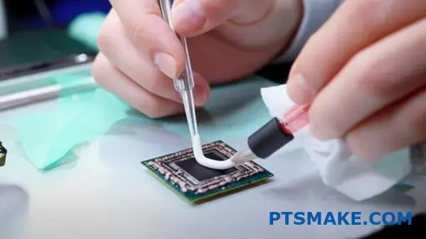
Step 1: Surface Preparation is Non-Negotiable
Before anything else, both the component and the heat sink surfaces must be perfectly clean. We use lint-free cloths and a high-purity isopropyl alcohol (IPA) solution. Even a fingerprint can introduce oils that impede thermal transfer. Any residue from previous applications must be completely removed. This first step is the foundation for a successful thermal bond.
Step 2: The "Just Right" Amount
A common mistake is thinking more TIM is better. Too much material increases the bond line thickness (BLT). This actually raises thermal resistance. Conversely, too little material leads to air gaps, which are terrible insulators. The goal is a minimal, uniform layer that fills only the microscopic imperfections between the two surfaces. Achieving this minimizes interfacial resistance15 and maximizes heat flow.
Step 3: Application Pattern and Pressure
The application pattern helps distribute the TIM evenly when pressure is applied. Here’s a quick guide we use at PTSMAKE when advising clients.
| Pattern | Best For | Pro | Con |
|---|---|---|---|
| Single Dot | Small, square CPUs | Simple, low air bubble risk | Uneven on large surfaces |
| Line / X-Pattern | Rectangular or large CPUs | Better coverage | Higher risk of trapping air |
| Spread | All types (manual) | Guarantees full coverage | Can easily trap air if done poorly |
After applying the TIM, mounting the heat sink with even pressure is the final piece. This pressure squeezes out excess material and ensures the thinnest possible bond line. Always follow the torque specifications for the mounting hardware.
Proper TIM application is a science. It demands clean surfaces, the precise amount of material, a suitable pattern, and correct mounting pressure. Mastering these steps ensures your components remain cool and reliable under load.
How to design for airflow in an enclosure?
System-level design is crucial. Think of your enclosure as a city. You need to design a superhighway for air to travel smoothly.
This means creating a clear, direct path. Air should flow from the cool inlet, across the hot components, and out the exhaust.
The Path of Least Resistance
Your goal is to make this path as easy as possible. Any obstacle creates a traffic jam, reducing cooling efficiency. Even small things matter.
Key Considerations
| Good Practice | Bad Practice |
|---|---|
| Clear, direct path | Many bends and turns |
| Organized cables | Messy, tangled cables |
| Aligned heat sink | Fins blocking airflow |
| Minimal obstructions | Components in the way |
Proper system design ensures every component, especially the heat sink, works at its best.
Creating a Clear Airflow Path
The most effective cooling strategy starts with a defined path. Air needs a straight line from the inlet fan to the exhaust. Don’t let it wander.
This ensures the cool air directly targets the hottest components. Any deviation or recirculation reduces the system’s ability to dissipate heat effectively.
Minimizing Obstructions
Every component in the airflow path creates resistance. Tall capacitors, brackets, or poorly placed PCBs can disrupt flow, creating hot spots.
This resistance is often called impedance16. Lowering it is key. We often advise clients at PTSMAKE to consider component layout early in the design phase. A small change can have a big impact.
Cable Management is Not Just for Looks
Loose, messy cables are a primary source of obstruction. They can block a significant portion of the airflow path, drastically reducing cooling.
| Technique | Benefit |
|---|---|
| Zip ties or bundling | Creates clean channels for air. |
| Custom-length cables | Eliminates excess slack. |
| Routing along walls | Keeps the central path clear. |
Aligning the Heat Sink
This is a critical detail. The fins of the heat sink must be aligned with the direction of airflow.
If fins are perpendicular to the flow, they act like a wall. This blocks air and prevents the heat sink from working properly. Parallel alignment lets air move freely between the fins, carrying heat away efficiently.
A well-designed enclosure treats airflow as a priority. It ensures a clear path from inlet to outlet, manages cables, minimizes obstructions, and aligns the heat sink correctly for optimal thermal performance.
How to prototype and test a thermal solution?
Experimental validation is where theory meets reality. It is the crucial step to confirm if your thermal solution, such as a custom heat sink, performs as designed. This process moves beyond simulation.
We create a real-world test to get hard data. This ensures the component will be reliable.
Key Validation Steps
The process is methodical. We must control variables to get accurate results. The goal is to measure the actual thermal performance under a known heat load. This confirms our design choices.
| Equipment | Purpose |
|---|---|
| Thermocouples | Precisely measure temperature at key points. |
| Power Supply | Apply a controlled, known heat load. |
| Thermal Chamber | Create a stable ambient temperature. |
| Data Logger | Record temperature data over time. |
This physical testing provides undeniable proof of performance.
The Experimental Process in Detail
Validating a thermal solution requires precision. In past projects at PTSMAKE, we’ve found that careful setup is everything. It prevents misleading data that could lead to field failures later on. The entire process hinges on accuracy and control.
Instrumenting the Heat Source
First, we attach thermocouples directly to the heat source. We also place them on the heat sink and at key points in the surrounding air. Placement is critical for capturing an accurate thermal profile of the system. This shows us how heat moves.
Creating a Controlled Environment
Next, we place the entire assembly inside a thermal chamber. This allows us to set and maintain a specific ambient temperature. It removes external environmental fluctuations from the equation. This ensures our test results are repeatable and reliable.
Achieving a steady-state condition17 is the main goal here. This means temperatures have stabilized and are no longer changing over time. We apply a known, constant heat load to the component. Then, we wait until all thermocouple readings are stable. Only then do we record the final performance data.
| Parameter | Expected (Simulation) | Actual (Test) |
|---|---|---|
| Max Component Temp | 85°C | 83°C |
| Heat Sink Temp | 65°C | 64°C |
| Ambient Temp | 25°C | 25°C |
Experimental validation bridges the gap between design simulation and real-world performance. It involves precise instrumentation, a controlled environment, and methodical data collection to confirm that your thermal solution meets the required specifications. This step is non-negotiable for ensuring product reliability.
How does pressure drop affect fan and heat sink selection?
Choosing the right fan involves more than just its maximum airflow rating. You must match the fan to your system’s resistance.
This is a balancing act. It is defined by two critical graphs: the fan performance curve and the system impedance curve.
The Key Players
Fan Performance Curve
This curve, from the fan’s manufacturer, shows how much air the fan can move against different levels of pressure.
System Impedance Curve
This curve represents the resistance of your entire system. This includes the chassis, filters, and especially the heat sink.
| Characteristic | Fan Performance Curve | System Impedance Curve |
|---|---|---|
| What it Shows | The fan’s strength | The system’s resistance |
| Source | Provided by fan maker | Determined by your design |
| Goal | To overcome resistance | To be minimized for flow |
The real performance of your cooling system is found where these two curves intersect. This intersection is called the operating point.
It shows the actual airflow and static pressure you will get in your specific device. You cannot look at the fan curve alone.
Finding the Operating Point
The goal is to find this "sweet spot". The system impedance18 is not linear. As airflow tries to increase, the resistance from components like a dense heat sink grows much faster.
In our past projects at PTSMAKE, we’ve seen how a poorly matched fan and heat sink lead to problems. A fan might be rated for 50 CFM in open air but only deliver 20 CFM in a high-resistance system.
This mismatch results in poor cooling or excessive noise. We always analyze these curves to ensure components work together effectively.
The table below shows how pressure drop can increase with airflow in a typical system.
| Airflow (CFM) | Required Pressure (inH2O) |
|---|---|
| 10 | 0.02 |
| 20 | 0.08 |
| 30 | 0.18 |
| 40 | 0.32 |
This illustrates the challenge. Doubling the airflow can quadruple the required pressure from the fan. A well-designed heat sink is crucial.
The operating point is where the fan’s capability meets the system’s resistance. Finding this intersection on the graph is essential for predicting the actual airflow and ensuring your components are properly cooled without creating unnecessary noise or wasting power.
How to balance performance, cost, and size constraints?
This is the core challenge in engineering. Every project forces a trade-off between performance, cost, and size. You can’t maximize all three.
Your primary goal dictates the best path. Is budget the main concern? Or is a compact design non-negotiable? Maybe peak performance is the only thing that matters.
Understanding your project’s priority is the first step. This balance defines the final product’s success. It guides every material and design choice.
| Constraint | Primary Focus |
|---|---|
| Performance | Maximum cooling efficiency |
| Cost | Lowest production expense |
| Size | Smallest physical footprint |
Let’s explore this with real-world scenarios. Each path leads to a very different solution for your heat sink design. Your project’s driver is the key.
Scenario 1: Cost is the Driver
If the budget is tight, extruded aluminum heat sinks are often the answer. They are mass-produced and cost-effective. The tooling is relatively inexpensive.
While not the highest performing, they are perfect for many consumer electronics. They offer good cooling for their price.
Scenario 2: Space is Tight
For compact devices like laptops or handhelds, space is a luxury. Here, a heat pipe becomes necessary. It doesn’t dissipate much heat on its own.
Instead, it efficiently moves heat from a small source to a larger fin stack. This allows for flexible and compact designs.
Scenario 3: Performance is Paramount
When you need maximum cooling, cost and size become secondary. Think of high-end gaming PCs or servers. Liquid cooling is often the only choice.
It’s complex and expensive. But it removes heat far more effectively than air cooling. Lowering Thermal resistance19 is the main goal here. At PTSMAKE, we machine the complex cold plates required for these systems.
| Scenario Driver | Typical Solution | Key Benefit |
|---|---|---|
| Cost | Extruded Heat Sink | Low unit price |
| Size | Heat Pipe Assembly | Design flexibility |
| Performance | Liquid Cooling | Superior heat dissipation |
Choosing a thermal solution is a balancing act. Your project’s main driver—cost, size, or performance—will point to the right choice, whether it’s a simple extrusion, a heat pipe, or a complex liquid cooling system.
How to balance cooling performance and acoustic noise?
A powerful device is useless if it’s too loud. Noise is a critical user experience constraint. The goal is to remove heat efficiently without creating a racket.
Finding the Sweet Spot
Achieving this balance is a core challenge in product design. It requires a thoughtful approach to thermal management components.
Key Methods for Noise Reduction
We can tackle this problem from three angles. These include fan selection, intelligent control, and heat sink design. Each plays a vital role.
| Method | Primary Goal | Impact on Noise |
|---|---|---|
| Larger, Slower Fans | Move more air quietly | Significant Reduction |
| PWM Fan Control | Match speed to load | Dynamic Reduction |
| Low-Resistance Heat Sink | Ease airflow | Moderate Reduction |
This combination allows for effective and quiet cooling.
The Physics of Quiet Cooling
Using larger fans is a simple yet effective strategy. A 120mm fan spinning at 1000 RPM can move more air than an 80mm fan at 1500 RPM, but with far less noise. The slower rotation reduces mechanical and air turbulence sounds.
Intelligent Fan Speed Management
Modern systems don’t need full cooling power all the time. This is where smart controls come in. By implementing Pulse-Width Modulation20 (PWM), fan speed adjusts dynamically based on the actual thermal load. The fan only spins as fast as necessary. This prevents the constant drone of a fan running at maximum speed during idle or low-load situations.
Aerodynamics in Heat Sink Design
The design of the heat sink itself is crucial. A component with high aerodynamic resistance forces the fan to work harder, generating more noise to push air through.
Fin Spacing and Airflow
In past projects at PTSMAKE, we’ve focused on optimizing fin spacing. A well-designed heat sink allows air to pass through with minimal obstruction. This lowers the required fan pressure and, consequently, the noise level.
| Thermal Load | Required Fan Speed | Resulting Noise Level |
|---|---|---|
| Idle (10%) | 20% (800 RPM) | Very Low |
| Medium (50%) | 50% (1500 RPM) | Moderate |
| High (100%) | 100% (3000 RPM) | High |
Balancing performance and acoustics is not about compromise. It’s about intelligent engineering. By combining larger, slower fans with PWM control and low-resistance heat sinks, we create systems that are both powerful and pleasantly quiet, enhancing the overall user experience.
Analyze a failed cooling design: what went wrong?
Let’s dive into a common problem. A client’s new server kept overheating. It had what looked like a solid design, but it failed under load.
Why did this happen?
We will perform a root cause analysis together. This process helps us find the exact failure point. It is a systematic way to solve complex thermal issues.
The Thermal Chain
We will break down the entire thermal chain step by step. This allows us to inspect each link for potential failure.
In this server case, the thermal chain has several key links. We must check each one for weakness. The investigation starts at the heat source and moves outward.
Step 1: The Heat Source (CPU)
First, we verified the CPU’s power draw. Was it operating within its Thermal Design Power (TDP)? Sometimes, firmware issues can cause excessive heat. The client confirmed stock settings, so we moved on.
Step 2: The Thermal Pathway
Next, we looked at the interface and the heat sink. The Thermal Interface Material (TIM) is critical. Was it applied correctly? Too much or too little is a common failure point. The high heat flux21 from modern CPUs demands an efficient path.
Step 3: Airflow and Environment
Finally, we checked airflow. Were the fans spinning correctly? Was the chassis intake or exhaust blocked? In our tests, everything seemed fine here.
Our root cause analysis checklist quickly revealed the problem:
| Component | Check Point | Status |
|---|---|---|
| CPU | TDP Compliance | Pass |
| TIM | Application Quality | Fail |
| Heat Sink | Design Efficacy | Pass |
| Airflow | Fan RPM & Path | Pass |
In projects we’ve handled at PTSMAKE, a simple assembly error is often the culprit. The TIM was unevenly applied, creating insulating air gaps. This small mistake broke the entire cooling system.
This case study shows that a cooling failure is often a small detail, like poor TIM application. A systematic analysis of the entire thermal chain is the only way to find and fix the true root cause of the problem.
Design a thermal solution for a high-power LED.
Let’s put theory into practice with a real-world design challenge. We need to cool a high-power 150W Chip-on-Board (COB) LED.
The critical constraint is that the solution must be entirely passive. This means no fans. Our primary goal is to keep the LED’s junction temperature from exceeding 125°C.
Design Specifications
Here are the key parameters we’ll be working with. These are typical for high-bay lighting or industrial applications.
| Parameter | Value |
|---|---|
| LED Power (P) | 150 W |
| Max Junction Temp (T_j) | 125 °C |
| Cooling Method | Passive (Natural Convection) |
| Assumed Ambient Temp (T_a) | 25 °C |
This scenario requires a robust and well-designed heat sink.
Step 1: Calculating Required Thermal Resistance
First, we must determine the maximum total thermal resistance the system can have. This is the path from the LED junction to the ambient air.
The formula is straightforward:
R_total = (T_j – T_a) / P
Plugging in our values:
R_total = (125°C – 25°C) / 150W
R_total = 0.67 °C/W
This 0.67 °C/W is our total thermal budget. Anything higher, and the LED will overheat.
Step 2: Breaking Down the Resistance Path
The total resistance is a sum of several parts. It includes the LED’s internal resistance, the Thermal Interface Material22, and the heat sink itself.
R_total = R_jc + R_cs + R_sa
We need to find the required performance of our heat sink (R_sa). To do this, we use typical values for the other components.
| Resistance Component | Description | Typical Value (°C/W) |
|---|---|---|
| R_jc | Junction-to-Case (from LED datasheet) | 0.10 |
| R_cs | Case-to-Sink (TIM) | 0.05 |
| R_sa | Sink-to-Ambient (Our Target) | ? |
Now, we solve for R_sa:
R_sa = R_total – R_jc – R_cs
R_sa = 0.67 – 0.10 – 0.05
R_sa = 0.52 °C/W
This result is our design target. We must select or custom-design a passive heat sink with a thermal resistance of 0.52 °C/W or less.
We’ve defined our challenge for a 150W LED. The key takeaway is the calculated target: our passive heat sink must have a thermal resistance of 0.52 °C/W or lower. This specific metric now drives all our subsequent design and manufacturing decisions at PTSMAKE.
What are the latest innovations in heat sink technology?
The world of thermal management is evolving quickly. We are moving past simple extruded aluminum fins. New technologies are changing how we cool electronics.
This shift is driven by smaller, more powerful devices. They generate incredible heat in tight spaces.
Pushing the Boundaries of Cooling
Innovations focus on three main areas. These are advanced manufacturing, new materials, and smarter designs. Each offers a unique way to improve heat dissipation.
Key Areas of Innovation
3D printing allows for complex, organic shapes. These were impossible to make before.
Microchannel heat sinks use tiny fluid passages. They offer superior performance for liquid cooling applications.
The table below shows a quick comparison.
| Feature | Traditional Heat Sink | Innovative Heat Sink |
|---|---|---|
| Manufacturing | Extrusion, CNC Machining | 3D Printing, Advanced Bonding |
| Design | Simple Fins, Standard Shapes | Complex Geometries, Optimized |
| Material | Aluminum, Copper | Composites, Phase-Change |
| Cooling Method | Passive Air Cooling | Liquid Cooling, Two-Phase |
Exploring these innovations helps us find the best cooling solutions. At PTSMAKE, we often advise clients on which technology fits their specific needs. It’s not about what’s newest, but what’s most effective for the application.
A Closer Look at Emerging Solutions
Let’s break down these cutting-edge technologies. Each one solves a different thermal challenge, pushing the limits of what’s possible for a modern heat sink.
3D Printing and Topology Optimization
Additive manufacturing, or 3D printing, is a game-changer. It lets us create heat sinks with optimized topologies. These are lightweight, intricate structures designed by software to maximize surface area and airflow.
In our past projects, we’ve seen 3D printed prototypes outperform traditionally machined parts by a significant margin. This is especially true in applications with unusual space constraints.
Advanced Vapor Chambers and Materials
Vapor chambers are a more advanced form of heat pipe. They spread heat very quickly and evenly across a large surface. This makes them ideal for high-power processors.
New composite thermal materials are also emerging. These materials can be engineered to have unique properties, such as anisotropic thermal conductivity23. This means they can direct heat along a specific path, away from sensitive components.
| Technology | Best Use Case | Key Advantage |
|---|---|---|
| Microchannel | High-density electronics | Superior liquid cooling efficiency |
| 3D Printed | Custom, complex applications | Unmatched design freedom |
| Vapor Chamber | High-power CPUs/GPUs | Excellent heat spreading |
| Composites | Specialized thermal paths | Tunable thermal properties |
Emerging technologies like 3D printing, advanced vapor chambers, and novel composite materials are redefining heat sink capabilities. They offer custom, high-performance solutions far beyond traditional methods, enabling better cooling for next-generation electronics.
Transform Your Heat Sink Projects with PTSMAKE
Ready to elevate your heat sink design or need expert manufacturing solutions? Contact PTSMAKE now for a fast, no-obligation quote! Our team delivers precision, reliability, and rapid turnaround on CNC-machined and injection-molded heat sink components—trusted by industry leaders worldwide. Start your inquiry today!

Discover how this crucial property is measured and why it is the key to effective thermal management. ↩
Learn how this material property is critical for effective heat dissipation. ↩
Explore how the choice of this material can enhance thermal conductivity and product reliability. ↩
Explore how these advanced materials combine metal and ceramic properties for superior performance in extreme environments. ↩
Understand the physics of uniform heat transfer and its impact on thermal management. ↩
Learn how this effect uses electricity to create a temperature difference for active cooling. ↩
Learn how smooth, non-turbulent airflow dramatically improves thermal efficiency in heat sink design. ↩
Learn how this key metric directly impacts thermal management strategy and design choices. ↩
Learn how this key property impacts the efficiency of your cooling solution and overall system performance. ↩
Understand this key factor to improve your thermal calculation accuracy. ↩
Understand how power converts to heat and impacts your thermal design. ↩
Learn why this internal chip temperature is the most critical metric for ensuring device reliability. ↩
Learn more about the principles of how airflow dissipates heat from a surface. ↩
Discover the fundamental equations governing fluid motion that make CFD analysis possible. ↩
Learn how this critical factor directly impacts heat transfer efficiency and component lifespan. ↩
Learn how to calculate and minimize airflow impedance for better thermal design. ↩
Learn why reaching this state is essential for reliable and repeatable thermal performance data. ↩
Learn how to calculate system resistance for precise thermal management. ↩
Learn how this key metric determines a heat sink’s ability to dissipate heat effectively. ↩
Learn how this technique precisely controls fan speed for quieter and more efficient cooling systems. ↩
Learn how this critical metric influences your heat sink design and material choices for optimal performance. ↩
Understand how these materials are critical for bridging microscopic air gaps to maximize heat transfer. ↩
Learn how materials can conduct heat differently in various directions for optimized cooling. ↩