Designing driving gears looks simple on paper, but one miscalculation can turn your precision machinery into a costly failure. Many engineers struggle with the gap between textbook theory and real-world application, leading to premature gear failures, excessive noise, or complete system breakdowns.
A driving gear design guide provides systematic answers to critical questions covering gear fundamentals, material selection, load calculations, manufacturing specifications, and failure prevention. This comprehensive approach ensures reliable gear systems that meet performance requirements while avoiding common design pitfalls.
Through my experience at PTSMAKE, I’ve compiled 22 essential questions that cover everything from basic gear principles to advanced design considerations. This guide bridges the theory-to-practice gap that many engineers face when designing reliable gear systems for demanding applications.
What is the gear’s fundamental purpose beyond transmitting motion?
Most people see gears and think of simple motion transfer. But their true purpose is far more profound. They are fundamental tools for manipulating force and speed.
Gears as Force Multipliers
Gears act like rotating levers. They multiply torque, the rotational equivalent of force. This allows a small motor to move a heavy load with ease. It’s about gaining mechanical advantage.
Controlling Speed with Precision
This torque multiplication comes at a cost: speed. When torque increases, rotational speed decreases proportionally. This trade-off is central to mechanical design.
| Gear Setup | Torque | Speed |
|---|---|---|
| Small to Large | Increases | Decreases |
| Large to Small | Decreases | Increases |
| Same Size | Unchanged | Unchanged |
This control is essential for countless applications.
The Principle of Mechanical Advantage
At its core, a gear system is a clever application of levers. Imagine the teeth of two meshing gears. Each point of contact acts like a fulcrum, allowing force to be multiplied.
The gear ratio, determined by the tooth count of the driving gear versus the driven gear, dictates this advantage. A high ratio means significant torque multiplication. This is a fundamental concept in powertrain design.
Understanding this principle allows us to design systems with incredible power and precision. The interaction happens along the pitch circle1, an imaginary circle where the teeth effectively engage.
Practical Applications in Powertrains
This concept is everywhere. It’s in your car’s transmission, allowing the engine to operate efficiently at various speeds. It’s in industrial machinery, providing the force needed for heavy tasks.
At PTSMAKE, we frequently work with clients to design custom gear systems. We help them select the right materials and gear ratios. This ensures the final assembly meets precise performance specifications, from prototype to production. The proper selection of the driving gear is often the most critical decision in this process.
| Ratio (Driven:Driving) | Torque Change | Speed Change | Example Use Case |
|---|---|---|---|
| 4:1 | 4x Increase | 4x Decrease | Heavy Lifting Winch |
| 1:1 | No Change | No Change | Simple Conveyor |
| 1:4 | 4x Decrease | 4x Increase | High-Speed Fan |
Gears fundamentally alter mechanical power. They don’t just transmit motion; they transform it. This allows for precise control over torque and speed, enabling the function of complex machinery. It’s about leveraging basic physics to achieve powerful results in engineering.
What are pressure angle and its effect on gear performance?
In simple terms, the pressure angle is a key parameter in gear design. It defines the direction of the force between mating gear teeth. Think of it as the angle of attack.
This angle directly influences how a gear performs. The most common pressure angles you’ll encounter are 14.5°, 20°, and 25°. Each offers a distinct set of trade-offs.
Here’s a quick overview of these standard angles.
| Standard Angle | Common Era |
|---|---|
| 14.5° | Older standard |
| 20° | Current industry standard |
| 25° | High-performance applications |
Choosing the right one is crucial for your project’s success. It’s a balance between strength and other performance factors.
Understanding the Trade-Offs
The choice of pressure angle creates a direct trade-off. It’s primarily between tooth strength and the radial force exerted on bearings. This force is transmitted along the line of action2.
A larger pressure angle results in a wider and thicker gear tooth at its base. This geometry makes the tooth stronger and more resistant to bending and breaking under load. It can handle more torque.
However, this strength comes at a cost. A higher pressure angle also increases the radial force component. This means more load is pushed outward onto the gear’s shaft and bearings. This can lead to premature bearing wear if not accounted for in the design. The efficiency of the driving gear can also be slightly reduced.
Comparing Standard Angles
At PTSMAKE, we help clients select the optimal angle based on application needs. Our tests show clear performance differences.
A 14.5° angle provides smoother, quieter operation with less bearing load. But its teeth are weaker and more prone to undercutting.
The 20° angle is the modern standard. It offers a great balance of strength, efficiency, and reasonable noise levels. It’s a versatile choice for most applications.
A 25° angle delivers maximum tooth strength. It’s ideal for heavy-duty systems but generates more noise and significantly higher bearing loads.
| Feature | 14.5° Angle | 20° Angle | 25° Angle |
|---|---|---|---|
| Tooth Strength | Lower | Good (Standard) | Highest |
| Radial Force | Lowest | Moderate | Highest |
| Noise Level | Quietest | Moderate | Louder |
| Efficiency | High | High | Slightly Lower |
| Common Use | Older machinery | General purpose | Heavy-duty |
Choosing the pressure angle is a critical balancing act. You must weigh the need for tooth strength against the increased radial load on bearings and potential for more noise. The right choice depends entirely on the specific demands of your application.
Why are module and diametral pitch more than just numbers?
Module and diametral pitch are not just numbers on a spec sheet. They are the core language of gear design.
This single value tells you everything about the gear tooth’s size. It directly impacts the gear’s strength and overall performance.
Defining Tooth Size
A larger module (or smaller diametral pitch) means bigger, stronger teeth. This is crucial for high-torque applications.
Conversely, a smaller module gives you finer, more precise teeth. These are ideal for applications requiring smooth, quiet operation.
| Parameter | High Module (e.g., M4) | Low Module (e.g., M1) |
|---|---|---|
| Tooth Size | Large & Robust | Small & Fine |
| Strength | High | Lower |
| Best For | Heavy loads, power | Precision, low noise |
This choice is a fundamental trade-off in gear engineering.
The Impact on Strength and Interchangeability
The physical size of a gear tooth, set by the module, is directly tied to its load-bearing capacity. Bigger teeth can handle more force without breaking. This is why a primary driving gear in a heavy-duty transmission has a large module.
In past projects at PTSMAKE, we have helped clients optimize this choice. Selecting the right module balances strength against other factors like weight and size. A small adjustment can significantly change the final product’s durability.
But the most critical rule is interchangeability. For two gears to mesh correctly, they must have the same module or diametral pitch. There is no exception. This ensures the teeth engage perfectly along their profiles.
| Gear 1 | Gear 2 | Meshing Result |
|---|---|---|
| M2.0 | M2.0 | Perfect Mesh |
| M2.0 | M2.5 | Will Not Mesh |
| 24 DP | 24 DP | Perfect Mesh |
| 24 DP | 20 DP | Will Not Mesh |
This perfect engagement is what allows for smooth and consistent power transmission. This is known as conjugate action3. If the modules don’t match, the gears will jam, wear out quickly, or simply fail to operate at all.
Module and diametral pitch are foundational design parameters. They dictate a gear’s tooth size, which directly influences its strength, performance, and, most importantly, its ability to mesh with other gears. This choice is critical for any successful gear system.
How do backlash and root clearance affect practical gear operation?
In practice, backlash and root clearance are not defects. They are necessary gaps designed into a gear system. Think of them as breathing room for your gears.
Backlash is the rotational free play between meshing teeth. Root clearance is the radial gap between a tooth’s tip and the mating gear’s root.
Without them, gears would bind and fail quickly.
Key Functional Differences
| Feature | Primary Role | Impact on Operation |
|---|---|---|
| Backlash | Allows lubricant film | Prevents jamming, reduces noise |
| Root Clearance | Prevents bottoming out | Ensures smooth rotation |
These intentional gaps play critical roles in a gear’s lifecycle. We often manage these with extreme precision during the CNC machining phase at PTSMAKE to ensure optimal performance for our clients.
The Importance of Lubrication Flow
Backlash creates a wedge-shaped space where lubricant can be drawn in as teeth engage. This creates a vital hydrodynamic film. This film prevents direct metal-to-metal contact. It reduces friction, wear, and heat buildup.
Root clearance also provides a reservoir for lubricant. It ensures that the entire tooth profile, especially the high-stress root area, remains coated.
Accommodating Manufacturing Variances
No manufacturing process is perfect. Even with high-precision CNC machining, there are minute tolerances in tooth profile, pitch, and placement.
Backlash provides a buffer. It absorbs these small imperfections. This ensures that the gears can still mesh smoothly without interference. This is crucial for the reliability of any driving gear system.
Preventing Jamming from Thermal Expansion
Gears generate heat during operation. As they warm up, the metal expands. Without adequate backlash, this thermal expansion4 would cause the teeth to bind together, leading to catastrophic failure.
Based on our test results, the required clearance varies significantly with material and operating temperature.
| Material | Temp. Increase | Min. Backlash Increase |
|---|---|---|
| Steel | 100°C (212°F) | ~0.12% of pitch dia. |
| Aluminum | 100°C (212°F) | ~0.23% of pitch dia. |
This makes calculating the correct clearance essential for high-performance applications.
Backlash and root clearance are crucial design elements. They provide space for lubrication, accommodate manufacturing tolerances, and prevent operational failure from heat. Proper control of these gaps is fundamental to reliable and durable gear performance.
What is the contact ratio and why does it matter?
The contact ratio is a critical metric in gear design. It simply tells you the average number of tooth pairs in contact at any given time.
Understanding the Numbers
A ratio above 1.0 is essential. This ensures that before one pair of teeth disengages, the next pair has already started to make contact. This provides a continuous transfer of motion. A higher number is generally better.
| Contact Ratio | Meaning |
|---|---|
| < 1.0 | Intermittent contact, not functional |
| 1.2 – 1.4 | Standard for many gears, acceptable |
| > 1.6 | High contact ratio, superior performance |
This value directly impacts how your gears will perform.
A higher contact ratio offers significant advantages. It’s not just a theoretical improvement; it delivers tangible performance benefits. This is especially true for a hard-working component like a driving gear.
Why a Higher Contact Ratio is Better
Achieving a higher ratio is a key goal in designing high-performance and precision gear systems.
Smoother Operation
When more teeth share the load, the power transfer is more gradual. This smooths out the power flow from one gear to the next. It significantly reduces pulsation and vibration in the entire assembly.
Reduced Noise Levels
This smoother power transfer directly leads to quieter operation. The "whine" often heard from gear systems is minimized. This is because the impact between teeth during meshing5 is less abrupt and harsh.
Enhanced Load Distribution
Spreading the load across multiple teeth reduces the stress on any single tooth. This lowers the risk of tooth bending, pitting, or fatigue failure. The result is a longer service life and greater reliability for the gears.
| Feature | Low Contact Ratio (<1.4) | High Contact Ratio (>1.6) |
|---|---|---|
| Operation | Less smooth, more vibration | Very smooth, minimal vibration |
| Noise | Higher noise levels | Quieter operation |
| Load on Teeth | Concentrated on one pair | Distributed across pairs |
| Durability | Lower fatigue life | Higher fatigue life |
In summary, a higher contact ratio is fundamental to high-quality gear performance. It ensures continuous engagement, resulting in smoother power transmission, lower noise, and better load distribution. This directly boosts the system’s durability and reliability.
What are the two primary modes of gear tooth failure?
Understanding gear failure is crucial for reliable mechanical design. At PTSMAKE, we base our calculations on two primary failure modes: tooth bending fatigue and surface contact fatigue.
Bending Fatigue
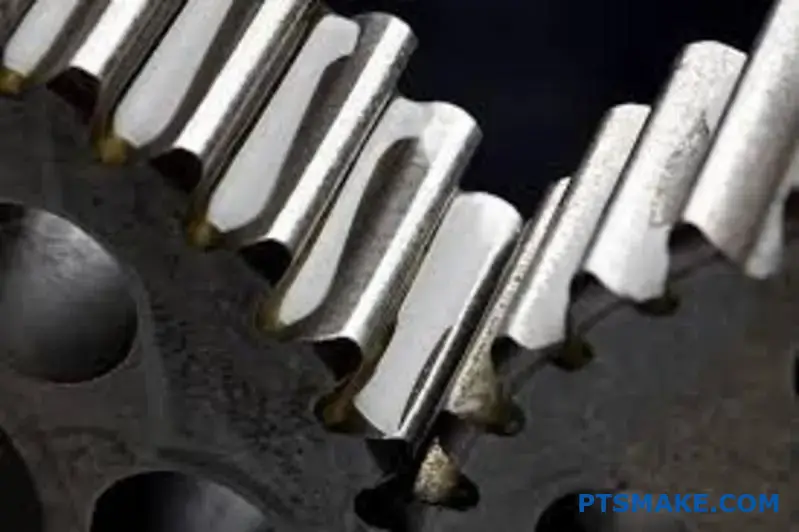
This type of failure leads to a complete tooth fracture. A crack initiates at the root of the tooth, where bending stresses are at their highest.
Surface Contact Fatigue
This failure appears as pitting on the working surfaces of the teeth. It’s caused by high, repeated contact pressure during meshing.
These two mechanisms dictate a gear’s service life.
| Failure Mode | Location | Primary Cause |
|---|---|---|
| Bending Fatigue | Tooth Root | Repeated Bending Stress |
| Surface Fatigue | Tooth Flank | High Contact Stress |
Gears are foundational components in power transmission. Their design must anticipate and prevent failure. Let’s look closer at the mechanisms that every engineer must consider.
The Mechanism of Bending Fatigue
Think of a gear tooth as a small cantilever beam. Each time it engages with another tooth, especially from a powerful driving gear, it bends. This load creates maximum tensile stress at the root fillet on the loaded side.
With every rotation, this stress cycles from zero to maximum and back again. Over millions of cycles, a microscopic fatigue crack can form. This crack slowly grows until the remaining material can no longer support the load. The result is a sudden, complete fracture of the tooth.
The Onset of Surface Fatigue (Pitting)
The contact between mating gear teeth creates extremely high localized pressure on the tooth flanks. This stress is highest just below the contact surface.
These repeated high pressures generate subsurface shear stresses6. These stresses can initiate microscopic cracks beneath the surface. Over time, these cracks grow towards the surface. When one breaks through, a small piece of material detaches, leaving a pit. This process is known as pitting.
| Characteristic | Bending Fatigue (Fracture) | Surface Fatigue (Pitting) |
|---|---|---|
| Initiation Point | Tooth Root Fillet | Tooth Flank (Subsurface) |
| Stress Type | Bending (Tensile) Stress | Compressive Contact Stress |
| Result | Complete Tooth Breakage | Pits on Tooth Surface |
| Severity | Often Catastrophic | Gradual Degradation |
In summary, gear teeth fail in two ways. Bending fatigue causes a catastrophic fracture at the root. Surface contact fatigue leads to gradual pitting on the flank. Both failure modes must be accounted for in every robust gear design to ensure longevity and reliability.
How does center distance tolerance impact a gear mesh?
An incorrect center distance is a critical error. It directly harms the gear mesh’s performance and lifespan. Even a small deviation from the specified tolerance can cause major problems.
These issues range from annoying operational noise to complete system failure. Proper control of this dimension is essential for reliable gear operation.
| Consequence | Description | Severity |
|---|---|---|
| Increased Noise | Gears whine or click during operation. | High |
| Accelerated Wear | Tooth surfaces degrade prematurely. | High |
| Catastrophic Failure | Teeth can break, causing system shutdown. | Critical |
This is not something to overlook in design or manufacturing.
When the center distance is incorrect, it changes the fundamental geometry of the gear engagement. This directly alters how the teeth interact, leading to predictable but damaging outcomes. The two most significant changes are to the operating pressure angle and backlash.
Altered Operating Pressure Angle
A center distance that is too large increases the operating pressure angle7. This puts more radial force on the shafts and bearings, which can lead to premature wear on those components. It also concentrates the load on a smaller area of the tooth, increasing contact stress.
Conversely, a center distance that is too small reduces the pressure angle. This might seem good, but it often leads to gear teeth tips digging into the root of the mating gear, a condition known as interference.
Impact on Backlash
Backlash is the clearance between mating teeth. An incorrect center distance directly affects it. The relationship is straightforward.
| Center Distance | Backlash Effect | Potential Problem |
|---|---|---|
| Too Large | Increases Backlash | Impact loads, noise, tooth hammering |
| Too Small | Decreases Backlash | Binding, excessive heat, lubrication failure |
At PTSMAKE, we ensure our CNC machining processes hold tight tolerances on housing and shaft locations. This control is vital for any assembly involving a driving gear, as it guarantees the designed backlash and pressure angle are maintained for smooth, quiet operation.
In short, incorrect center distance is a primary cause of gear system failure. It negatively alters the operating pressure angle and backlash, leading to issues like noise, excessive wear, and potential tooth breakage.
What fundamental forces act on a single gear tooth?
The tangential force we discussed is the primary driver of motion. However, it doesn’t act alone. To truly grasp gear tooth stress, we must break this force down.
This force resolves into two key components. These are the normal force and the radial force. Understanding this split is critical. It is the foundation for calculating bending stress and analyzing bearing loads accurately.
| Force Component | Primary Effect |
|---|---|
| Normal Force | Causes contact stress |
| Radial Force | Pushes gears apart |
This deconstruction helps us move from a simple model to a precise engineering analysis.
The transmitted force from the driving gear is not as simple as one vector. It’s a combination of forces that must be managed. The key to understanding this is the pressure angle of the gear. This angle dictates how the tangential force is split.
The Normal and Radial Components
The total force on a gear tooth acts along the line of action. This line is perpendicular to the tooth surface at the point of contact. This total force is what we call the normal force.
Normal Force: The True Pressure
This is the actual force pressing one tooth against another. It’s the source of Hertzian contact stress. It is also the hypotenuse in our force triangle. Its magnitude depends on the tangential force and the pressure angle.
Radial Force: The Separating Push
This component acts toward the center of the gear. It does no useful work in transmitting torque. Instead, it pushes the two gears apart from their Pitch Circle8. This radial force directly loads the shafts and bearings. Ignoring it leads to premature bearing failure.
In our work at PTSMAKE, we analyze these components carefully. This ensures that not only the gears, but the entire assembly, including shafts and bearings, can handle the operational loads without failure.
| Force | Direction | Key Impact |
|---|---|---|
| Normal Force | Perpendicular to the tooth surface at contact point | Contact Stress, Wear |
| Radial Force | Towards the gear’s center | Bearing Load, Deflection |
Decomposing the tangential force is not just an academic exercise. It’s essential for practical design. Splitting it into normal and radial components allows us to calculate bending stress and bearing loads, preventing critical failures in the gear system.
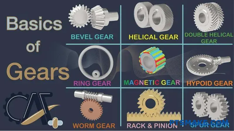
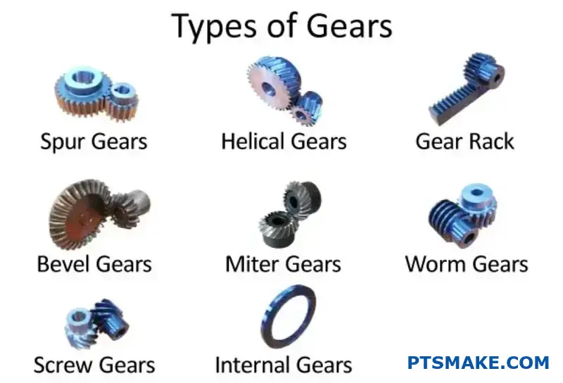
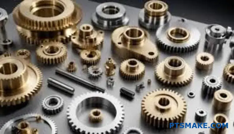
How do you classify common types of driving gears?
A great way to classify gears is by their shaft orientation. This simple method helps you quickly narrow down choices for your design. It creates a clear mental model.
Think of it as a decision tree. First, ask how the input and output shafts are positioned relative to each other. Are they parallel? Do they intersect? Or do they cross without intersecting? Answering this guides your selection.
Below is a basic breakdown.
| Shaft Orientation | Description |
|---|---|
| Parallel Shafts | Shafts run in the same plane and never meet. |
| Intersecting Shafts | Shafts are in the same plane and cross at a point. |
| Non-Intersecting | Shafts are in different planes and do not cross. |
Each category contains specific types of driving gears.
Let’s expand on this classification system. In our projects at PTSMAKE, this is often the first step we take with clients. It clarifies the design intent right away. This simple framework removes complexity from the gear selection process.
Parallel Shafts
When shafts run parallel, your choices are straightforward. Spur gears are the most common. Helical gears are another excellent option. They offer smoother and quieter operation due to their angled teeth. The main trade-off is the axial thrust they generate.
Intersecting Shafts
For shafts that intersect, usually at a 90-degree angle, bevel gears are the standard solution. Their conical shape allows them to transfer motion between intersecting axes. The gear teeth can be straight, spiral, or hypoid, depending on the application’s needs.
Non-Intersecting, Non-Parallel Shafts
This category is unique. The shafts cross in different planes. The classic example is a worm gear system. This setup provides a large speed reduction in a compact space. The a pitch surface9 of the gears is what allows this unique motion transfer.
Here is a more detailed map.
| Shaft Orientation | Common Gear Types | Key Feature |
|---|---|---|
| Parallel | Spur, Helical | Simple motion transfer; efficient. |
| Intersecting | Bevel | Changes the direction of power transmission. |
| Non-Intersecting | Worm, Crossed-Helical | High gear ratios in a single stage. |
Classifying gears by shaft orientation is a powerful first step. This mental model simplifies the selection process by aligning gear types directly with their primary mechanical function. It helps ensure you choose the right driving gear for your system’s layout.
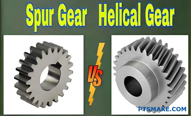
When should you choose a helical gear over a spur gear?
Choosing the right gear is crucial for performance. It’s not always a simple decision. The choice between a spur and a helical gear depends on your specific application needs.
We need to look at key factors. These include load, noise, and manufacturing complexity. A quick comparison can help guide your thinking.
| Feature | Spur Gear | Helical Gear |
|---|---|---|
| Tooth Orientation | Straight, parallel to axis | Angled to axis |
| Noise Level | Higher | Lower |
| Axial Thrust | None | Yes |
| Cost | Lower | Higher |
Understanding these differences is the first step. It helps you balance performance against budget for your project’s success.
Deeper Dive: Spur vs. Helical
Let’s break down the practical differences. The design of the gear teeth directly impacts how they perform in a system.
Load Capacity and Smoothness
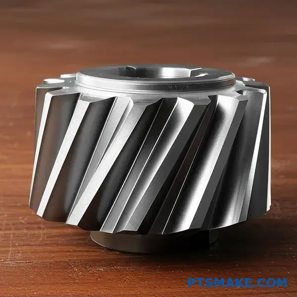
Helical gears have angled teeth. This means engagement is gradual. More than one tooth is in contact at any given time. This distributes the load better, leading to a higher load capacity and smoother power transmission. Spur gears engage along the entire tooth face at once.
Noise and Vibration
The sudden, full-tooth contact of spur gears creates noise and vibration. This is often unacceptable in consumer products or high-speed machinery. Helical gears, with their gradual engagement, are significantly quieter and run more smoothly. This makes them an ideal choice for a quiet Driving Gear.
The Challenge of Axial Thrust
The angle of helical gear teeth creates a side force. This force, known as axial thrust10, pushes the gear along its axis. This requires bearings, such as tapered roller bearings, to manage the force. Spur gears do not produce this thrust, simplifying bearing requirements.
Manufacturing Complexity and Cost
Here is a clear trade-off. Spur gears are simpler to design and machine. This makes them more cost-effective. Helical gears require more complex manufacturing processes due to the helix angle. At PTSMAKE, we use advanced CNC machining to produce them efficiently.
| Criterion | Spur Gear | Helical Gear | Application Implication |
|---|---|---|---|
| Contact | Line contact | Gradual, multiple teeth | Helical offers smoother, higher load transfer. |
| Noise | High | Low | Helical is preferred for quiet operation. |
| Thrust Load | No | Yes | Helical requires robust bearing support. |
| Efficiency | High (98-99%) | Slightly lower due to sliding | Minimal difference for most applications. |
| Cost | Lower | Higher | Spur gears are better for tight budgets. |
Your choice depends on balancing these factors. Helical gears provide superior performance for noise and load but come with added complexity and cost. Spur gears are a simple, cost-effective solution for applications where noise is not a major concern.
What are the unique applications for bevel and worm gears?
Choosing the right gear is crucial. It’s about matching the tool to the specific engineering challenge. Bevel and worm gears are not interchangeable. Each solves a distinct problem.
Bevel gears excel at changing power direction. Worm gears are masters of speed reduction. They also prevent back-driving. Understanding these differences is key to effective design.
| Gear Type | Primary Function |
|---|---|
| Bevel Gear | Changing direction of rotation (typically 90°) |
| Worm Gear | High speed reduction & anti-reversal |
This choice directly impacts your machine’s efficiency and reliability.
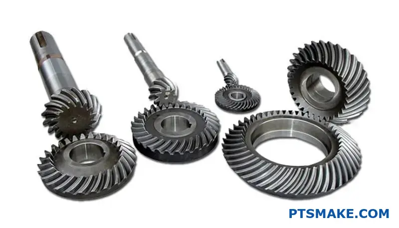
Scenarios for Bevel Gears
Bevel gears are the go-to solution when rotational power must turn a corner. Think of a hand drill. The motor spins horizontally, but the drill bit spins vertically. A pair of bevel gears makes this 90-degree transition possible.
Another classic example is an automotive differential. It allows the wheels to rotate at different speeds while turning. Spiral bevel gears are used here for their smooth, quiet operation at high speeds. Their ability to handle intersecting shafts is vital.
When to Choose Worm Gears
Worm gears are optimal for achieving massive gear reduction in a compact space. A single worm gear set can achieve reduction ratios of 100:1 or more. This is something other gear types struggle with.
Consider a conveyor system. The motor runs at high RPM, but the belt moves slowly with high torque. A worm gear drive is perfect for this. The worm acts as the driving gear. The system’s kinematics11 are straightforward and efficient.
Their best feature is often their self-locking nature. This prevents the load from driving the motor backward. It’s a built-in safety brake, essential for applications like lifts, hoists, and elevators.
| Application | Optimal Gear | Key Reason |
|---|---|---|
| Hand Drill | Bevel Gear | Changes motor rotation by 90° |
| Conveyor Belt | Worm Gear | High speed reduction, high torque |
| Automotive Differential | Bevel Gear | Transmits power around a corner |
| Elevator Hoist | Worm Gear | Self-locking for safety |
At PTSMAKE, we guide clients on these choices daily to ensure mechanical integrity.
Bevel gears are best for redirecting power, especially at 90-degree angles. Worm gears are unmatched for high gear reductions and applications requiring a non-reversing, self-locking mechanism. Each has a distinct, critical role in engineering design.
What defines a simple, compound, and planetary gear train?
Understanding gear trains begins with their structure. Each configuration is a specific solution to a mechanical problem. It’s not just about meshing teeth.
The arrangement of gears dictates the final output. This includes speed, torque, and the physical space it occupies.
Simple Gear Train
This is the most basic setup. Gears are arranged in a line, each on its own shaft.
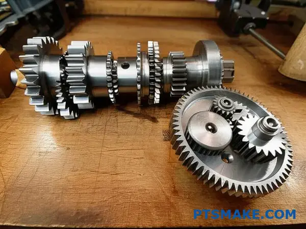
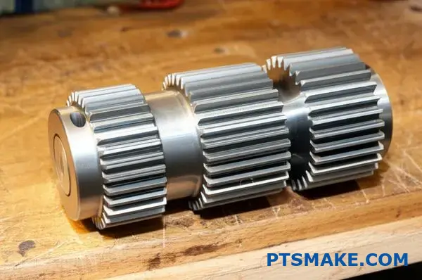
Compound Gear Train
Here, at least one shaft holds more than one gear. This allows for greater ratio changes.
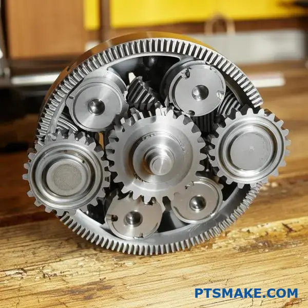
Planetary Gear Train
This compact system has a central "sun" gear. Multiple "planet" gears rotate around it, all held within an outer "ring" gear.
| Gear Train Type | Structural Hallmark | Primary Goal |
|---|---|---|
| Simple | Each gear on a separate shaft, in series. | Basic speed/torque modification. |
| Compound | Multiple gears on a common shaft. | Large speed reduction in a small space. |
| Planetary | Sun, planet, and ring gear arrangement. | High torque, compactness, coaxial input/output. |
How Structure Dictates Function
The physical layout of a gear train is everything. At PTSMAKE, we often guide clients through these choices. The decision impacts the final product’s performance and size.
Simple Trains: Direct and Linear
In a simple gear train, power flows linearly. It moves from one gear to the next. The ratio is determined solely by the first and last gears. The intermediate gears, or idlers, only change the direction of rotation.
Compound Trains: Space Efficiency
Compound trains are clever. By placing two gears of different sizes on the same shaft, you can create a large gear ratio in a compact form. The output of the first pair becomes the input for the second, all on one shared axle. This is a common solution we see in projects needing significant speed reduction without a large footprint. The initial Driving Gear selection is critical here.
Planetary Trains: Power and Precision
Planetary, or epicyclic, systems are the most complex structurally. They offer high power density. This means they can handle significant Torque multiplication12 in a very small package. The load is shared among several planet gears. This distribution reduces stress on individual teeth and allows for smooth, reliable operation. This makes them ideal for applications from automatic transmissions to robotic arms.
| Feature | Simple Gear Train | Compound Gear Train | Planetary Gear Train |
|---|---|---|---|
| Arrangement | Linear | Stacked on shafts | concentric (sun, planet, ring) |
| Space Usage | Can be lengthy | Compact for high ratios | Very compact |
| Torque Capacity | Low to Moderate | Moderate to High | Very High |
| Complexity | Low | Moderate | High |
In short, the structural differences between simple, compound, and planetary gear trains are deliberate. Each design offers a unique combination of speed, torque, and size benefits. Choosing the right one is crucial for your application’s success.
How do planetary gear systems enable unique power flow paths?
Planetary gear systems are ingeniously simple in structure. They consist of three main parts. This design is what allows for such unique power flows.
Core Components
The system has a central sun gear. Multiple planet gears orbit it. An outer ring gear with internal teeth encloses them all.
| Component | Role |
|---|---|
| Sun Gear | The central gear |
| Planet Gears | Orbit the sun gear |
| Ring Gear | The outer, internal-toothed gear |
By holding one of these components stationary, you can completely change the output. This versatility is their greatest strength.
This modular function is why the epicyclic train13 is a cornerstone in modern transmissions and machinery. The ability to switch roles between input, output, and a stationary element is what creates these unique power flow paths. In past projects at PTSMAKE, we’ve leveraged this for complex robotic applications.
Achieving Gear Reduction
For gear reduction, we typically use the sun gear as the input. The ring gear is held stationary.
The planet carrier becomes the output. This setup significantly increases torque while reducing speed. The planet gears effectively become the final driving gear mechanism, transferring power to the carrier.
Creating Overdrive
To achieve overdrive, the roles are switched. The planet carrier acts as the input.
The sun gear is held stationary. The ring gear then becomes the output component. This configuration results in an output speed that is higher than the input speed, which is ideal for efficiency at high speeds.
Enabling Reverse Motion
For reverse, the planet carrier is held stationary. The sun gear is the input.
This forces the planet gears to act as idlers. They transfer motion to the ring gear, causing it to rotate in the opposite direction of the sun gear.
| Mode | Input Component | Stationary Component | Output Component | Result |
|---|---|---|---|---|
| Reduction | Sun Gear | Ring Gear | Planet Carrier | Torque Up, Speed Down |
| Overdrive | Planet Carrier | Sun Gear | Ring Gear | Speed Up, Torque Down |
| Reverse | Sun Gear | Planet Carrier | Ring Gear | Direction Change |
The elegance of a planetary gearset lies in its three-component structure. By strategically holding one part stationary—the sun, ring, or planet carrier—we can create vastly different outputs like reduction, overdrive, or reverse from one compact assembly.
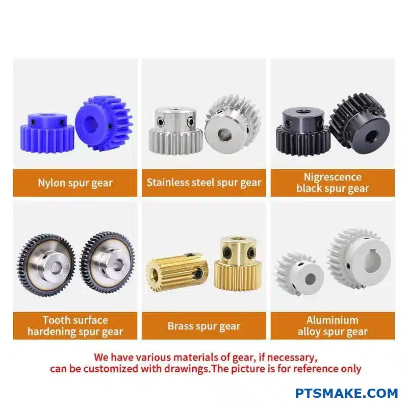
What is the system-level trade-off between different gear materials?
Choosing the right gear material is a critical decision. It directly impacts performance, lifespan, and cost. Each material offers a unique set of properties.
Engineers must balance these factors carefully. The ideal choice for a high-torque driving gear will differ from a low-load application.
Common Gear Materials Overview
Let’s compare four common material types. Each has distinct advantages and disadvantages. This balance is key to system design.
| Material | Key Advantage | Common Use Case |
|---|---|---|
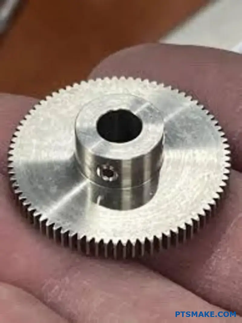
| Carbon Steel | Low Cost | General Machinery |
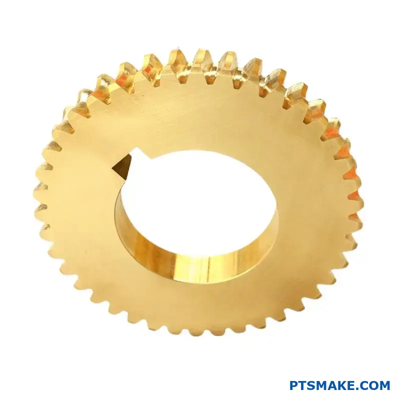
| Alloy Steel | High Strength | Automotive Transmissions |
| Bronze | Low Friction | Worm Gears |
| Polymers | Lightweight, Quiet | Consumer Electronics |
This table provides a quick reference. But a deeper analysis is needed for a final decision.
Making the right choice involves a detailed trade-off analysis. At PTSMAKE, we guide clients using a decision matrix. This clarifies priorities for each unique project.
Decision Matrix for Gear Materials
This matrix helps visualize the compromises. We rate each material from Low to Very High based on key criteria. This data is based on our internal testing and project experience.
| Material | Strength | Wear Resistance | Cost | Weight |
|---|---|---|---|---|
| Carbon Steel | Medium | Medium | Low | High |
| Alloy Steel | Very High | High | Medium | High |
| Bronze | Low-Medium | High | High | High |
| Polymers (e.g., Nylon, PEEK) | Low | Low-Medium | Low-High | Very Low |
Deeper Analysis of Trade-offs
Alloy steels offer top-tier strength. But they come with higher costs and weight. This makes them ideal for demanding industrial or automotive systems.
Polymers are excellent for reducing noise and weight. However, their lower strength limits their use in high-load scenarios. Their tribological properties14 can vary greatly between different polymer types.
Bronze is a specialized choice. It is often paired with a steel worm gear. It provides excellent wear resistance in high-friction sliding contact but at a significant cost.
Selecting a gear material is a balancing act. The decision matrix simplifies this complex process. It helps you weigh strength against cost and wear resistance against weight, ensuring the final choice aligns perfectly with your system’s requirements and budget.
How do heat treatment processes alter a gear’s properties?
Heat treatment is not a one-size-fits-all solution. Different methods achieve specific results. The goal is often the same: a hard, wear-resistant surface with a tough, impact-resistant core.
This balance is crucial for gear longevity. Let’s explore three common processes we use at PTSMAKE to achieve this.
Key Heat Treatment Methods
Each method serves a distinct purpose. The choice depends on the gear’s material and its intended application.
| Treatment | Primary Goal | Core Property |
|---|---|---|
| Through-Hardening | Uniform Hardness | Hard |
| Carburizing | Hard Surface | Tough |
| Nitriding | Very Hard Surface | Tough |
Choosing the right heat treatment is critical. It directly impacts the performance and reliability of the gear in its final assembly. It’s a step where precision matters immensely.
Through-Hardening Explained
Through-hardening, or quenching and tempering, heats the entire gear. This process creates uniform hardness and strength throughout the part. It’s suitable for gears that need consistent properties from surface to core. However, it can sometimes result in brittleness if not tempered correctly.
Surface Hardening Techniques
For applications needing a durable surface and a ductile core, surface treatments are ideal. These methods fall under the umbrella of case hardening15.
Carburizing
Carburizing introduces carbon into the surface of low-carbon steel. This creates a hard, carbon-rich outer layer while the core remains tough and ductile. This process is excellent for a Driving Gear that faces high contact stress and shock loads.
Nitriding
Nitriding uses nitrogen to harden the surface. It is performed at lower temperatures than carburizing. This minimizes distortion, a huge benefit for high-precision gears. The resulting surface is extremely hard and corrosion-resistant.
| Feature | Carburizing | Nitriding |
|---|---|---|
| Process Temp | High | Low |
| Case Depth | Deeper | Shallower |
| Distortion Risk | Higher | Lower |
| Surface Hardness | Very Hard | Extremely Hard |
Heat treatments are essential for optimizing gear performance. Through-hardening creates uniform strength, while methods like carburizing and nitriding provide a hard, wear-resistant surface and a tough, shock-absorbent core, extending the gear’s operational life.
What information is essential on a gear manufacturing drawing?
A gear drawing is a contract between the designer and manufacturer. Missing information leads to errors. It is that simple. Clear specifications are vital.
They ensure the final part, especially a driving gear, performs correctly. Every detail matters for function and fit.
Key Geometric Parameters
These numbers define the gear’s basic shape and size. They are the foundation of the design.
| Parameter | Justification |
|---|---|
| Module/Diametral Pitch | Defines the tooth size. It must match the mating gear. |
| Number of Teeth | Determines the gear’s speed ratio and diameter. |
| Pressure Angle | Affects the tooth shape and load-carrying capacity. |
| Helix Angle (if applicable) | For helical gears, it dictates thrust load and engagement. |
Material & Hardness
The choice of material dictates the gear’s strength. Heat treatment specifications determine its wear resistance and overall durability. It’s a critical combination.
Beyond Geometry: Material and Treatment
A gear is more than its dimensions. The material choice is crucial. Steels like 4140 or 8620 are common, but the specific application dictates the best option. The drawing must clearly state the material.
Heat treatment follows. Processes like carburizing or nitriding harden the surface. This improves wear resistance without making the core brittle. The required case depth and surface hardness must be on the drawing. This prevents premature failure under load.
Defining Quality and Precision
Finally, quality specifications control manufacturing accuracy. These tolerances are not suggestions; they are requirements. They ensure the gear operates smoothly and quietly. Even a small profile deviation16 can lead to significant operational noise and wear.
At PTSMAKE, we find that drawings with clear quality grades, like AGMA or ISO standards, are most effective. This removes ambiguity for everyone involved. A high-quality driving gear relies on these tight controls.
| Quality Specification | Purpose |
|---|---|
| Tooth Profile Tolerance | Controls the accuracy of the tooth curve shape. |
| Total Runout | Ensures the gear rotates concentrically on its axis. |
| Tooth Alignment | Manages the parallelism of the tooth along its face. |
| Surface Finish | Affects friction, lubrication, and operational noise. |
A successful gear begins with a complete drawing. It must clearly define geometry, material, heat treatment, and quality specifications. This clarity prevents costly errors and ensures the final part meets every performance requirement without question.
How are AGMA/ISO standards used to structure gear design?
AGMA and ISO are the rulebooks for gear design. They create a universal language for engineers worldwide. This common ground is essential.
It ensures everyone agrees on gear ratings. It also defines quality and testing methods. This removes guesswork and builds trust.
| Standard | Primary Focus Area |
|---|---|
| AGMA | Primarily North American, detailed specs |
| ISO | International, broad framework |
At PTSMAKE, these standards are vital. They help us communicate clearly with clients globally. We deliver parts that meet exact specifications.
The Framework for Rating, Quality, and Testing
These standards provide a clear structure. They guide the entire gear design and manufacturing process from start to finish. It’s a blueprint for reliability.
A Common Language for Gear Rating
How do we know a gear is strong enough? Standards provide the formulas. They define how to calculate stress limits for materials and designs.
This includes calculations for bending strength and surface durability. These are critical for any gear, especially a primary driving gear. This ensures the gear can handle its intended load without failing. It’s all based on proven engineering principles.
Defining Gear Quality with Numbers
AGMA and ISO use quality numbers. A higher number means tighter tolerances and greater precision. This directly affects performance and cost.
For example, a high-quality number demands a very precise involute profile17. This precision reduces noise and vibration. Choosing the right quality level is a key decision. It’s about balancing performance needs with the project budget.
| Quality Factor | Controlled By | Impact on Performance |
|---|---|---|
| Tooth Profile Accuracy | AGMA/ISO Quality No. | Smoothness, Noise Level |
| Pitch Deviation | AGMA/ISO Quality No. | Load Distribution, Vibration |
| Runout | AGMA/ISO Quality No. | Rotational Accuracy |
Standardizing Inspection
Finally, standards dictate how to test gears. They specify the methods and equipment for inspection. This ensures consistency. A gear we test at PTSMAKE will show the same results when tested by our client. This shared understanding is the foundation of trust.
AGMA and ISO are more than just documents. They are the foundation of modern gear design. They provide a common language that ensures reliability, quality, and clear communication between designers, manufacturers, and clients. This framework is essential for predictable outcomes.
How do you select an appropriate material and heat treatment?
Choosing the right material isn’t about guesswork. It’s a process that starts with solid engineering principles. First, we must calculate the stresses your part will face.
This initial calculation gives us a baseline. For a component like a Driving Gear, we analyze forces during operation. This helps determine the minimum strength needed.
Initial Stress Calculation
We start by defining the load conditions. Then we apply engineering formulas. This gives us the theoretical stress value for the part.
| Parameter | Description | Example Value |
|---|---|---|
| Load (Force) | The force applied to the part. | 500 N |
| Cross-Sectional Area | The area resisting the force. | 100 mm² |
| Calculated Stress | Force divided by Area. | 5 MPa |
This is our starting point. But real-world conditions are never this simple. We must account for more factors.
The next step is crucial. We apply service factors. These are multipliers that account for real-world operating conditions. This moves us from theoretical stress to a required material strength.
Adjusting for Service Factors
A calculated stress of 5 MPa is not the final number. We must consider how the part is used. Is the load steady or does it involve impacts?
A service factor18 helps bridge this gap. It’s a safety multiplier. We use it to adjust the calculated stress. This ensures the material can handle unexpected events.
For example, a part with sudden loads needs a higher factor. This increases the required strength of the material we select.
Reliability and Material Choice
We also consider the required reliability. A critical component in aerospace demands a higher safety margin. A non-critical part might not.
This all leads to the "allowable stress." This is the maximum stress a material can safely handle in that specific application. We then choose a material whose properties exceed this value.
| Factor | Description | Typical Multiplier |
|---|---|---|
| Load Type | Accounts for shock or impact. | 1.2 – 2.0 |
| Temperature | For performance at high/low temps. | 1.1 – 1.5 |
| Reliability | Critical vs. non-critical parts. | 1.25 – 2.5 |
At PTSMAKE, we work with you to define these factors. This ensures the final part is both safe and cost-effective.
Material selection starts with calculating baseline stress. We then apply service factors for load type and reliability. This determines the required allowable stress, guiding us to the perfect material for your component’s long-term performance.
How do you determine the required face width of a gear?
Choosing the right gear face width is a critical balancing act. A wider face can distribute load over a larger area. This generally reduces stress on the gear teeth.
However, a face width that is too wide can cause problems. It can lead to uneven load distribution, especially if there are alignment issues. This can actually increase stress and lead to premature failure.
Understanding the Trade-offs
The goal is to find the sweet spot. You want a width that is sufficient to handle the load without being overly sensitive to manufacturing and assembly variations.
Face Width, Load Distribution, and Stress
The connection between these three elements is fundamental in gear design. A wider face provides more contact area. This, in theory, lowers both contact and bending stresses on the teeth. A powerful driving gear often requires a substantial face width to transmit torque effectively.
But reality is more complex. Shafts can deflect under load, and manufacturing tolerances exist. These factors can prevent the load from spreading evenly across the entire face width. Instead, the load concentrates on one end of the tooth. This load concentration19 creates a high-stress point, defeating the purpose of a wider face.
In past projects at PTSMAKE, we’ve seen designs fail because of this. A gear with a theoretically safe wide face failed because minor misalignment caused severe edge loading. Precise manufacturing and rigid mounting are essential for wider gears.
Practical Guidelines
Engineers often use rules of thumb as a starting point. These guidelines relate face width (b) to other gear parameters like the pinion pitch diameter (d) or module (m). Here are some common starting points:
| Gear Type | Face Width (b) Guideline |
|---|---|
| Spur Gears | 8 < b/m < 16 |
| Helical | b < 2 * d (Pinion) |
| Bevel Gears | b < L/3 (Cone Distance) |
These are not strict rules. You must consider the specific application, material, and expected manufacturing quality.
A wider face can lower stress, but only with even load distribution. Misalignment and deflection can negate this benefit by concentrating the load. Your final design choice must balance theoretical strength with practical manufacturing and assembly realities.
How do you check for geometric interference in a gear design?
Geometric interference can silently sabotage a gear system. It’s crucial to identify and prevent it early in the design phase.
There are two primary types we look for. One is involute interference, often called undercutting.
Involute Interference (Undercutting)
This happens when the cutting tool removes material from the base of the gear tooth. This action significantly weakens the tooth.
Trochoidal Interference
This occurs when the tip of one gear tooth digs into the root fillet of its mating gear, causing damage.
Here is a quick comparison:
| Interference Type | Cause | Consequence |
|---|---|---|
| Involute | Cutting tool removes base material | Weaker tooth root, risk of fracture |
| Trochoidal | Gear tip digs into root fillet | Premature wear, noise, and failure |
Checking for these issues prevents failure and ensures smooth operation.
Detection Methods: CAD and Calculation
In modern design, we rely heavily on CAD software. These tools simulate gear meshing and automatically flag potential interference points. This method is fast and highly accurate for most applications.
However, understanding the underlying principles is key. Manual calculations based on gear geometry—like the number of teeth, module, and pressure angle—can also predict interference. This is useful in the early design stages.
The Solution: Profile Shifting
Once interference is detected, one of the most effective solutions is profile shifting. This involves modifying the gear tooth profile during manufacturing.
What is Profile Shifting?
We adjust the radial position of the cutting tool relative to the gear center. A positive shift moves the tool away from the center. This creates a thicker, stronger tooth at the root.
This technique is essential for preventing both undercutting and trochoidal interference20. It’s a standard practice in our projects at PTSMAKE to optimize gear performance. For a critical Driving Gear, this can be the difference between success and failure.
Here’s how profile shifting impacts gear design:
| Shift Type | Effect on Tooth Root | Effect on Tooth Tip | Application |
|---|---|---|---|
| Positive | Thicker, stronger | Thinner, more pointed | Prevents undercutting in small pinions |
| Negative | Thinner, weaker | Thicker, flatter | Adjusts center distance |
Proper application of this method ensures robust and efficient gear trains.
In short, checking for involute and trochoidal interference is vital. We use CAD analysis and calculations. Design modifications, especially profile shifting, are key to creating a robust, interference-free gear design that avoids premature wear and failure.
How do you mitigate gear noise (NVH) in a sensitive application?
Solving gear noise in sensitive applications is about targeted design changes. It’s not one single fix. It’s a combination of smart engineering choices.
Choosing the Right Gear Type
Helical gears are often my first recommendation over spur gears. The angled teeth engage gradually, which significantly reduces impact noise.
Optimizing Gear Tooth Design
Improving tooth profile accuracy is non-negotiable. It ensures smooth power transmission. We also focus on increasing the contact ratio.
| Feature | Spur Gear | Helical Gear |
|---|---|---|
| Tooth Engagement | Abrupt | Gradual |
| Axial Thrust | None | Generated |
| Noise Level | Higher | Lower |
Rethinking the Housing
Finally, the housing itself can be a source of noise amplification. A well-designed, rigid housing can dampen vibrations effectively.
Specific Design Strategies in Practice
Let’s dive deeper into how these changes create a quieter system. Moving from a spur gear to a helical gear is a powerful first step. The angled teeth allow for a smoother, more gradual load transfer between teeth. This minimizes the sudden meshing impact that causes noise.
The Importance of Contact Ratio
Increasing the contact ratio is another key strategy. This means ensuring more than one pair of teeth are in contact at all times. A higher contact ratio distributes the load over a larger area. This reduces stress on individual teeth and smooths out the transmission of power, directly lowering vibration.
Precision in Tooth Profile
The accuracy of the driving gear’s tooth profile is critical. We use high-precision CNC machining at PTSMAKE to achieve this. Perfect tooth geometry ensures proper Conjugate Action21, which is essential for constant velocity transfer and minimal noise. Even microscopic deviations can introduce significant NVH issues.
Housing Design and Material Selection
The housing acts like a speaker, amplifying any internal vibrations. By increasing its stiffness and using damping materials, we can contain the noise.
| Housing Material | Damping Capability | Relative Cost |
|---|---|---|
| Cast Iron | Good | Medium |
| Aluminum | Fair | Low |
| Polymer Composite | Excellent | High |
This multi-faceted approach, combining gear geometry, precision manufacturing, and structural design, yields the best results for sensitive applications.
Effective NVH mitigation isn’t about a single solution. It requires a holistic approach, combining helical gears, high contact ratios, precise tooth profiles, and a rigid, well-designed housing to achieve the quietest possible operation.
Ready to Elevate Your Driving Gear Projects? Choose PTSMAKE!
Unlock next-level precision for your driving gear design and manufacturing challenges with PTSMAKE. Submit your RFQ today and experience industry-leading expertise—engineered for quality, reliability, and on-time delivery—from prototype through production. Let’s build tomorrow’s gears together!

Understand this key concept for precise gear design and function. ↩
Learn more about this core principle of how force moves between gear teeth. ↩
Explore the kinematic principle ensuring a constant velocity ratio between meshing gears. ↩
Explore how temperature changes material size and its critical impact on mechanical engineering designs. ↩
Learn more about the critical process of gear tooth engagement and its geometric principles. ↩
Learn how Hertzian contact theory helps predict the initiation of pitting failure in gears. ↩
Learn more about how this critical angle dictates gear forces and contact stress. ↩
Learn more about this fundamental gear parameter and its impact on force transmission. ↩
Explore this link for a deeper dive into the geometry of gear meshing. ↩
Click to understand how this force impacts your design and bearing selection. ↩
Understand how gear geometry affects motion to improve your mechanical designs. ↩
Explore how gear ratios directly increase force output in mechanical systems. ↩
Discover the core kinematic principles that define this powerful and versatile gear system. ↩
Understand how surface interactions affect gear wear, friction, and overall lifespan. ↩
Explore this surface hardening method to understand how it boosts gear durability and wear resistance. ↩
Learn how this critical tolerance impacts gear performance and service life in our detailed technical guide. ↩
Learn about the crucial gear tooth curve that ensures constant, smooth power transmission. ↩
Learn how these multipliers ensure your part’s safety and longevity under real-world operating conditions. ↩
Learn how this factor critically impacts gear design and can lead to premature failure if ignored. ↩
Learn more about this complex interference type and see visual examples of how it occurs in gear meshes. ↩
Understand the fundamental principle of smooth gear motion and how it directly impacts noise and vibration reduction. ↩