Getting the bearing fit tolerance wrong can turn a precision component into an expensive failure. Your bearing either seizes from excessive interference or develops destructive creep from insufficient contact, leading to costly downtime and premature replacement.
Bearing fit tolerance determines the interference or clearance between the bearing ring and its mating surface (shaft or housing), controlling how securely the bearing is held in place to prevent relative motion while allowing proper assembly and thermal expansion.

This guide covers the engineering principles behind fit selection, from load zone analysis to thermal considerations. I’ll walk you through the practical decision-making process that helps you avoid common fitting mistakes and select the right tolerance for your specific application requirements.
What is the first principle of bearing fit selection?
When selecting a bearing fit, what’s the one rule that trumps all others? It’s simple: prevent relative motion between mating parts. This unwanted movement, often called creep, can cause serious damage.
The primary goal is to secure the bearing ring. You need a fit that’s tight enough to stop it from spinning inside the housing or on the shaft under load.
The Core Conflict
However, the fit can’t be excessively tight. You must also consider practical factors. This includes ease of assembly, future disassembly for maintenance, and the effects of temperature changes during operation.
Balancing Fit Types
The choice boils down to managing interference and clearance.
| Fit Type | Primary Goal | Key Consideration |
|---|---|---|
| Interference Fit | Prevents creep | Can be difficult to assemble |
| Clearance Fit | Allows easy assembly | Risk of creep if too loose |
Beyond the Basics: Understanding Rotational Loads
The first principle hinges on identifying which ring rotates. A rotating ring experiences a "rotating load." This means the load direction is stationary relative to that ring. This condition requires an interference fit to prevent creep.
Conversely, a stationary ring experiences a "stationary load." The load rotates relative to the ring. This typically allows for a looser, or clearance, fit. Misjudging this is a common mistake.
The Dangers of Creep
Creep isn’t just a minor slip. It generates heat and fine metal particles. This leads to a destructive wear process. Over time, this damage, known as fretting corrosion1, degrades both the bearing and its mating component.
This directly impacts the machine’s lifespan and reliability. In past projects at PTSMAKE, we’ve seen how precise CNC machining is essential to create the exact bearing fit tolerance required. Getting it right prevents these failures.
Fit Selection vs. Load Type
| Ring Condition | Load Type | Recommended Fit | Consequence of Wrong Fit |
|---|---|---|---|
| Inner Ring Rotates | Rotating | Interference | Creep on shaft |
| Outer Ring Rotates | Rotating | Interference | Creep in housing |
| Inner Ring Stationary | Stationary | Clearance | Excessive tightness |
This balance is key. You need enough grip to stop movement but not so much that it damages parts during assembly or operation due to thermal expansion.
The core principle of bearing fit selection is preventing relative motion (creep) under load. This is balanced against practical needs like assembly, maintenance, and thermal effects. The correct bearing fit tolerance is critical for machine longevity.
How does interference fundamentally differ from clearance?
Many see fits as just ‘tight’ or ‘loose’. But the distinction is more profound. It’s about intentional stress versus free space.
An interference fit actively creates internal forces. This preloads the assembly, locking parts together with friction.
A clearance fit provides a gap. This is crucial for parts that need to move, rotate, or expand with heat.
The Core Mechanical States
Understanding the state of the parts is key. One is static and stressed, the other dynamic and free.
| Feature | Interference Fit | Clearance Fit |
|---|---|---|
| Core Principle | Negative Allowance | Positive Allowance |
| Part Interaction | Constant Pressure | Free Movement |
| Primary Goal | Frictional Holding | Rotational Freedom |
The Physics of an Interference Fit
An interference fit works by force. The shaft is slightly larger than the hole. Pressing them together causes the materials to deform.
This forced deformation creates immense pressure between the surfaces. This pressure results in a strong frictional force that holds the assembly together, even under significant torque.
Stress Induction and Its Purpose
The outer part (housing) is stretched, putting it in tension. The inner part (shaft) is compressed. This creates hoop stress in both components.
This induced stress is not a flaw. It is the entire point. It’s the mechanism that transmits torque and resists axial forces without needing keys or bolts. Precise control of the bearing fit tolerance is essential here.
How Loads are Transmitted
The transmission method is the true difference. One relies on friction, the other on mechanical locking.
In our work at PTSMAKE, we see how this choice impacts design. Interference fits are clean and strong. They rely on the elastic deformation2 of the materials.
Clearance fits need extra features like keys or splines. These features physically block rotation to transfer loads.
| Load Transmission | Interference Fit | Clearance Fit |
|---|---|---|
| Mechanism | Static Friction | Mechanical Interlock (e.g., keys) |
| Stress State | Pre-stressed | Unstressed (at rest) |
| Key Factor | Material Properties | Keyway/Spline Geometry |
The difference is fundamental. Interference fits use engineered stress and friction to transmit loads and lock parts. Clearance fits use space to allow free movement, requiring separate features for load transmission.
What primary problem does the correct fit tolerance solve?
The main goal is simple. We need to make sure the bearing works exactly as it was designed.
This involves securing the correct ring. It also prevents premature wear. The result is a much longer operational life for the component.
The Central Challenge
The core task is to control the fit. We want to avoid any unwanted movement. At the same time, we must prevent excessive stress on the parts. It’s a delicate balance.
| Fit Issue | Consequence |
|---|---|
| Too Loose | Ring slippage, vibration, wear |
| Too Tight | High heat, premature failure |
Securing the Right Component
A bearing has an inner and outer ring. One is stationary, while the other rotates. The correct fit tolerance ensures the rotating ring is securely fixed to its shaft or housing.
If the fit is too loose, the ring can slip. This phenomenon, known as creep, generates heat and microscopic wear particles. This leads to vibration and eventual failure.
Preventing Premature Wear and Maximizing Life
The right fit distributes the load evenly across the bearing elements. This is crucial for performance. An improper fit creates stress concentrations on small areas.
This localized stress significantly shortens the bearing’s life. It can also cause secondary damage. For example, issues like fretting corrosion3 can degrade the mounting surfaces. In past projects at PTSMAKE, we’ve seen how precise machining of mating surfaces is key. It prevents these subtle but destructive issues.
| Tolerance Focus | Primary Benefit |
|---|---|
| Preventing Looseness | Stops ring creep and vibration |
| Avoiding Tightness | Prevents overheating and stress |
| Precise Fit | Ensures even load distribution |
This balance is what we focus on. It ensures every component achieves its expected service life.
The primary challenge is balance. Correct bearing fit tolerance secures the rotating ring to prevent slippage and wear. This ensures even load distribution, preventing premature failure and maximizing the component’s operational lifespan.
The Dangers of Temperature Differentials in Assemblies
Temperature is not a static factor. Different parts of a machine often operate at varying temperatures. This differential is where the real trouble begins for fits.
Imagine a shaft running much hotter than its housing. The shaft expands more, squeezing the bearing. This can dangerously reduce the internal clearance.
Conversely, a hot housing can expand away from a cooler bearing. This loosens the fit. Both scenarios lead to premature failure.
Key Risks from Temperature Differentials
| Scenario | Primary Effect | Resulting Danger |
|---|---|---|
| Shaft Hotter than Housing | Fit Tightens | Bearing Seizure |
| Housing Hotter than Shaft | Fit Loosens | Bearing Creep |
This interaction is a core challenge in maintaining proper bearing fit tolerance over the machine’s life.
How Temperature Changes Lead to Failure
When we design for a specific fit, we do so at a standard temperature, typically room temperature. But machines rarely operate there. The heat generated by operation changes everything.
The Path to Seizure
In many applications, the shaft or inner ring gets hot faster than the outer ring and housing. This is common in high-speed electric motors or spindles.
As the inner ring expands, it consumes the bearing’s radial internal clearance4. If the initial fit was already tight, this extra expansion can eliminate the clearance entirely.
The result is seizure. The rolling elements get pinched, friction skyrockets, and the bearing fails catastrophically. In past projects at PTSMAKE, we’ve seen this happen when designs don’t account for thermal gradients.
The Onset of Creep
Now, consider the opposite. If the housing heats up significantly more than the bearing’s outer ring, the interference fit can be lost.
This allows the outer ring to spin within the housing, a phenomenon called "creep." This slipping action generates friction and wear on both the housing bore and the bearing.
It damages components and can lead to vibration and eventual failure. Selecting materials with similar thermal expansion properties is a key strategy we use to mitigate this risk.
| Component Temperature | Fit Change | Failure Mode | Example Application |
|---|---|---|---|
| Inner Ring > Outer Ring | Becomes Tighter | Seizure | High-Speed Spindles |
| Outer Ring > Inner Ring | Becomes Looser | Creep | Ovens, Hot Environments |
Temperature differentials directly alter the engineered fit between components. Ignoring these thermal effects can lead to critical failures like bearing seizure from excessive tightening or creep from a loosened fit, ultimately compromising the assembly’s performance and lifespan.
How Radial Load Creates the Load Zone
When a radial load is applied, it doesn’t spread evenly. The force concentrates on a small arc of the bearing raceway.
This arc is what we call the "load zone." It’s where the rolling elements actively support the weight.
The Arc of Support
Only a few rolling elements at the bottom handle the entire load. The ones at the top carry no load at all.
This focused pressure is critical. Understanding it helps us determine the correct bearing fit tolerance.
Visualizing the Force
Imagine the force pressing down. This creates a high-pressure zone on a limited section of the inner and outer rings.
| Bearing Position | Load Status |
|---|---|
| Top | No Load |
| Middle | Minimal Load |
| Bottom | Maximum Load |
This concentration of force dictates how the bearing components must be installed to prevent premature failure.
Rotating Ring vs. Stationary Ring
The key question is: which ring rotates relative to the load direction? This determines which part needs a tighter fit.
If the inner ring rotates, every point on its raceway passes through the load zone once per revolution. The load on the outer ring, however, remains fixed on one spot.
Why Tighter Fits Are Crucial
A rotating ring that continuously enters the load zone needs an interference fit. This tight fit prevents the ring from slipping or creeping on the shaft.
Such movement, even if microscopic, can cause significant damage over time, including fretting corrosion5. The stationary ring can have a slightly looser fit.
This principle is fundamental to setting the right bearing fit tolerance. In our work at PTSMAKE, getting this detail right is non-negotiable for ensuring long-term reliability in precision assemblies.
| Component Condition | Required Fit Type | Reason |
|---|---|---|
| Ring Rotates | Interference (Tight) Fit | Prevents slipping and creep |
| Ring is Stationary | Transition (Loose) Fit | Allows for easier assembly/disassembly |
Properly addressing this prevents vibration, heat buildup, and eventual bearing failure. It’s a small detail with huge consequences for machine performance.
Radial load concentrates on a small arc, the load zone. The ring that rotates relative to this load zone requires a tighter interference fit to prevent movement and wear, which is a key factor in deciding proper bearing fit tolerance.
How does surface finish impact the effective fit?
Even a surface that feels perfectly smooth has microscopic peaks and valleys. Think of it as a tiny, mountainous landscape.
When you press a shaft into a housing, these peaks are the first to make contact.
The immense pressure of a press-fit crushes these peaks. This deformation means the actual interference is less than what you calculated on paper.
The effective fit becomes looser than intended.
| Fit Stage | Interference State | Key Factor |
|---|---|---|
| Before Assembly | Calculated | Based on nominal part dimensions. |
| After Assembly | Effective | Reduced by peak compression. |
The Science of Peak Compression
This reduction in interference is often called "loss of fit." At a microscopic level, the real contact area is much smaller than the geometric area.
Contact only occurs at the tips of the highest surface peaks, known as asperities6.
Under mounting pressure, these tiny peaks yield and deform plastically. This effectively smooths the surface, but it also reduces the part’s effective diameter.
The amount of this loss is directly related to the surface roughness. A rougher surface has larger peaks, leading to a greater loss of interference. This is crucial when considering bearing fit tolerance.
In our projects at PTSMAKE, we analyze both material hardness and finish to predict this change accurately. Softer materials will deform more than harder ones under the same pressure.
| Roughness Grade | Peak Height | Interference Loss |
|---|---|---|
| Rough (e.g., Ra 3.2) | Large | High |
| Fine (e.g., Ra 0.8) | Small | Low |
| Polished (e.g., Ra 0.1) | Minimal | Negligible |
By controlling the surface finish, we ensure the final, effective fit aligns perfectly with the design specifications after assembly is complete.
In summary, microscopic surface peaks compress during press-fitting. This action reduces the calculated interference, resulting in a looser effective fit. The extent of this loss depends on the initial surface roughness and the material’s hardness, impacting the final assembly precision.
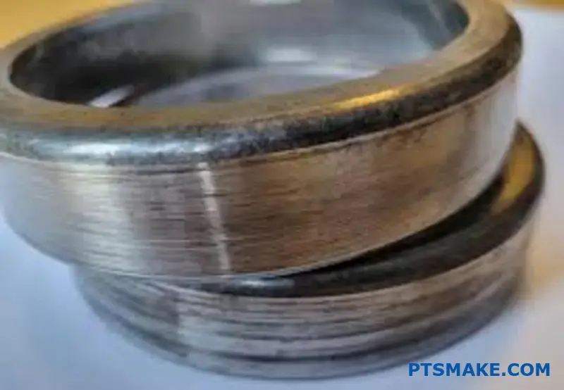
What is ‘creep’ in the context of bearing fits?
Imagine a car wheel that’s not bolted on tightly. As the car moves, the wheel might slowly rotate on the hub. That’s the basic idea behind bearing creep.
Understanding the Phenomenon
Creep is the slow, continuous rotation of a bearing ring relative to its mounting surface. This happens when the fit is too loose. The ring essentially "walks" around the shaft or inside its housing under load. This highlights the importance of correct bearing fit tolerance.
Key Effects of Creep
This seemingly small movement has big consequences. It can severely impact the performance and lifespan of your assembly.
| Consequence | Description |
|---|---|
| Fretting Corrosion | Reddish-brown abrasive debris forms between surfaces. |
| Accelerated Wear | Mating surfaces are damaged, altering critical dimensions. |
| Premature Failure | The bearing and its seat fail much sooner than expected. |
The Mechanics Driving Creep
Creep is most common when a stationary ring experiences a rotating load. The load slightly deforms the shaft or housing at the point of contact.
If the fit is loose, this deformation creates a tiny wave of material ahead of the load zone. This wave causes the ring to slip incrementally with each revolution. Over time, these tiny slips add up, causing the entire ring to slowly rotate, or "creep."
From Creep to Catastrophic Failure
This constant micromovement is destructive. It wears away the surfaces, creating fine metallic particles. These particles instantly oxidize in the air, forming a hard, abrasive powder.
This process is known as fretting corrosion7. This abrasive paste grinds away at both the bearing and its seat, destroying the precision of the fit. We always emphasize this point in our projects at PTSMAKE, as prevention is far cheaper than a cure.
The damage compounds itself. As material is worn away, the fit becomes even looser, which accelerates the creep and wear process until the component fails.
| Fit Type | Result of Rotating Load | Risk Level |
|---|---|---|
| Loose Fit | Ring slips and rotates (creep) | High |
| Correct Interference Fit | Ring is securely held in place | Low |
| Excessively Tight Fit | Internal stress, overheating | High |
Bearing creep is the slow rotation of a loosely fitted ring, which causes wear and fretting corrosion. This damage compromises the assembly’s integrity, leading to premature failure. Achieving the correct bearing fit tolerance is crucial for preventing this destructive cycle.
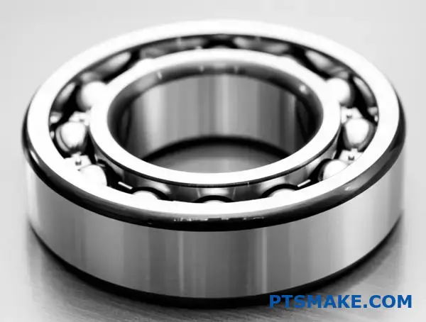
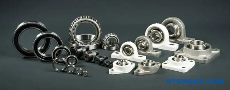
How do different bearing types influence fit selection?
Not all bearings are created equal. Their internal design directly impacts the fit you need. This is a critical detail in precision engineering.
Ball bearings, for instance, often use lighter fits. They are ideal for high speeds and moderate loads.
Roller bearings, however, are built for heavier tasks. They require tighter interference fits to handle the increased stress.
Let’s look at a quick comparison:
| Bearing Type | Typical Load | Fit Requirement |
|---|---|---|
| Ball Bearing | Light to Moderate | Lighter Interference |
| Roller Bearing | Heavy | Tighter Interference |
Understanding these differences is key. It ensures longevity and optimal performance for your assembly.
Deep Dive into Bearing Specifics
The geometry of a bearing’s rolling elements is the main factor. It dictates how loads are distributed. This directly influences the required fit. A proper bearing fit tolerance is non-negotiable for performance.
Load Capacity and Fit Selection
Cylindrical roller bearings are designed for heavy radial loads. This requires a strong interference fit. The fit prevents the inner ring from creeping or slipping on the shaft under load.
Spherical roller bearings can handle heavy loads and misalignment. Their fits must be tight enough to prevent slippage. But they also need to accommodate angular movement without binding.
Tapered roller bearings handle combined radial and axial loads. The fit selection here is more complex. It often involves adjusting for a specific axial runout8 or preload condition to ensure proper contact angles and load distribution. In our work at PTSMAKE, we often machine housings to extremely tight tolerances for these applications.
Precision and Bearing Type
High-precision applications, like in robotics or aerospace, often use angular contact ball bearings. These demand very precise and often light interference fits to maintain their accuracy.
| Bearing Type | Load Type | Precision Need | Common Fit |
|---|---|---|---|
| Cylindrical Roller | Heavy Radial | Moderate to High | Tight Interference |
| Spherical Roller | Heavy Radial + Misalignment | Moderate | Firm Interference |
| Tapered Roller | Combined Radial & Axial | High | Varies (Preload) |
| Angular Contact Ball | Combined (in pairs) | Very High | Light Interference |
Choosing the right bearing is only half the battle. The fit selection, dictated by the bearing type’s load capacity and precision, is what truly ensures your design functions reliably and efficiently. Tighter fits for heavy loads, precise fits for high accuracy.
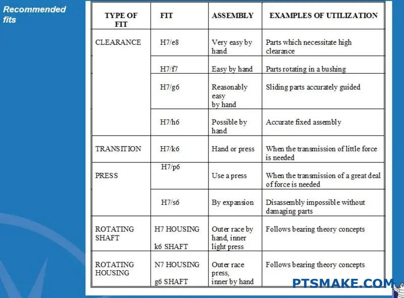
What are the main categories of fit selection factors?
To select the right fit, I always run through a mental checklist. This simple process ensures no critical factor is overlooked. It’s a systematic way to guarantee the reliability and performance of any assembly.
This checklist covers the essential variables. Each one plays a key role in the final decision. Ignoring even one can lead to issues down the line.
Here are the core factors to consider:
| Factor Category | Key Considerations |
|---|---|
| Operational Loads | Type (radial, axial, combined) and magnitude |
| Rotational Speed | High speed vs. low speed operations |
| Thermal Conditions | Operating temperature range |
| Component Materials | Shaft and housing material properties |
| Precision Needs | Required running accuracy and tolerance |
| Maintenance | Ease of assembly and disassembly |
Key Factors in Your Fit Selection Checklist
Drilling down into this checklist reveals the interconnected nature of these factors. You can’t just consider one in isolation.
Load and Speed Dynamics
The type and magnitude of the load are critical. A heavy radial load on a rotating ring typically requires a tight interference fit. This prevents the ring from creeping or spinning in its seat.
High speeds introduce centrifugal forces. These can loosen an interference fit on a shaft. You must account for this to maintain the proper mounting.
Environmental and Material Influences
Temperature is a major player. Components heat up during operation, causing materials to expand. This is especially important when the shaft and housing are different materials, leading to differential thermal expansion9.
For example, a steel bearing in an aluminum housing will have different expansion rates. We must calculate the fit for the operating temperature, not just room temperature.
| Load Condition | Rotating Ring | Recommended Fit |
|---|---|---|
| Light / Variable | Inner Ring | Transition / Loose |
| Normal / Heavy | Inner Ring | Interference |
| Normal / Heavy | Outer Ring | Interference |
Precision and Assembly Requirements
Finally, consider the required precision and assembly process. High-precision applications need a specific bearing fit tolerance to minimize runout.
Also, think about maintenance. If a component needs frequent disassembly, a very tight interference fit might not be practical. A transition fit could be a better compromise.
This mental checklist provides a structured framework. Considering load, speed, temperature, materials, precision, and assembly is crucial. It helps avoid premature failure and ensures component longevity.
An interference fit directly reduces a bearing’s internal clearance. This relationship is critical for proper function.
When you press-fit a bearing, the tight fit forces the rings to change shape. The inner ring expands slightly. The outer ring compresses a little.
This change reduces the initial Radial Internal Clearance (RIC). You must account for this reduction. If you don’t, you risk damaging the bearing before it even starts working.
| Fit Type | Action | Effect on Clearance |
|---|---|---|
| Interference | Press-fitting ring | Reduces Internal Clearance |
| Clearance | Slip-fitting ring | No effect on Clearance |
The Critical Calculation for Longevity
Ignoring the clearance reduction caused by an interference fit is a common mistake. It leads to a condition called preloading. Preload puts internal stress on the bearing’s rolling elements.
This happens because the reduction in clearance can be greater than the initial clearance itself. The result is a negative operating clearance.
Consequences of Unplanned Preload
Preloading dramatically increases friction and heat generation. This causes the lubricant to break down faster. Ultimately, it leads to premature bearing failure. The bearing’s service life can be cut significantly.
This change happens because of the material’s elastic deformation10 under pressure.
Selecting the Right Clearance
To prevent this, you must choose an initial bearing clearance that accommodates the fit. Bearings are available in different classes (like C3 or C4) with larger initial clearances. A proper Bearing fit tolerance is key.
At PTSMAKE, we always factor in the fit when helping clients select components. We analyze the design to ensure the final operating clearance is correct.
| Initial Clearance | Interference Fit | Operating Condition |
|---|---|---|
| Standard (CN) | Tight | Potential Preload |
| Increased (C3) | Tight | Correct Operating Clearance |
| Too Large (C4) | Loose | Excessive Play / Vibration |
An interference fit always reduces a bearing’s initial internal clearance. This reduction must be calculated and accounted for by selecting a bearing with sufficient initial clearance. Overlooking this step leads to preloading, increased friction, and premature failure of the assembly.
What is the relationship between tolerance grade and manufacturing cost?
The link between tolerance grade and manufacturing cost is direct and significant. Tighter tolerances always mean higher costs.
This isn’t a simple, straight line. The cost increases exponentially as you demand more precision.
The Cost-Tolerance Curve
Moving from a standard tolerance grade like IT7 to a high-precision one like IT5 can dramatically increase the part’s price. It’s a critical decision.
You must justify this choice with clear functional requirements. Does the application truly need it?
| Tolerance Grade | Relative Cost Factor (Approx.) | Typical Application |
|---|---|---|
| IT10 | 1x | General assembly |
| IT7 | 2x – 4x | Standard fits |
| IT5 | 5x – 10x | Precision bearings |
Tighter tolerances, such as moving from IT7 to IT5, require a complete shift in the manufacturing approach. This is where the costs begin to multiply rapidly. Every step becomes more complex and time-consuming.
At PTSMAKE, we guide clients through this decision to balance performance and budget.
Why Tighter Tolerances Cost More
Several factors contribute to the exponential cost increase. It’s not just about running a machine for longer.
Advanced Manufacturing Processes
Achieving a grade like IT5 often requires more than standard CNC machining. It may involve secondary processes like grinding or lapping. These steps add significant time and require specialized equipment.
Slower Machining and More Passes
To hold tight tolerances, machines must run at slower speeds and take lighter cuts. This increases cycle time per part. For instance, a critical coordinate measuring machines11 is essential for verification.
Higher Scrap and Inspection Rates
The acceptable margin for error is much smaller. This leads to a higher scrap rate, as more parts may fall outside the specification. Every finished part also requires more intensive inspection, often with advanced metrology equipment, adding to labor costs. A tight bearing fit tolerance is one area where this is unavoidable.
| Factor | IT7 Requirement | IT5 Requirement |
|---|---|---|
| Process | Standard CNC Milling/Turning | Precision Grinding/Lapping |
| Inspection | Calipers, Micrometers | CMM, Optical Comparators |
| Scrap Rate | Low | Potentially High |
| Cycle Time | Standard | Significantly Increased |
Choosing a tighter tolerance grade like IT5 over IT7 drastically increases costs due to specialized machinery, longer cycle times, and more rigorous inspection. Always justify such precision with a clear application need to avoid unnecessary expenses and ensure project viability.
How do thin-walled housings affect fit choices?
Standard interference fits are often too aggressive for thin-walled housings. These delicate structures lack the rigidity to withstand the high pressure from a standard press fit.
This can lead to distortion. Instead of a secure, uniform grip, you get a warped housing. This compromises the entire assembly’s performance and reliability.
The Challenge of Standard Fits
When you press a bearing into a thin housing using a standard interference fit, the housing wall is forced outward. It simply can’t resist the radial pressure. This is a common issue we address in our projects at PTSMAKE.
| Housing Type | Standard Interference Fit Effect | Recommended Action |
|---|---|---|
| Standard Wall | Secure, uniform grip | Proceed with standard fit |
| Thin-Walled | Distortion, non-uniform contact | Use lighter fits |
The Risks of Distortion and Non-Uniform Contact
When a thin housing distorts, it often becomes oval-shaped. This means the bearing is only making contact at a few high-pressure points, rather than around its entire circumference.
This non-uniform contact is a serious problem. It creates stress concentrations that can lead to premature bearing failure or housing cracks. The overall assembly loses its intended precision.
At PTSMAKE, we guide our clients to select a proper bearing fit tolerance to avoid this. The goal is to provide enough grip to prevent slippage without creating excessive hoop stress12 that deforms the part.
Lighter fits are essential. These reduce the radial forces exerted on the housing. Sometimes, using retaining compounds or alternative mounting methods is a better solution. This ensures the assembly remains stable and performs as designed.
Key Risks of Improper Fits in Thin Housings
| Risk | Description | Consequence |
|---|---|---|
| Distortion | Housing wall deforms under pressure. | Loss of roundness and precision. |
| Stress Points | Uneven contact creates high-pressure spots. | Premature component failure. |
| Bearing Damage | Non-uniform load on the bearing. | Reduced operational life. |
| Loose Fit | Bearing can slip or spin in the housing. | Wear and loss of function. |
Using standard interference fits on thin-walled housings causes distortion and non-uniform contact. This compromises the assembly’s integrity. Lighter fits or alternative mounting methods are required to prevent stress concentrations and ensure reliability.
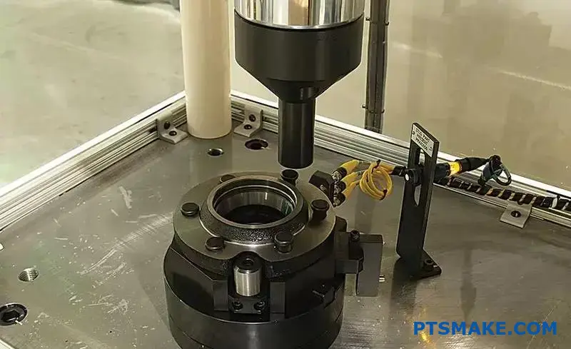
What is the correct procedure for mounting interference bearings?
Mounting interference fit bearings correctly is critical. This process ensures a long service life and optimal machine performance. The two primary safe methods are thermal expansion and mechanical pressing.
Heating expands the bearing, allowing it to slide on easily. Pressing uses controlled force for the installation. Both methods are effective when done right. Choosing the correct one is key to preventing damage.
Here is a quick overview:
| Method | Best For | Key Consideration |
|---|---|---|
| Bearing Heater | Medium to Large Bearings | Precise Temperature Control |
| Arbor/Hydraulic Press | Small to Medium Bearings | Proper Tooling & Alignment |
Each approach demands specific tools and techniques for success.
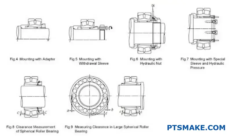
The Thermal Method: Induction Heaters
Induction heaters are a modern, safe, and efficient method. They heat the bearing’s inner ring uniformly and quickly. This controlled expansion allows it to slip onto the shaft without force, minimizing internal stress.
This is much safer than old methods like oil baths or open flames. You must monitor the temperature carefully. Overheating can permanently alter the steel’s properties and ruin the bearing. A good rule is to never exceed 120°C (250°F).
The Mechanical Method: Presses
For smaller bearings, a hydraulic or arbor press works well. This method requires absolute precision. You must use a mounting sleeve that makes full contact with the face of the ring being mounted.
For a shaft mount, apply pressure only to the inner ring. For a housing mount, press only the outer ring. Applying force to the wrong ring transmits it through the rolling elements. This can cause Brinelling13 and lead to premature failure.
Proper alignment is also crucial. This ensures the bearing goes on straight. The correct Bearing fit tolerance determines the force required.
| Feature | Induction Heating | Hydraulic/Arbor Press |
|---|---|---|
| Principle | Thermal expansion | Mechanical force |
| Control | High (temperature) | Moderate (pressure) |
| Risk | Overheating, contamination | Misalignment, brinelling |
| Speed | Fast for larger bearings | Fast for smaller bearings |
| Tooling | Heater unit | Press, mounting sleeves |
In summary, both induction heating and mechanical pressing are reliable. Success hinges on choosing the right method, using proper tooling, and paying close attention to details like temperature or pressure to avoid costly bearing damage.
How to select a fit for a high-precision spindle application?
Selecting the right fit is a delicate balancing act. For high-precision spindles, you need a tight fit. This provides the rigidity and accuracy required.
However, going too tight creates problems. It can cause excessive preload and generate too much heat. This compromises the entire system.
The Core Challenge
Finding the sweet spot is key. It ensures the spindle performs reliably and accurately over its entire lifespan. This is a common challenge we solve with our clients at PTSMAKE.
| Fit Type | Advantage | Disadvantage |
|---|---|---|
| Tight Fit | High rigidity, better accuracy | Excessive preload, heat generation |
| Looser Fit | Lower preload, less heat | Potential vibration, reduced accuracy |
Understanding the Consequences
Getting the balance wrong has serious implications. The choice directly impacts performance, component life, and the quality of the machined parts. It’s a decision that requires careful consideration of operating conditions.
The Risk of Excessive Preload
A fit that is too tight increases the internal load on the bearing elements. This raises friction, which in turn generates significant heat.
As the spindle heats up, thermal expansion can tighten the fit even further. This vicious cycle drastically reduces bearing life. It also increases the Hertzian contact stress14 between the rolling elements and raceways, leading to premature failure.
The Danger of an Insufficient Fit
Conversely, a fit that is too loose is also detrimental. It allows for micro-movements between the bearing and its housing or shaft.
This leads to fretting corrosion, vibration, and chatter during operation. The result is poor surface finishes and a loss of dimensional accuracy on the workpiece.
Finding the Optimal Zone
The ideal bearing fit tolerance isn’t a single value. It depends on several factors. Our experience shows that speed, load, and temperature must be analyzed to find the optimal fit.
| Operating Factor | Influence on Fit Selection |
|---|---|
| High Speed | Leans towards a looser fit to manage heat |
| Heavy Loads | Leans towards a tighter fit for rigidity |
| High Temperature | Leans towards a looser fit to account for expansion |
Choosing the correct fit involves a deep understanding of the application’s unique demands.
Selecting the right spindle fit is a critical trade-off. A tight fit is needed for rigidity and precision, but it risks excessive preload and heat, which shortens bearing life. The goal is achieving the optimal balance for peak performance and durability.
Unlock Precision: Request Your PTSMAKE Bearing Fit Tolerance Quotation Now!
Take your manufacturing to the next level with PTSMAKE! If Bearing fit tolerance challenges are slowing you down, request a quote today and experience unparalleled quality, rapid lead times, and expert CNC/injection molding support. Let’s engineer solutions that exceed your toughest precision standards—contact PTSMAKE now!

Discover how this electrochemical wear occurs and strategies to mitigate it. ↩
Understand how materials temporarily change shape under stress, a key principle behind effective interference fits. ↩
Understand how this surface wear occurs and the precision required to prevent it. ↩
Learn how this critical bearing dimension is affected by temperature and fit selection. ↩
Learn about this common failure mode and how proper interference fits prevent it. ↩
Understand how these microscopic peaks, or asperities, dictate friction, wear, and lubrication in mechanical assemblies. ↩
Dive deeper into this wear mechanism and discover how to effectively counteract it in your mechanical assemblies. ↩
Understand how this crucial measurement impacts the accuracy and performance of rotating systems. ↩
Learn how temperature affects material dimensions and influences your critical fit selection. ↩
Explore how material stress and strain principles apply to component fits in precision assemblies. ↩
Learn how CMMs provide the micron-level accuracy required for verifying tight tolerances. ↩
Understand the key force that causes distortion in thin-walled housings. ↩
Understand what Brinelling is and how improper mounting techniques can cause this permanent bearing damage. ↩
Understand how preload affects bearing surfaces and longevity. ↩