Designing gears seems straightforward until you face the reality of interdependent parameters. A single change in module affects diameter, strength, and cost. Adjust the pressure angle, and you’re trading tooth strength for smooth operation.
Gear parameters are the dimensional and geometric specifications that define a gear’s size, shape, and performance characteristics. These include module, number of teeth, pressure angle, pitch diameter, and face width, which together determine how gears mesh, transmit power, and fit within mechanical systems.
Mastering these parameters means understanding their relationships and trade-offs. I’ll walk you through each parameter’s practical purpose, show you how they interact, and share the decision-making frameworks that help you optimize gear designs for your specific applications.
What is the fundamental role of the module (or diametral pitch)?
The module is the foundational unit of a gear’s size. Think of it as the gear’s DNA. It directly defines the size of the gear teeth.
This single value is crucial. A larger module means larger, stronger teeth. A smaller module results in finer, more precise teeth.
Why Module Comes First
In any new gear design, the module is the starting point. It dictates the gear’s overall proportions and strength. Many clients ask, "what are the parameters of a gear" (Gear Parameters). I always tell them to start here.
| Module (m) | Tooth Characteristic | Application Example |
|---|---|---|
| 1 | Fine | Small robotics, printers |
| 3 | Medium | Automotive transmission |
| 5 | Coarse | Heavy machinery |
This initial choice balances the need for power transmission with the required precision for the application. It sets the stage for all other calculations.
The Module as a Universal Standard
The module isn’t just a number. It’s a system that standardizes gear manufacturing. It simplifies the entire design and meshing process.
Two gears with the same module will mesh perfectly. This is true even if they have a different number of teeth. This interoperability is fundamental to mechanical design.
This standardization is a core principle we follow at PTSMAKE. It ensures the components we machine for different clients can work together seamlessly.
Metric Module vs. Imperial Diametral Pitch
While the metric system uses the module, the imperial system uses Diametral Pitch (DP). They serve the same purpose but are inversely related.
The module is the pitch diameter divided by the number of teeth. A larger module number means a larger tooth. The number of teeth and module determine the gear’s pitch circle diameter1.
Diametral Pitch is the number of teeth per inch of pitch diameter. A larger DP number means a smaller tooth. It can be confusing, but the goal is the same: to standardize tooth size for proper meshing.
| System | Key Parameter | Relationship to Tooth Size |
|---|---|---|
| Metric | Module (m) | Larger m = Larger tooth |
| Imperial | Diametral Pitch (DP) | Larger DP = Smaller tooth |
Understanding both is essential for global manufacturing projects. It ensures we meet exact specifications, whether from a European or American client.
The module, or diametral pitch, is the fundamental parameter in gear design. It establishes tooth size, dictates overall gear dimensions, and ensures compatibility between meshing gears, making it the first and most critical design decision.
What does the number of teeth (z) physically represent?
The number of teeth (z) is more than just a count. It is a fundamental design parameter. Together with the module (m), it directly defines a gear’s physical size.
Specifically, these two values determine the pitch circle diameter (d). The formula is simple: d = m × z. This means a gear’s size isn’t arbitrary. It’s a direct result of these core specifications. This relationship is crucial for gear design.
| Number of Teeth (z) | Module (m) | Pitch Circle Diameter (d) |
|---|---|---|
| 20 | 2 | 40 mm |
| 40 | 2 | 80 mm |
| 20 | 3 | 60 mm |
This table shows how changing either the number of teeth or the module affects the gear’s overall diameter.
The Primary Role in Defining Gear Ratio
The most critical function of the tooth count is setting the gear ratio. This ratio is the relationship between the number of teeth on two meshing gears. It dictates the output speed and torque of a gear system.
For example, if a driving gear with 20 teeth (z1) meshes with a driven gear of 40 teeth (z2), the gear ratio is 2:1. The output speed will be halved, but the torque will be doubled. This principle is fundamental to mechanical power transmission.
In our work at PTSMAKE, we frequently help clients select the right gear parameters to achieve precise motion control in robotics and automation projects.
Impact on Transmission Smoothness
The number of teeth also significantly impacts how smoothly a gear operates. Generally, more teeth lead to a smoother and quieter transmission.
This happens because a higher tooth count increases the meshing engagement2 between gears. With more teeth in contact at any given moment, the load is distributed more evenly. This reduces vibration and noise.
Small vs. Large Tooth Count
- Fewer, larger teeth: Can handle higher loads but may produce more noise and vibration.
- More, smaller teeth: Offer smoother, quieter operation but may have a lower load capacity per tooth.
Choosing the right tooth count involves balancing strength, speed, torque, and operational smoothness for the specific application.
The number of teeth, combined with the module, sets the gear’s size. It is the primary factor in determining the gear ratio, which controls speed and torque. It also influences the smoothness and noise level of the gear’s operation.
What is the pressure angle (α) and its primary function?
The pressure angle (α) is a key factor in gear design. It defines the angle of force transmission between meshing gear teeth. This angle directly impacts the gear’s performance and strength.
Understanding what gear parameters matter is vital. The pressure angle is one of the most important. Most modern gears use a 20° standard. This offers a great balance between strength and efficiency.
The Core Trade-Off
A gear’s pressure angle creates a fundamental trade-off. It’s a balance between bending strength and contact stress on the teeth.
| Pressure Angle | Bending Strength | Contact Stress & Bearing Load |
|---|---|---|
| Lower (e.g., 14.5°) | Weaker Tooth Base | Lower |
| Higher (e.g., 20°, 25°) | Stronger Tooth Base | Higher |
Choosing the right angle is crucial for the gear’s intended application and lifespan.
Deeper Dive: Standards and Consequences
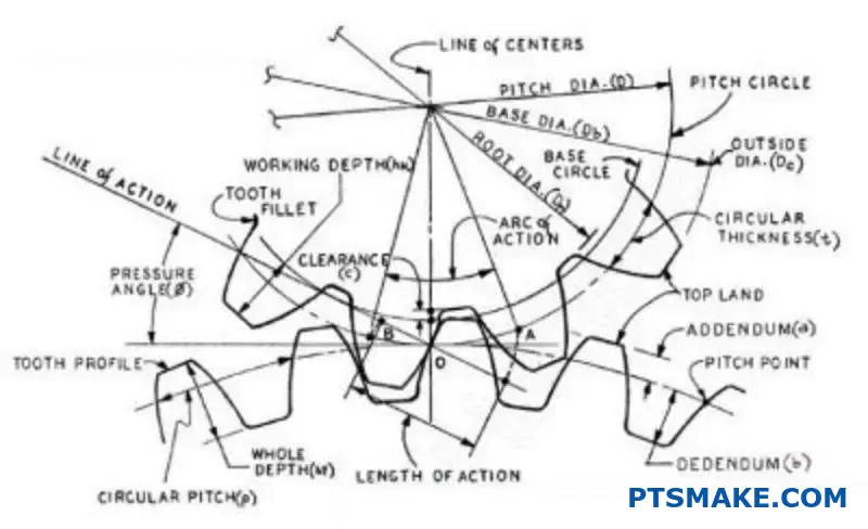
The pressure angle is the angle between the line of force and a line tangent to the pitch circle. The force itself is transmitted along the line of action3.
Historically, 14.5° was a common standard. However, it produced teeth that were prone to undercutting. This weakens the base of the tooth.
To solve this, the industry largely shifted to a 20° pressure angle. At PTSMAKE, we typically recommend 20° for most applications. It provides a wider, stronger tooth base, improving load capacity.
There is also a 25° standard. It offers even greater tooth strength. However, it comes with downsides. It increases the radial force on the bearings, which can lead to higher wear and more operational noise.
Choosing the correct angle requires careful engineering analysis. We help clients weigh these factors to optimize their designs. It is not just a number, it defines how the system behaves.
Comparing Common Pressure Angles
| Angle | Pros | Cons |
|---|---|---|
| 14.5° | Smoother, quieter operation; less bearing load. | Weaker tooth; prone to undercutting. |
| 20° | Good balance of strength and efficiency; industry standard. | Standard choice, few specific cons. |
| 25° | Strongest tooth profile; high load capacity. | Higher bearing loads; can be noisier. |
The pressure angle dictates force transmission between gear teeth. The common 20° standard balances tooth strength against bearing load and contact stress. Higher angles increase strength but also increase stress and potential noise, creating a critical design trade-off.
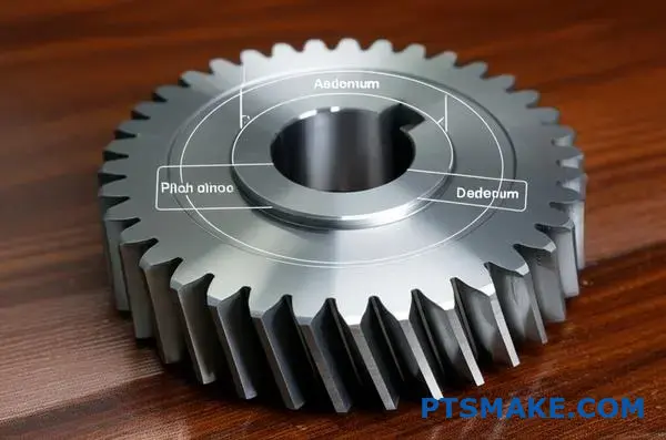
Addendum and Dedendum as Radial Dimensions
The addendum and dedendum are key radial dimensions. They are measured from the pitch circle. One goes up, the other goes down.
Together, they define the full height of a gear tooth. This is crucial for how gears fit and work together.
The Tooth Above the Pitch Circle
The addendum is the height from the pitch circle to the top of the tooth. It determines how far a tooth extends.
The Tooth Below the Pitch Circle
The dedendum is the depth from the pitch circle to the tooth’s root. It defines the space for the mating gear’s tooth tip.
| Dimension | Location | Function |
|---|---|---|
| Addendum | Above Pitch Circle | Defines tooth tip height |
| Dedendum | Below Pitch Circle | Defines tooth root depth |
These measurements are not random. They directly control the working depth of the gear mesh.
Understanding how these dimensions work is fundamental. They dictate whether gears engage smoothly or fail prematurely. These radial dimensions are critical gear parameters (Gear Parameters).
The addendum of one gear must mesh correctly with the dedendum of its mate. This interaction space is called the working depth. It’s the depth of engagement between two gears.
A small gap, known as clearance, is left at the bottom of the tooth space. This prevents the top of one tooth from hitting the bottom of the mating tooth space. Proper clearance is essential.
In past projects at PTSMAKE, we’ve seen designs where these values were off by tiny amounts. This seemingly small error can cause major problems. These issues include excessive noise, vibration, and rapid wear. It can even lead to complete system failure.
Improper dimensions can cause interference4, where the teeth physically collide instead of rolling smoothly.
This is why precision is non-negotiable in gear manufacturing.
Engagement Scenarios
| Scenario | Addendum/Dedendum Relationship | Result |
|---|---|---|
| Correct | Properly calculated | Smooth, efficient power transmission |
| Too Large | Excessive working depth | Bottoming out, high stress |
| Too Small | Insufficient engagement | Slipping, backlash, low contact |
At PTSMAKE, we use advanced CNC machining to hold extremely tight tolerances on these features. We ensure every gear we produce meets exact design specifications for reliable performance. This precision prevents engagement problems.
Addendum and dedendum are radial measurements from the pitch circle. They define the tooth’s height and root depth. These dimensions are critical for determining the working depth and ensuring smooth, reliable gear engagement, preventing operational failure.
What is the purpose of backlash in a gear system?
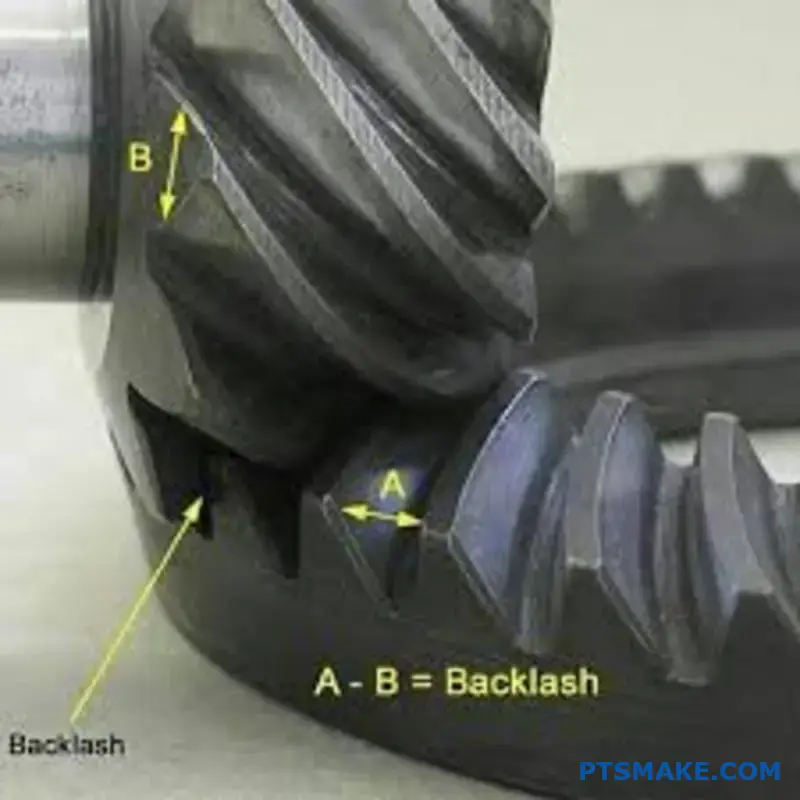
Backlash is the clearance or gap between mating teeth of two gears. It’s often seen as a flaw, but it’s an essential design feature.
This gap ensures gears don’t jam. It provides space for lubrication to form a protective film between the teeth. This prevents direct metal-to-metal contact.
Why Clearance is Necessary
Without backlash, several problems can arise. Thermal expansion is a major one. As gears operate, they heat up and expand. The clearance gives them room to grow.
Manufacturing tolerances also play a role. Understanding all the factors, including key data like Gear Parameters, is vital for proper design.
| Factor | Reason for Backlash |
|---|---|
| Thermal Expansion | Allows gears to expand with heat without binding. |
| Manufacturing Tolerance | Accounts for tiny variations in gear dimensions. |
| Lubrication | Ensures a fluid film can form between teeth. |
The Trade-Off: Precision vs. Performance
The main challenge with backlash is finding the right balance. It involves a direct trade-off with positional accuracy. More backlash means less precision. This can be an issue in robotics or CNC machines.
In these applications, any "slop" in the gear train reduces accuracy. The system might not respond instantly to changes in direction.
Finding the Sweet Spot
However, zero backlash isn’t always the goal. Too little clearance can be just as bad as too much. Insufficient backlash can lead to premature wear and high stress. It also increases friction and heat generation.
This can cause what is known as Meshing Interference5, where the teeth bind instead of rolling smoothly. In past projects at PTSMAKE, we’ve found the ideal backlash depends entirely on the application’s specific requirements.
| Backlash Level | Positional Accuracy | Risk of Jamming |
|---|---|---|
| High | Low | Low |
| Optimal | High | Low |
| Low / Zero | Very High | High |
We work closely with clients to define these needs. We ensure the manufactured gears have the optimal backlash for both longevity and precision.
Backlash is an intentional gap between gear teeth. It’s crucial for preventing jamming caused by heat and manufacturing variations. The key is balancing this necessary clearance with the required level of positional accuracy for the specific application.
What is the pitch circle diameter (d) and why is it crucial?
The pitch circle is an imaginary circle on a gear. It’s the theoretical line where two gears roll together without any slipping. Think of it as two perfect cylinders rolling against each other.
This concept is the foundation of gear design. It’s the primary reference for nearly all other gear dimensions. Without it, calculations would be incredibly complex. All essential gear parameters are derived from this single feature.
| Parameter Derived from PCD | Function |
|---|---|
| Module | Defines tooth size |
| Center Distance | Sets spacing between gears |
| Addendum/Dedendum | Determines tooth height |
| Tooth Thickness | Affects strength and backlash |
The Theoretical Heart of Gear Engagement
The pitch circle isn’t a physical part of the gear. You can’t touch it. It’s a purely theoretical concept that simplifies the complex interactions between meshing gear teeth into a pure rolling motion. This idealization is vital for initial design and calculation.
In our projects at PTSMAKE, we always start here. This imaginary circle dictates the gear’s speed ratio and its exact placement relative to its mating gear. It’s the starting point for a successful design.
From Ideal Concept to Physical Reality
While we imagine pure rolling at the pitch circle, real gear teeth experience both rolling and sliding. This combination is necessary for smooth power transfer. The specific shape of the gear tooth, often an involute profile6, is designed to manage this motion. It ensures a constant angular velocity, even with the sliding. Understanding which gear parameters are critical is the first step.
The Key to Center Distance
The pitch circle diameter directly determines the center distance between two meshing gears. The formula is simple yet powerful:
Center Distance (C) = (PCD of Gear 1 + PCD of Gear 2) / 2
This calculation is fundamental. An incorrect center distance leads to improper meshing, causing excessive noise, wear, and potential failure.
| Gear 1 PCD (mm) | Gear 2 PCD (mm) | Required Center Distance (mm) |
|---|---|---|
| 50 | 100 | 75 |
| 60 | 60 | 60 |
| 40 | 80 | 60 |
The pitch circle is an imaginary yet fundamental reference line in gear design. It simplifies complex tooth interactions into a pure rolling motion, serving as the basis for calculating all other critical dimensions and the crucial center distance between gears.
What is the center distance (a) in a gear pair?
The center distance, denoted by ‘a’, is a fundamental parameter. It’s simply the distance between the centers of two mating gears.
This dimension is not just a number. It dictates the entire physical layout of a gearbox. It determines how and where the gears sit.
Getting this distance right is critical. It ensures smooth power transmission. Incorrect spacing leads to operational problems.
| Component | Description |
|---|---|
| Gear 1 Center | The rotational axis of the first gear. |
| Gear 2 Center | The rotational axis of the second gear. |
| Center Distance (a) | The direct line distance between these two centers. |
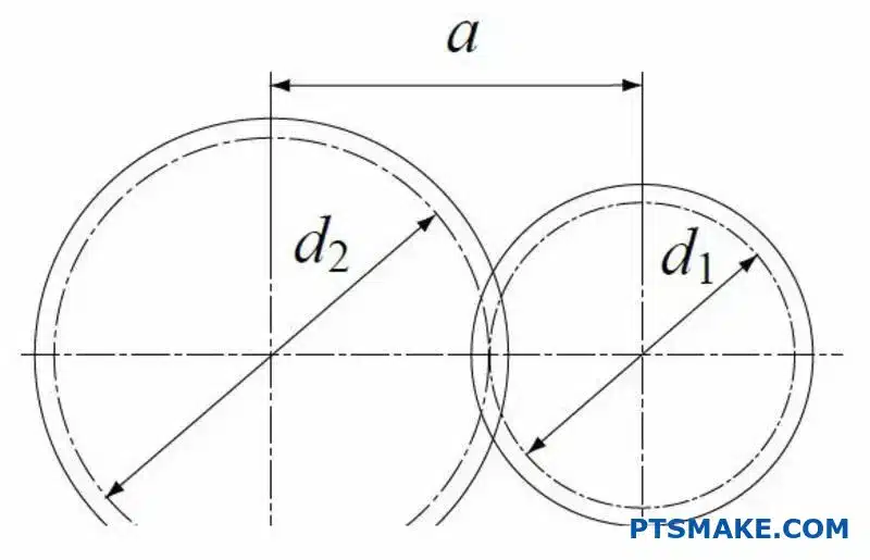
Calculating the center distance is straightforward. It is half the sum of the two gears’ pitch diameters7. This direct relationship is crucial for design.
The standard formula is simple:
a = (d1 + d2) / 2
Here, d1 and d2 represent the diameters of the two gears. This calculation is a starting point for any gearbox design.
We can also express this using the module (m) and the number of teeth (z).
a = m * (z1 + z2) / 2
This shows how key gear parameters are linked. When clients ask "Gear Parameters" (what are the parameters of a gear?), we often start here. We explain how module, teeth, and center distance are connected.
In projects we handle at PTSMAKE, the center distance is a critical dimension. When we CNC machine a gearbox housing, this value dictates the exact locations for the bearing bores.
Any deviation causes problems. Too large a distance creates excess backlash and noise. Too small a distance causes jamming and rapid wear. The precision of the housing directly impacts gear performance.
| Factor | Consequence of Incorrect Center Distance |
|---|---|
| Too Large | Increased backlash, noise, potential tooth skipping. |
| Too Small | Gear jamming, excessive wear, high friction. |
The entire system’s physical layout depends on this value. It influences the casing size, bearing placement, and the final assembly process.
The center distance is the space between two gear axes. It’s calculated from the pitch diameters. This measurement is the foundation for the gearbox layout and ensures the gears mesh correctly and efficiently.
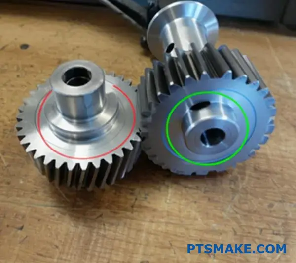
What defines the face width (b) of a gear?
Face width, denoted as ‘b’, is a critical gear parameter. It seems simple but has a huge impact. It’s the length of the tooth parallel to the gear’s axis.
Think of it as the thickness of the gear from front to back. A wider face means more material.
Why Face Width Matters
This dimension directly relates to strength. It determines how much torque a gear can handle. It also affects how load is spread across the tooth surface. Understanding gear parameters like this is fundamental.
| Feature | Narrow Face Width | Wide Face Width |
|---|---|---|
| Torque Capacity | Lower | Higher |
| Load Distribution | More Concentrated | More Spread Out |
| Material Cost | Lower | Higher |
A wider gear is generally stronger. But it’s not always better. The optimal width depends on the specific application.

Torque Capacity and Load Distribution
A gear’s primary job is transmitting torque. The face width is central to this task. A wider face provides a larger contact area for meshing teeth. This allows the gear to handle higher loads without failing. It’s a straightforward relationship.
This larger area also improves load distribution. Instead of concentrating force on a small point, the load is spread across the tooth’s length. This significantly reduces the stress on the material. A wider face effectively lowers the Hertzian contact stress8 on the tooth surface.
The Trade-Offs of a Wider Face
However, a wider face width isn’t a universal solution. It introduces challenges. The most significant is alignment sensitivity. If wide gears are not perfectly aligned, the load will concentrate on one edge. This causes uneven wear and can lead to premature failure.
At PTSMAKE, our CNC machining ensures perfect alignment. We help clients find the right balance. It’s about maximizing strength without compromising reliability due to manufacturing constraints.
| Design Factor | Impact of Increasing Face Width |
|---|---|
| Torque Transmission | Increases capacity |
| Bending Strength | Increases |
| Alignment Sensitivity | Increases risk of edge loading |
| Manufacturing Cost | Increases due to more material |
Face width (b) is the length of the gear tooth. It is directly linked to a gear’s torque capacity and load distribution. A wider face increases strength but demands more precise alignment, a key consideration in high-performance applications.
What is profile shift (or addendum modification)?
Profile shift is a key gear design technique. It involves intentionally moving the cutting tool. This displacement is relative to the gear blank’s center.
This adjustment is not random. It is a calculated modification. We call the amount of shift the "profile shift coefficient (x)."
Its main purpose is solving specific design problems. We use it to avoid undercut on small gears. It also helps adjust the center distance between two gears.
Clients often ask, "Gear Parameters?" (What are the parameters of a gear?). Profile shift is a crucial one that directly impacts performance.
| Purpose | Description |
|---|---|
| Avoid Undercut | Prevents weakening of the tooth base on gears with few teeth. |
| Adjust Center Distance | Allows for non-standard center distances without changing gear size. |
This deliberate displacement of the cutting tool is what defines profile shift. A positive coefficient (x > 0) means we move the tool away from the gear’s center. This results in a thicker, stronger tooth root. It is the primary method to prevent undercut on pinions with a low tooth count.
Conversely, a negative coefficient (x < 0) moves the tool closer to the center. This creates a thinner tooth. We typically use a negative shift on the larger gear in a pair. This is done to achieve a specific, often reduced, center distance.
In my experience at PTSMAKE, balancing these shifts is crucial. A positive shift can strengthen the tooth. But too much can lead to pointed tooth tips and increased sliding friction. It affects the gear’s involute profile9.
The choice of coefficient is a precise calculation. It directly impacts the gear’s strength, wear life, and operational noise. It’s a trade-off we carefully manage for every project.
| Shift Type | Tool Position | Primary Effect |
|---|---|---|
| Positive (+x) | Moved away from center | Stronger tooth root, avoids undercut |
| Zero (x=0) | Standard position | Standard gear tooth profile |
| Negative (-x) | Moved toward center | Thinner tooth, reduces center distance |
Profile shift is a strategic displacement of the gear cutting tool. It serves two main goals. It prevents tooth undercut in small pinions for greater strength. It also allows for flexibility in adjusting the gear set’s center distance.
What is the root fillet radius (ρf) and its significance?
The root fillet is the curved transition at the base of a gear tooth. It is a critical design feature. Its main job is to reduce stress concentration at the tooth root.
The Role of the Root Fillet
Think of it as a smooth corner instead of a sharp one. This curve distributes forces more evenly. This prevents cracks from forming. When customers ask about key gear parameters (Gear Parameters), the root fillet is always a top consideration for durability.
| Feature | Stress Level | Fatigue Life |
|---|---|---|
| Sharp Corner | High | Low |
| Rounded Fillet | Low | High |
A properly designed fillet is crucial for preventing tooth bending fatigue failure. It significantly extends the gear’s operational life.
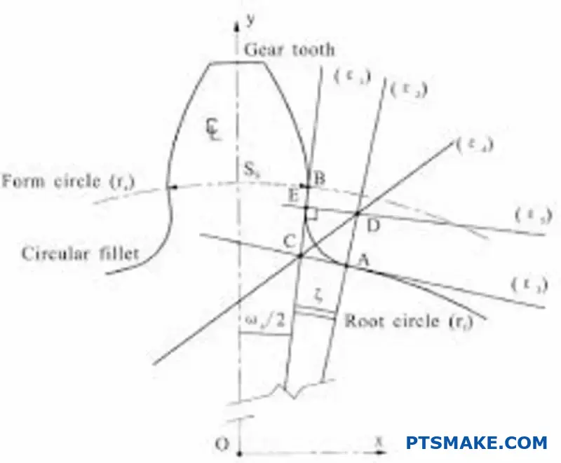
Preventing Bending Fatigue Failure
The tooth root is the most vulnerable area. It experiences the highest bending stress during operation. Without a fillet, this stress becomes highly concentrated at the sharp corner. This is a primary cause of fatigue failure.
A larger fillet radius generally means lower stress. However, there’s a limit. If the radius is too large, it can interfere with the mating gear tooth. This causes a problem called trochoidal interference. Finding the optimal radius is a balancing act.
In our work at PTSMAKE, we often use Finite Element Analysis (FEA). This helps us simulate and find the perfect fillet radius. It maximizes strength without causing interference. This careful analysis reduces the stress concentration10 at the root.
Fillet Radius vs. Stress
The relationship is clear. A larger, smoother fillet is better for durability. Based on our tests, the impact is significant.
| Fillet Radius (ρf) | Relative Stress Concentration |
|---|---|
| Small (Sharp) | 2.5x |
| Medium | 1.8x |
| Optimal (Large) | 1.2x |
This shows why precise control over the root fillet radius during CNC machining is so important. It directly impacts the gear’s reliability and performance.
The root fillet is not just a small curve. It’s a critical design element that reduces stress concentration at the tooth’s base. This directly prevents fatigue failure and ensures the long-term reliability of the gear system.
How do spur, helical, and bevel gear parameters fundamentally differ?
While all gears share core parameters like module and pitch diameter, the fundamental differences emerge from their geometry. Each type adds unique parameters to suit its specific function.
Spur gears are the simplest. Helical and bevel gears introduce crucial angular dimensions. These additions are not optional; they define how the gears work.
Understanding what are the parameters of gears (Gear Parameters) for each type is key. It dictates their application and performance.
| Gear Type | Key Unique Parameter | Purpose |
|---|---|---|
| Spur Gear | None (Straight Teeth) | Parallel Shaft Power Transmission |
| Helical Gear | Helix Angle (β) | Smoother, quieter operation |
| Bevel Gear | Cone Angles (Pitch, Root) | Angled Shaft Power Transmission |
Let’s explore why these specific parameters are necessary. Spur gears have straight teeth parallel to the gear’s axis. Their parameter set is the baseline for all gear types. It’s straightforward and effective for parallel shafts.
Helical gears introduce the helix angle (β). This angle is the reason for their smoother and quieter operation. The angled teeth engage gradually across their face, not all at once. This reduces shock and noise. This angle also introduces an axial thrust11 component, which is a key consideration in bearing selection.
Bevel gears are designed for intersecting shafts, typically at 90 degrees. Their cone angles are essential. These angles define the conical shape of the gear blank. Without the correct pitch cone angle, the teeth wouldn’t mesh properly. They would bind or have excessive backlash. At PTSMAKE, we always emphasize that these angles must be calculated precisely for the system to function correctly.
| Parameter | Why It’s Necessary | Impact on Design |
|---|---|---|
| Helix Angle (β) | Enables gradual tooth engagement. | Creates smoother power transfer but also axial load. |
| Cone Angles | Allows meshing of gears on intersecting axes. | Defines the fundamental shape for angled transmission. |
In short, spur gears rely on basic parameters. Helical gears add the helix angle for smoothness, while bevel gears use cone angles to transmit power between intersecting shafts. These unique parameters are dictated by their core geometry and intended application.
What is the relationship between module, teeth number, and diameter?
In gear design, module, teeth number, and diameter are not separate choices. They are a team. A change to one directly impacts the others. This relationship is governed by a fundamental formula.
Understanding this core principle is essential. It prevents costly errors and ensures your gears mesh perfectly. It’s the foundation of all gear calculations.
Let’s explore this simple but powerful connection.
The relationship boils down to one straightforward formula. It is the key to unlocking gear design and a core part of understanding Gear Parameters (what are the parameters of a gear).
The Core Formula
The fundamental equation is:
Pitch Diameter (d) = Module (m) × Number of Teeth (Z)
This formula shows a direct link. If you know any two values, you can always find the third. It’s that simple. This calculation gives us the Pitch Diameter12, a vital measurement for gear functionality.
How They Influence Each Other
Let’s see this in action. Imagine we have a fixed module of 2. Changing the number of teeth directly changes the diameter.
| Module (m) | Number of Teeth (Z) | Pitch Diameter (d) |
|---|---|---|
| 2 | 20 | 40 mm |
| 2 | 40 | 80 mm |
| 2 | 60 | 120 mm |
As you can see, doubling the teeth doubles the diameter.
Now, what if we need a specific diameter, say 100 mm? We can achieve this with different combinations of module and teeth.
| Target Diameter (d) | Module (m) | Number of Teeth (Z) |
|---|---|---|
| 100 mm | 2 | 50 |
| 100 mm | 4 | 25 |
| 100 mm | 5 | 20 |
At PTSMAKE, we use this principle daily to engineer solutions that fit precise spatial and strength requirements for our clients.
The relationship is clear: module, number of teeth, and pitch diameter are intrinsically linked. You cannot alter one of these core parameters without affecting at least one of the others. This is a non-negotiable rule in mechanical design.
How does the pressure angle affect tooth strength and contact ratio?
Choosing the right pressure angle is a critical balancing act in gear design. It’s a fundamental decision that directly trades tooth strength for smooth operation.
Understanding the Trade-Off
A larger pressure angle, like 25°, creates a wider and more robust tooth base. This enhances strength and load-carrying capacity.
Conversely, a smaller angle, such as 14.5°, results in a higher contact ratio. This means more teeth are engaged at once, leading to smoother, quieter power transmission. Your choice depends entirely on the application’s demands. Considering questions like Gear Parameters (what are the parameters of gears) is key here.
| Pressure Angle | Primary Advantage | Primary Disadvantage |
|---|---|---|
| Larger (e.g., 25°) | Higher Tooth Strength | Lower Contact Ratio (Noisier) |
| Smaller (e.g., 14.5°) | Higher Contact Ratio (Smoother) | Lower Tooth Strength |
This core trade-off influences many aspects of gear performance.

Larger vs. Smaller Angles: A Deeper Look
In our projects at PTSMAKE, the pressure angle is one of the first parameters we confirm with clients. The implications are significant for manufacturing and final performance.
The Strength of a 25° Angle
A larger pressure angle creates a tooth with a thick, strong base. This geometry is excellent for applications involving high torque and heavy loads. It significantly reduces stress at the tooth root.
This design is also less susceptible to undercutting13 during manufacturing. This is where the cutting tool removes material from the base of the gear tooth, weakening it.
The Smoothness of a 14.5° Angle
While not as strong, a smaller pressure angle offers superior smoothness. With a higher contact ratio, the load is distributed over more teeth simultaneously.
This results in less vibration and quieter operation. It is often the preferred choice for precision instruments and applications where low noise is a critical requirement. The teeth are, however, thinner and more prone to bending under stress.
| Characteristic | Larger Pressure Angle (25°) | Smaller Pressure Angle (14.5°) |
|---|---|---|
| Tooth Base | Wide and Strong | Narrow and Weaker |
| Operation | Can be noisier | Quiet and Smooth |
| Best Use Case | High-load industrial machinery | Precision instruments, low-noise systems |
Choosing a pressure angle is a crucial design trade-off. You must balance the need for tooth strength and high load capacity against the requirement for smooth, quiet operation. The final decision always rests on the specific needs of your application.
What is the concept of a ‘standard gear’ versus a ‘modified gear’?
Gears can be categorized into two main types. These are standard gears and modified gears. This distinction is crucial in design and manufacturing.
Standard gears adhere to internationally recognized parameters. This includes a standard pressure angle and zero profile shift. They are the baseline for gear design.
Modified gears, however, deviate from these standards. We make these changes for specific reasons. This ensures the gear system works perfectly in its unique application.
Key Differences at a Glance
| Feature | Standard Gear | Modified Gear |
|---|---|---|
| Design Basis | Follows established standards | Deviates for specific needs |
| Profile Shift | Zero | Positive or Negative |
| Center Distance | Standard | Can be non-standard |
| Application | General-purpose | Optimized for performance |
Why We Modify Gears
You might wonder why we would change a perfectly good standard design. The reality is that real-world applications often present unique challenges. Standard gears are a great starting point, but not always the final solution.
Accommodating Non-Standard Center Distances
One of the most common reasons for modification is a non-standard center distance. Machine housings or existing components often dictate the distance between two gear shafts.
If this distance doesn’t match a standard gear pair, we must adjust. We use a profile shift14 to ensure the gears mesh correctly without backlash or binding. This is a frequent adjustment in our work at PTSMAKE.
Optimizing Performance
Modification is also a powerful tool for performance tuning. By adjusting specific parameters, we can enhance a gear’s characteristics. When customers ask about Gear Parameters (what are the parameters of a gear) that can be tuned, we often discuss these modifications.
Here are some common optimization goals we encounter:
| Optimization Goal | Modification Method | Benefit |
|---|---|---|
| Increase Strength | Positive profile shift | Prevents undercut, thickens tooth root |
| Reduce Noise | Adjust contact ratio | Ensures smoother, quieter operation |
| Improve Wear Life | Balance specific sliding | Distributes load more evenly |
| Avoid Interference | Tip relief adjustments | Prevents tooth tip collision |
These tailored changes transform a standard component into a high-performance part, perfectly suited for its specific task.
In short, standard gears are based on universal specifications. Modified gears are custom-tailored solutions. They address practical constraints like non-standard spacing or the need for enhanced strength, quieter operation, and longer service life in specific applications.
How do helical gear parameters (helix angle) impact axial thrust?
The helix angle in a gear is a classic engineering trade-off. It’s the very feature that gives helical gears their smooth, quiet operation.
However, this angled engagement creates a side effect. It generates an axial thrust force along the gear’s shaft. This force must be managed correctly.
Without proper support, this thrust can cause significant problems in your assembly. It’s a critical factor to consider in design.
| Parameter | Positive Effect | Negative Effect |
|---|---|---|
| Helix Angle | Smoother, Quieter Operation | Generates Axial Thrust |
This cause-and-effect relationship is central to helical gear design. We need to account for both sides of the equation.
The Origin of Axial Thrust
When helical gear teeth mesh, the force isn’t applied perpendicularly to the shaft’s axis like in spur gears. The angle of the teeth splits the total resultant force15 into two main components.
One is the tangential force, which transmits the torque. The other is the axial force, or thrust, which pushes the gear sideways along its shaft. A larger helix angle means a larger axial thrust component.
Managing Axial Thrust with Bearings
This axial load must be supported to prevent gear misalignment and failure. This is where bearings become critical.
You can’t just use standard radial bearings. You need bearings designed to handle axial loads, such as:
- Tapered roller bearings
- Angular contact ball bearings
- Dedicated thrust bearings
In our projects at PTSMAKE, selecting the right bearing system is a key part of the design consultation. It adds complexity and cost, but it’s non-negotiable for reliability.
The Herringbone Gear Solution
There’s a clever design that eliminates this problem: the herringbone gear. Think of it as two helical gears—one right-handed and one left-handed—joined together.
The opposing helix angles generate equal and opposite axial thrust forces. These forces cancel each other out internally within the gear.
| Feature | Helical Gear | Herringbone Gear |
|---|---|---|
| Axial Thrust | Present | Self-Canceling |
| Bearing Needs | Thrust Bearings Required | Simpler Bearings OK |
| Manufacturing | Simpler | More complex & costly |
This elegant solution simplifies the bearing requirements but makes the gear itself more challenging to manufacture.
The helix angle’s benefit of smooth operation comes at the cost of creating axial thrust. This force requires management by specific bearings, adding complexity. Herringbone gears provide an integrated solution by canceling this thrust internally.
What is the contact ratio and which parameters influence it?
The contact ratio is a critical gear parameter. It tells you the average number of teeth in contact at any moment. Think of it as a measure of engagement overlap.
For smooth, continuous power transmission, this number must always be greater than one. Several design choices influence this crucial ratio. Understanding what these parameters of a gear are is key.
Key Factors Influencing Contact Ratio
Below are the primary factors we consider in our designs at PTSMAKE. Each one can be adjusted to achieve the desired performance for our clients.
| Parameter | General Effect on Contact Ratio |
|---|---|
| Pressure Angle | A smaller angle usually increases it. |
| Addendum | A larger addendum increases it. |
| Profile Shift | A positive shift often increases it. |
A higher contact ratio is almost always better. We aim for a value above 1.2 in most applications. Why? Because it ensures that a new pair of teeth engages before the previous pair disengages.
This overlap is the secret to smooth and quiet gear operation. It eliminates moments of single-tooth contact, which can cause torque fluctuations, vibration, and noise. It distributes the load over more teeth.
Pressure Angle’s Role
A smaller pressure angle, like 14.5°, creates a longer line of contact compared to a 20° angle. This longer path directly boosts the contact ratio, promoting smoother meshing. However, it can result in a weaker tooth base.
Addendum and Profile Shift
Increasing the addendum (the height of the tooth above the pitch circle) extends the tooth tip. This physically lengthens the length of the path of contact16. A positive profile shift achieves a similar effect, moving the tooth profile outward.
In past projects at PTSMAKE, we’ve carefully balanced these parameters. We optimize for a high contact ratio while maintaining tooth strength and avoiding interference.
| Contact Ratio | Performance Characteristic |
|---|---|
| < 1.0 | Unacceptable; intermittent contact |
| 1.0 – 1.2 | Acceptable, but may have some noise |
| > 1.2 | Desirable; smooth and quiet operation |
| > 2.0 | High-performance; very smooth (helical) |
The contact ratio is a key metric for gear performance. It defines the smoothness of operation. It is directly influenced by design parameters like pressure angle, addendum, and profile shift. A ratio greater than 1.2 is ideal for minimizing noise and vibration.
How are worm gear parameters (lead, lead angle) unique?
When clients ask "what are the gear parameters?", they usually think of spur or helical gears. But worm gears have a unique language. Their key parameters are lead and lead angle, not pitch.
These two features define everything. They determine the gear’s high reduction ratio and its specific motion. Understanding them is crucial for proper design.
Spur Gear vs. Worm Gear Parameters
Here is a quick comparison:
| Parameter Type | Spur/Helical Gear | Worm Gear |
|---|---|---|
| Primary Metric | Pitch (Diametral/Module) | Lead |
| Angle Metric | Pressure Angle | Lead Angle |
| Ratio Driver | Tooth Count Ratio | Lead & Starts |
This difference is why worm drives achieve ratios of 50:1 or more, something impossible for a single spur gear pair.
Deep Dive into Lead and Lead Angle
Unlike spur gears that primarily roll, worm gears operate with a unique sliding action. This is where lead and lead angle become so important. At PTSMAKE, we focus heavily on these parameters during the design phase.
What is Lead?
Lead is the axial distance the worm thread advances in one full revolution. It’s not the same as pitch.
You can calculate lead with this simple formula:
Lead = Axial Pitch × Number of Starts
A worm can have multiple threads, or "starts." More starts mean a larger lead and a lower gear ratio.
The Role of the Lead Angle
The lead angle is the angle between the helix of the worm thread and a plane perpendicular to the worm’s axis.
A small lead angle (typically under 10 degrees) results in a high gear ratio. This geometry also increases friction and the potential for self-locking. This motion creates significant sliding velocity17, which influences efficiency and material choice.
Defining High Ratios
The unique combination of a small lead and a single-start worm creates massive speed reduction. The gear ratio isn’t just about tooth count; it’s a function of the worm’s geometry.
| Worm Starts | Lead Angle | Typical Ratio Range |
|---|---|---|
| Single | Low | 40:1 to 100:1+ |
| Double | Medium | 20:1 to 50:1 |
| Multiple | High | 5:1 to 30:1 |
As you can see, the number of starts directly impacts the lead angle and the resulting gear ratio.
Lead and lead angle are the defining parameters of worm gears. They replace the concept of pitch used in spur gears and are directly responsible for the high reduction ratios and unique sliding motion characteristic of worm drives.
What is the interplay between face width and load-carrying capacity?
At first glance, the logic seems simple. A wider gear face width should carry more load. This is generally true. It provides a larger contact area for teeth to engage.
However, this is not the complete picture. The relationship is more complex. A wider face width introduces new challenges that can impact gear performance and lifespan.
The Double-Edged Sword
A wider face increases the theoretical load capacity. But it also makes the gear system much more sensitive to any misalignment. Even slight errors can cause major problems.
| Aspect | Wider Face Width | Narrower Face Width |
|---|---|---|
| Load Capacity | Higher | Lower |
| Misalignment | More sensitive | Less sensitive |
| Load Distribution | Prone to unevenness | More uniform |
| Manufacturing | Tighter tolerances needed | More forgiving |
This sensitivity can negate the benefits of a wider design.
The Critical Role of Alignment
Perfect alignment is rare in real-world applications. Shaft deflection, bearing wear, and housing tolerances all contribute to minor misalignments.
With a wide face width, these small errors cause the load to concentrate on one edge of the tooth. This creates intense pressure points instead of distributing the load evenly across the face. This uneven load concentration18 leads to premature wear, pitting, and even tooth breakage.
Finding the Balance: Face Width to Diameter Ratio
To manage this trade-off, engineers use the face width to diameter ratio. This ratio provides a guideline for designing stable and reliable gears. When clients ask us ‘Gear Parameters determine performance?’, this ratio is a key part of our discussion.
At PTSMAKE, we work with clients to find the optimal balance. Our precision machining ensures that alignment and profile accuracy are maintained, maximizing the benefits of the chosen face width.
A common rule of thumb is to keep this ratio within a certain range to ensure good load distribution.
| Gear Type | Typical Ratio (Face Width / Pitch Diameter) |
|---|---|
| Spur Gears | 0.8 to 1.2 |
| Helical Gears | Up to 2.0 |
| Bevel Gears | ~0.3 (of cone distance) |
Adhering to these guidelines helps prevent the negative effects of misalignment.
A wider face width can boost load capacity, but it demands higher precision. It increases sensitivity to misalignment, which can lead to uneven load distribution and early failure. The face width to diameter ratio is a crucial design guideline for balance.
How does profile shift interact with center distance and backlash?
Profile shift is more than just a theoretical concept. It is a powerful tool we use in practical gear design. It directly links tooth geometry to the final assembly.
This adjustment allows us to solve real-world engineering problems. We can modify how gears fit and perform together.
The Core Relationship
A key application is adjusting the center distance. A positive total shift pushes the gears further apart. A negative total shift brings them closer. This principle is fundamental.
| Shift Type | Effect on Center Distance |
|---|---|
| Positive | Increases |
| Negative | Decreases |
| Zero | Standard |
This control is vital for custom applications.
In gear design, knowing what are the parameters of a gear is crucial. Profile shift is one of the most versatile of these parameters. It provides an elegant solution for non-standard mounting distances.
Adapting to Real-World Constraints
Imagine needing to fit gears into an existing housing. The mounting points are fixed and not at a standard distance. Here, profile shift is essential.
By applying a calculated positive or negative shift, we modify the gears. This allows them to mesh perfectly at that specific, non-standard distance. We often use this technique at PTSMAKE for replacement parts.
This method avoids redesigning entire assemblies. It saves time and significant cost for our clients.
Fine-Tuning Backlash
Profile shift is also my go-to method for controlling backlash. A positive shift increases the operational pitch diameter. This action naturally increases the space, or backlash, between meshing teeth.
Conversely, a negative shift reduces it. This precision is critical in applications requiring minimal play. The addendum modification coefficient19 is the factor we adjust to achieve this.
The relationship can be summarized as follows:
| Total Profile Shift | Center Distance | Backlash |
|---|---|---|
| Positive | Increases | Increases |
| Negative | Decreases | Decreases |
Based on our testing results, this fine-tuning capability is indispensable for high-precision systems. It ensures optimal performance and reduced wear over time.
Profile shift is a practical tool for adjusting gear assemblies. It directly modifies the center distance and allows for precise backlash control, solving common issues with non-standard mounting and performance requirements.
What is the system of gear accuracy grades (e.g., ISO, AGMA)?
Gear accuracy grades are a vital classification system. They categorize gears based on their manufacturing precision. This ensures consistent quality and performance across different batches.
These standards, such as ISO 1328 and AGMA 2015, are not arbitrary. They define specific allowable errors for critical gear parameters.
For example, they set limits on pitch deviation and profile error. The choice of grade is crucial. It’s determined by factors like operational speed and acceptable noise levels for the final application.
The core idea is simple. A lower grade number, like ISO 4 or AGMA Q13, means higher precision. A higher number, like ISO 12 or AGMA Q6, indicates a lower precision level.
This precision is measured against specific geometric tolerances. The standards provide detailed charts defining what are the parameters of a gear and their acceptable limits for each accuracy grade.
Here are some key parameters controlled by these standards:
| Parameter | Description | Impact on Performance |
|---|---|---|
| Pitch Deviation | The error in the distance between adjacent teeth. | Affects operational smoothness and noise levels. |
| Profile Error | The deviation from the ideal involute tooth shape. | Influences wear patterns and load distribution. |
| Helix Deviation | The error in the angle of the gear tooth trace. | Affects tooth contact and overall load capacity. |
| Runout | The eccentricity of the gear teeth relative to its axis. | Causes vibration and can lead to uneven wear. |
Choosing the right grade is a critical design decision. High-speed applications, like those in automotive transmissions or robotics, demand high-accuracy grades. This minimizes vibration, noise, and premature wear. A slight cumulative pitch deviation20 can cause significant issues at high RPMs.
In contrast, a low-speed, non-critical mechanism, such as a manual hand-crank, can function perfectly with a lower, more cost-effective grade. At PTSMAKE, we guide clients in selecting the optimal grade to balance performance requirements with their budget.
Gear accuracy grades classify manufacturing precision by setting tolerances for parameters like pitch and profile error. The right grade is determined by the application’s specific needs, primarily its operational speed, load, and noise constraints, ensuring optimal performance and cost-effectiveness.
How do you select the initial module for a new design?
Choosing the right initial module is a critical first step. It directly impacts the gear’s strength, size, and overall performance. A module that is too small will fail. One that is too large adds unnecessary weight and cost.
The core of the process is a balance. You must balance the required torque against the material’s strength. This initial calculation provides a solid foundation for your entire gear design. It helps avoid costly redesigns later.
A Practical Methodology
The process begins with key gear parameters: torque and material strength. These numbers are your starting point for everything else.
| Step | Action | Purpose |
|---|---|---|
| 1 | Define Torque | Know the maximum load the gear will handle. |
| 2 | Select Material | Choose based on strength, wear, and cost. |
| 3 | Calculate Stress | Determine the required tooth strength. |
| 4 | Standardize | Select the nearest standard module. |
This systematic approach ensures your gear can handle its job without failing.
Diving into the Calculation
A practical method starts with preliminary stress calculations. At PTSMAKE, we often begin with formulas like those from Lewis or AGMA. These help estimate the forces acting on a single gear tooth.
Bending Stress Analysis
First, we analyze bending stress. This calculation determines if a tooth will break off at its root under load. You use the torque and gear geometry as inputs. The result tells you the minimum size the tooth needs to be. This gives you a preliminary module value.
Contact Stress Analysis
Next, we look at surface durability. The force between meshing teeth can cause pitting or wear over time. The analysis of contact stress21 is crucial for gears that must last a long time. It ensures the tooth surface won’t deform or fail prematurely.
From Calculation to Standardization
These calculations give you a required module, like 2.37 mm. However, you cannot manufacture a custom 2.37 mm module easily. You must round up to the nearest standard value, such as 2.5 mm.
| Calculated Module | Standard Module Choice | Reason |
|---|---|---|
| 1.15 mm | 1.25 mm | Round up for safety margin. |
| 2.37 mm | 2.50 mm | Standard for manufacturability. |
| 3.89 mm | 4.00 mm | Ensures strength and availability. |
Choosing a standard module simplifies manufacturing and reduces costs. It ensures you can source cutting tools and inspection gauges easily. This is a key step in our design-for-manufacturability process.
To select an initial module, start with torque and material strength. Perform preliminary stress calculations to find a required module. Finally, round this value up to the nearest standard module to ensure manufacturability and reliability for your design.
How do you choose between a standard and a larger pressure angle?
Choosing your gear’s pressure angle feels like a major decision. But it’s simpler than you think. Most of the time, the standard 20° is the perfect choice. It offers a great balance of performance.
However, some designs need more. If you must maximize torque in a small space, a larger angle is better. This is a common challenge when considering all the gear parameters (Gear Parameters). Let’s look at a simple framework.
| Pressure Angle | Primary Use | Key Trade-off |
|---|---|---|
| 20° (Standard) | General applications | Balanced performance |
| 25° (Larger) | High torque, compact designs | Increased noise |
Think of 20° as your default setting. Only change it if you have a specific, compelling reason.
A Deeper Dive into the Decision
Let’s break down the "why" behind this choice. The pressure angle directly impacts the shape of the gear tooth. A larger pressure angle, like 25°, results in a wider, shorter tooth.
Stronger Teeth, Higher Capacity
This wider base makes the tooth inherently stronger. It can handle more force without breaking. This is why it’s ideal for applications demanding high torque transmission. In past projects at PTSMAKE, we’ve used 25° angles for heavy-duty robotic arms.
A larger angle also helps prevent a common issue. It reduces the risk of undercutting22 on gears with a low number of teeth, which can weaken the gear.
The Trade-Offs
But this strength comes at a cost. A larger pressure angle increases the radial load on the bearings. Your bearings must be robust enough to handle this extra force. It can also lead to a slightly lower contact ratio, which may result in more operational noise.
Here is a more detailed comparison:
| Feature | 20° Pressure Angle | 25° Pressure Angle |
|---|---|---|
| Torque Capacity | Good | Excellent |
| Tooth Strength | Standard | Higher |
| Bearing Load | Lower | Higher |
| Noise Level | Quieter | Potentially Noisier |
| Contact Ratio | Higher | Lower |
Your choice depends on which of these factors are most critical for your specific application.
In short, the 20° pressure angle is the industry standard for good reason. Opt for a larger 25° angle only when the need for higher torque capacity and tooth strength in a compact space outweighs the potential for increased noise and bearing loads.
How do you optimize gear parameters to reduce transmission noise?
Reducing gear noise is not about a single magic bullet. It’s about combining several gear parameters. Each one plays a part.
A successful low-noise design integrates these elements. It’s a holistic approach we often use at PTSMAKE for our clients.
High Contact Ratio
A higher contact ratio means more teeth are engaged at once. This distributes the load and smooths the transfer of power. We often achieve this with helical gears.
Accuracy Grade
Precision is non-negotiable for quiet operation. A higher accuracy grade, like ISO 5 or better, ensures teeth mesh perfectly. This reduces impacts and vibrations.
Tooth Profile Modifications
Even with high accuracy, modifications are key. Crowning and tip relief compensate for misalignments and deflections under load.
| Parameter | Primary Goal for Noise Reduction |
|---|---|
| Contact Ratio | Smooth power transfer, load distribution |
| Accuracy Grade | Minimize impact and vibration |
| Profile Modification | Compensate for real-world deflections |
A truly optimized gear set synergizes multiple parameters. Merely selecting a high accuracy grade isn’t enough. In past projects, we’ve seen highly precise gears fail noise tests. This happens when they don’t account for shaft deflection under load.
The Role of Tooth Modifications
This is where tooth profile modifications shine.
Crowning and Tip Relief
Crowning slightly curves the tooth face. This prevents the tooth edges from digging in when the shaft bends. Tip relief removes a tiny amount of material at the tooth tip. It eases the tooth into and out of mesh. These modifications are crucial for minimizing Transmission Error23.
Combining Parameters for Success
Our approach often involves using helical gears. They naturally have a high contact ratio. We then specify a high accuracy grade. Finally, we apply precise tooth profile modifications.
Based on our tests, this combination is incredibly effective. It ensures a smooth, continuous meshing action.
The table below shows a simplified comparison.
| Gear Type | Typical Contact Ratio | Noise Level | Common Modifications |
|---|---|---|---|
| Standard Spur | 1.2 – 1.6 | Moderate | Tip Relief |
| Helical | > 2.0 | Low | Crowning & Tip Relief |
This integrated strategy ensures gears run quietly. They are also more durable, as stress concentrations are minimized. This is a core principle in our CNC machining and molding services.
Achieving quiet gears requires a holistic approach. It’s about combining high contact ratios, precise manufacturing, and specific tooth modifications. These elements must work together to minimize vibrations at the source.
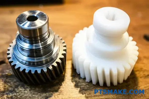
How do gear parameters change when designing for plastic vs. steel?
When you switch from steel to plastic for gear design, you can’t use the same blueprint. The material properties are fundamentally different. This requires significant changes to key gear parameters.
We must adjust the design to compensate for plastic’s lower strength and higher thermal expansion. Let’s explore the most critical changes.
Key Parameter Adjustments
Understanding which gear parameters to adjust is essential. The main ones are module, pressure angle, and backlash. Each plays a role in ensuring the gear performs reliably.
| Parameter | Steel Gear Design | Plastic Gear Design |
|---|---|---|
| Module | Typically Smaller | Needs to be Larger |
| Pressure Angle | Standard (e.g., 20°) | Often Larger (e.g., 25°) |
| Backlash | Tighter Tolerance | Requires More Clearance |
Why Plastic Gears Need Different Parameters
The core reason for these changes lies in the material’s physical properties. Plastic is not as strong or stable as steel.
Larger Module for Strength
Plastic has a much lower tensile strength than steel. To compensate, we increase the gear module. A larger module results in bigger, thicker teeth.
These larger teeth can handle more stress. They distribute the load over a wider area, preventing premature failure. This is a simple yet effective solution.
Larger Pressure Angle
A larger pressure angle, often 25° instead of the standard 20°, also helps. It creates a wider and stronger tooth base. This design reduces the risk of teeth bending or breaking under load. It’s a common adjustment we make at PTSMAKE for robust plastic gear systems.
Increased Backlash for Expansion
Plastics expand and contract significantly with temperature changes. They can also swell in humid environments due to hygroscopic expansion24. This dimensional instability is a major concern.
We design plastic gears with more backlash. This extra clearance ensures the gears don’t jam when they expand. Without it, the system would fail.
| Parameter Change | Reason for Plastic Gears |
|---|---|
| Larger Module | Compensates for lower material strength. |
| Larger Pressure Angle | Creates a wider, stronger tooth base. |
| Increased Backlash | Accommodates thermal and moisture expansion. |
Designing with plastic requires adjusting key gear parameters. A larger module and pressure angle add strength, while increased backlash prevents jamming from thermal or moisture expansion. These changes are crucial for a reliable gear system.
How do you create a personal checklist for reviewing gear design parameters?
A personal checklist is your best defense against costly errors. It transforms theory into a practical, repeatable process. This tool ensures you never overlook critical details.
Moving from CAD to a physical part requires systematic review. What gear parameters should you check first?
Fundamental Geometry
Start with the basics. These parameters define the gear’s shape and interaction. Confirm the number of teeth, module, and pressure angle.
Strength & Material
Next, verify strength. Ensure the chosen material and heat treatment can handle the expected torque and stress cycles. This prevents premature failure.
| Parameter Category | Key Items to Check |
|---|---|
| Geometry | Module, Pressure Angle, Number of Teeth |
| Strength | Material Selection, Hardness, Root Fillet |
Manufacturability Review
A perfect design is useless if it can’t be made. At PTSMAKE, we often see designs that are difficult or expensive to produce.
Your checklist must include a manufacturability gate. Can the tooth profile be cut with standard tools? Are there undercuts that require specialized processes? Simple adjustments here can significantly reduce costs.
Assembly and Application
Think about how the gear fits into the larger system. The center distance between mating gears is crucial. Also, consider the required backlash25 for proper operation.
Finally, review application-specific needs. Does the system require low noise? This might influence your choice of helix angle or surface finish. What is the target operational life? This affects material and lubrication choices.
A thorough checklist bridges design intent with real-world performance.
| Review Area | Key Considerations | Impact |
|---|---|---|
| Manufacturability | Undercuts, Tool Access, Tolerances | Production Cost & Lead Time |
| Assembly | Center Distance, Interference Checks | System Functionality & Fit |
| Application | Noise (NVH), Lifespan, Lubrication | End-Product Performance & Reliability |
A comprehensive checklist ensures that every critical parameter is reviewed. This methodical approach minimizes errors, streamlines production, and guarantees that the final gear performs exactly as intended in its application.
Unlock Gear Expertise with PTSMAKE—Your Precision Gear Partner
Need reliable, precision gear solutions tailored to your unique requirements? Contact PTSMAKE today for a competitive quote on CNC machined or injection molded gear components. Our team rapidly delivers high-quality, custom parts and expert advice—streamlining your project from prototype to production. Send us your RFQ now!

Discover how this imaginary circle forms the basis for all critical gear geometry calculations. ↩
Learn how gear teeth interact to ensure smooth, efficient power transmission in your designs. ↩
Explore this concept to better understand how force is transmitted between meshing gear teeth. ↩
Learn how this gear tooth collision can cause catastrophic failure and how to prevent it. ↩
See how this issue can cause system failure and learn the best practices for preventing it. ↩
Explore the geometric curve that ensures constant velocity and smooth power transmission in gearing. ↩
Discover why pitch diameters are the theoretical circles that define how gears roll together and transmit motion. ↩
Understand the principles of calculating stress at the point of contact between two curved bodies. ↩
Learn about the involute curve, the geometric basis for most modern gear teeth and how it’s affected by modifications. ↩
Explore how stress concentration impacts part durability and our methods to mitigate it. ↩
Discover how this force impacts bearing choice and overall system design. ↩
Click to understand this crucial gear dimension and its impact on your design’s performance. ↩
Discover how undercutting can weaken gear teeth and why preventing it is crucial in gear manufacturing. ↩
Learn the technical details of how this adjustment optimizes gear performance and strength. ↩
Discover how total force is broken down into components for better mechanical design analysis. ↩
Learn more about this crucial geometric factor that defines gear engagement duration. ↩
Discover how this factor influences efficiency, lubrication needs, and material choices in gear design. ↩
Learn how to calculate and mitigate the risks of high stress points on gear teeth. ↩
Explore how this key parameter redefines gear geometry and performance. ↩
Learn how this critical parameter affects gear train performance and positional accuracy. ↩
Understand how surface pressure between meshing gears impacts durability and operational life. ↩
Learn what undercutting is and how a larger pressure angle can effectively prevent it. ↩
Learn how this key metric quantifies gear meshing precision and its direct impact on noise. ↩
Learn how moisture absorption affects the size and performance of your plastic gears. ↩
Learn how this small gap impacts gear noise, wear, and overall system efficiency. ↩