Gear design failures cost manufacturing companies millions in downtime, repairs, and production losses every year. When a driven gear fails, it doesn’t just stop one machine—it can shut down entire production lines, delay critical deliveries, and damage your reputation with customers who depend on your reliability.
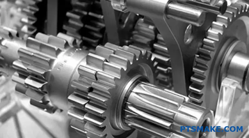
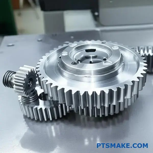
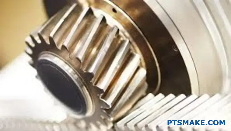
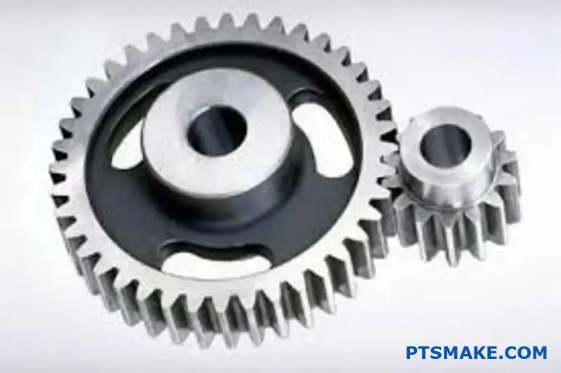
A driven gear is the follower component in a power transmission system that receives torque and motion from the driving gear, functioning as the output element that delivers the modified speed and torque characteristics to the downstream machinery or load.
I’ve worked with engineering teams who thought they understood gear design, only to face costly failures months later. This guide walks you through the essential principles, design considerations, and practical solutions that separate successful gear systems from expensive mistakes. You’ll discover the key factors that determine whether your driven gear performs reliably for years or fails when you need it most.
What fundamentally defines a gear as a ‘driven’ gear?
In any gear system, a gear’s role is not fixed. Its identity comes from its function within the power flow. The core idea is simple.
The Role of a Follower
A ‘driven’ gear is fundamentally a follower. It does not create motion. Instead, it receives torque and movement from another gear. This gear is called the driving gear. The driven gear’s action is purely reactive.
Consider the basic relationship between these two components.
| Gear Type | Function | Role in Energy Flow |
|---|---|---|
| Driving Gear | Initiates Motion | Active (Source) |
| Driven Gear | Receives Motion | Reactive (Follower) |
Its movement is a direct consequence of the driving gear’s input. It continues the transmission of power.
Tracing the Flow of Mechanical Power
To truly understand a driven gear, we must follow the energy. Power starts at a source, like a motor. This source turns the first gear, the driving gear. This gear holds the initial input energy.
The driving gear’s teeth mesh with the driven gear. This engagement transfers the energy. This process of torque transmission1 is the essence of how mechanical work is performed through a gear train. The driven gear now holds the power.
System Context is Everything
A gear’s label is not permanent. A gear that is driven in one context could be a driver in another. It completely depends on the overall machine design. Its role is relational.
At PTSMAKE, we often design complex gear trains. A single gear can receive motion from one gear and transmit it to another. It acts as both driven and driving simultaneously.
Here is how a gear’s role can shift.
| System Configuration | Gear A | Gear B | Gear C |
|---|---|---|---|
| System 1 | Driving | Driven | N/A |
| System 2 | Driving | Driven & Driving | Driven |
This shows that the position in the power chain defines the gear’s function.
A gear becomes ‘driven’ by its passive role in receiving power from a source gear. Its function is determined entirely by its position within the specific power transmission system, not by its physical characteristics.
What is the first principle of torque and speed transmission?
The core idea is simple: you can’t get something for nothing. This comes from the law of conservation of energy.
In a perfect mechanical system, the power you put in equals the power you get out. Power is a product of torque and speed.
So, if you increase torque, you must decrease speed. They have an inverse relationship. It’s a fundamental trade-off in all mechanical designs.
| Input | Output |
|---|---|
| High Speed | Low Speed |
| Low Torque | High Torque |
This principle is key to how we design gear systems.
The Role of the Gear Ratio
To control this trade-off, we use gears. The relationship between the input and output is defined by the gear ratio.
The formula is straightforward:
Gear Ratio = Number of Teeth on the Driven Gear / Number of Teeth on the Driver Gear
The driver gear provides the input power. The driven gear delivers the output.
Imagine a small 10-tooth gear driving a larger 40-tooth gear. The gear ratio is 40/10, or 4:1. This means the output speed will be one-fourth of the input speed. However, the output torque will be four times greater, minus any efficiency losses. This directly impacts the output angular velocity2 and torque.
In our work at PTSMAKE, we constantly apply this principle. We design custom gear sets for robotics and automotive parts. The goal is always to achieve the precise output needed.
Here’s a practical look at how ratios affect output:
| Driver Teeth | Driven Teeth | Gear Ratio | Speed Change | Torque Change |
|---|---|---|---|---|
| 20 | 60 | 3:1 | Reduced to 1/3 | Multiplied by 3 |
| 50 | 25 | 1:2 | Multiplied by 2 | Reduced to 1/2 |
Understanding this lets us engineer components that perform specific tasks reliably.
The law of conservation of energy dictates an inverse relationship between torque and speed. The gear ratio, determined by the tooth count of the driver and driven gear, is the mechanism we use to precisely control this trade-off in any mechanical system.
How does gear module dictate interchangeability and strength?
The gear module is a fundamental parameter in gear design. It directly influences how gears interact and perform. Understanding it is key to successful engineering.
What is a Gear Module?
Simply put, the module is the ratio of the gear’s pitch diameter to its number of teeth. It standardizes the gear tooth size.
The Rule for Interchangeability
For two gears to mesh correctly, they must have the same module. This ensures their teeth align perfectly, allowing for smooth power transmission. Different modules just won’t work together.
A larger module means a larger, more robust tooth. This allows the gear to handle greater loads without failing. It’s a direct indicator of strength.
| Feature | Low Module (e.g., M1) | High Module (e.g., M3) |
|---|---|---|
| Tooth Size | Small | Large |
| Strength | Lower | Higher |
| Precision | Higher | Lower |
| Application | Fine mechanics, robotics | Heavy machinery, automotive |
The Practical Side of Module Selection
Choosing the right module is a critical engineering decision. It’s a constant balancing act between strength, size, and precision. A larger module gives you a stronger tooth, but it also results in a larger, heavier, and often more expensive gear system.
Strength vs. Compactness
In applications where space is limited, like in aerospace or medical devices, a smaller module is often preferred. But you must ensure the teeth are strong enough for the required load.
Material choice becomes vital here. In past projects at PTSMAKE, we’ve used advanced polymers or hardened steels. This allows for smaller modules without sacrificing necessary strength.
Precision vs. Power
For high-precision systems, such as robotics or measuring instruments, a smaller module provides finer control and smoother operation. The smaller teeth allow for more precise angular adjustments.
Conversely, for high-torque applications like industrial gearboxes, a larger module is necessary. This ensures the teeth of the driving and Driven Gear can withstand high stress. The choice depends on the application’s core function. It’s about finding the right balance for the specific task. This calculation is based on the pitch diameter3, which dictates the effective contact point.
| Parameter | High Module Gear | Low Module Gear |
|---|---|---|
| Load Capacity | High | Low |
| Size & Weight | Larger / Heavier | Smaller / Lighter |
| Precision | Lower | Higher |
| Typical Use | Power Transmission | Motion Control |
Module dictates gear tooth size, which is crucial for meshing (interchangeability) and load capacity (strength). The right selection involves balancing power requirements against constraints like size and precision, a key decision in mechanical design.
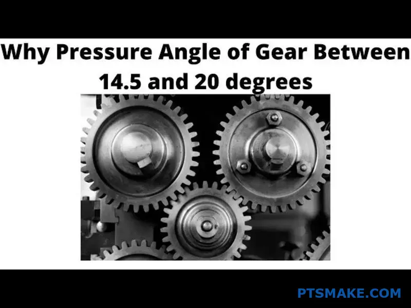
What is the pressure angle’s direct impact on practical performance?
The pressure angle dictates how force is transmitted between meshing gear teeth. Think of it as the direction of the push.
It’s a critical choice. The two most common standards are 20° and 14.5°. Each offers distinct performance trade-offs.
A larger angle generally means a stronger tooth. However, this comes at the cost of higher bearing loads. Your application determines the right balance.
| Pressure Angle | Primary Advantage | Primary Disadvantage |
|---|---|---|
| 20° | Higher Strength | Increased Bearing Load |
| 14.5° | Smoother Operation | Lower Strength |
The Engineering Trade-Offs in Detail
Choosing a pressure angle is a balancing act. There’s no single "best" option; it’s about what’s best for your specific design. At PTSMAKE, we guide clients through this decision daily.
Load Capacity vs. Bearing Loads
A 20° pressure angle creates a wider and stronger tooth base. This geometry allows the gear to handle significantly higher loads without failing. It’s the modern standard for most new designs for this reason.
The downside? That force is transmitted at a steeper angle. This increases the radial force pushing the gears apart, which in turn puts more stress on the shaft bearings.
Noise and Smoothness
The older 14.5° standard provides a smoother, more rolling contact between teeth. This results in quieter operation, which can be crucial for certain consumer electronics or medical devices.
The trade-off is a weaker tooth profile. It’s also more prone to undercutting4, a manufacturing defect. This is especially true when designing a pinion or driven gear with a low tooth count.
Comparing the Angles
Based on our testing and project data, the performance differences are clear.
| Feature | 20° Pressure Angle | 14.5° Pressure Angle |
|---|---|---|
| Load Capacity | High | Lower |
| Tooth Strength | Stronger, wider base | Weaker, narrower base |
| Bearing Load | Higher radial force | Lower radial force |
| Noise Level | Can be noisier | Quieter, smoother |
| Undercut Risk | Low | Higher |
The choice between a 20° and 14.5° pressure angle is a core engineering decision. It directly impacts load capacity, noise, and manufacturing feasibility. The 20° angle prioritizes strength, while the 14.5° angle favors smoother, quieter operation.
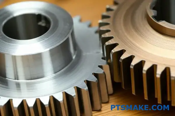
What distinguishes backlash from interference in a gear pair?
Backlash and interference are two critical concepts in gear design. They represent opposite ends of the spectrum for gear tooth spacing.
Simply put, backlash is an intentional gap. It is the clearance between the mating teeth of a gear pair.
Interference, however, is an unwanted overlap. It occurs when the tooth profiles of two gears clash instead of meshing smoothly. Understanding this difference is fundamental.
| Feature | Backlash | Interference |
|---|---|---|
| Definition | Intentional clearance | Unwanted overlap |
| Purpose | Allows lubrication | Undesirable by-product |
| Effect | Smooth operation | Binding and failure |
The Practical Implications of Each
Backlash isn’t a design flaw; it’s a necessity. This small gap is crucial for creating a space for lubrication. Without it, the lubricant would be forced out, leading to metal-on-metal contact.
This clearance also accommodates thermal expansion. As gears operate, they heat up and expand. Backlash provides the room needed for this growth, preventing the gears from seizing.
In contrast, interference is always destructive. It happens when the tooth profiles are not designed correctly. For example, the tip of one tooth might dig into the root of the mating tooth.
This clashing creates immense stress and friction. It causes binding, noise, and rapid wear. The smooth rolling action of the involute profile5 is disrupted. Ultimately, interference will lead to catastrophic failure of the gear set.
At PTSMAKE, we meticulously calculate tolerances. This ensures every gear, from the driver to the driven gear, has the optimal backlash. We prevent interference from ever becoming an issue in the final assembly.
| Condition | Primary Consequence | Long-Term Result |
|---|---|---|
| Sufficient Backlash | Smooth meshing, proper lubrication | Long service life, reliability |
| Interference | Binding, high friction, noise | Premature wear, component failure |
Backlash is the planned, essential gap between gear teeth that allows for lubrication and thermal expansion. Interference is the unplanned, damaging overlap of tooth profiles that leads to binding and system failure. One is by design, the other by error.
How does contact ratio define smooth power transmission?
Contact ratio is a simple yet powerful metric. It tells you the average number of gear teeth in contact at any moment. Think of it as a measure of engagement overlap.
For gears to work without interruption, this ratio must be greater than 1.0. This ensures the next tooth pair engages before the previous one leaves contact.
Higher ratios mean better performance.
Understanding Contact Ratio Values
A ratio above 1.0 is the foundation for smooth power transmission. It’s the difference between a rough, jerky motion and a continuous, steady flow of power.
| Contact Ratio | Meaning | Power Flow |
|---|---|---|
| < 1.0 | Intermittent Contact | Discontinuous |
| = 1.0 | Continuous (Theoretical) | Potentially Rough |
| > 1.0 | Overlapping Contact | Smooth |
A higher contact ratio directly improves the quality of gear operation.
Why Higher Is Better: The Role of Load Sharing
A contact ratio greater than 1.0 is essential for continuous power flow. If it were exactly 1.0, the entire load would shift instantly from one tooth to the next. This creates impact stress and vibration.
When the ratio is higher, say 1.6, it means two pairs of teeth are in contact 60% of the time. The load is shared between them. This sharing is fundamental to achieving smooth power transmission and ensuring proper conjugate action6.
This distribution reduces stress on each tooth. It also lowers the risk of failure and extends the gear’s service life. The entire system, especially the Driven Gear, operates more reliably.
Quieter and Smoother Operation
Load sharing doesn’t just improve durability; it also reduces noise. The gradual transfer of force between multiple teeth minimizes the "shock" of engagement. This results in a significantly quieter and smoother operation.
| Ratio Value | Load Distribution | Resulting Operation |
|---|---|---|
| ~1.2 | Minimal Overlap | Basic Continuity |
| 1.5 – 1.8 | Good Load Sharing | Smoother, Quieter |
| > 2.0 | Excellent Load Sharing | Very Smooth, Low Noise |
At PTSMAKE, we design gears with optimized contact ratios to meet specific application needs, balancing performance with manufacturing efficiency.
Contact ratio is the average number of teeth engaged at once. A ratio above 1.0 is non-negotiable for continuous power transfer. Higher ratios enhance smoothness and reduce noise by enabling multiple teeth to share the load, improving overall system reliability.
What are the functional roles of the addendum and dedendum?
The addendum and dedendum are fundamental to gear design. They define a tooth’s geometry. Think of them as height and depth from a baseline.
Their precise dimensions are critical. They ensure gears mesh correctly, transmit power smoothly, and last a long time.
The Addendum’s Role
The addendum is the tooth’s height. It extends from the pitch circle to the tooth tip. It directly engages with the mating gear.
The Dedendum’s Role
The dedendum is the tooth’s depth. It goes from the pitch circle to the tooth root. It creates necessary space.
| Feature | Addendum | Dedendum |
|---|---|---|
| Position | Above the pitch circle | Below the pitch circle |
| Function | Engages with the mating gear | Provides clearance for the mating tooth |
| Impact | Defines the contact surface | Prevents interference and wear |
How They Determine Working Depth
The addendum of two mating gears dictates the total working depth7. This is the effective depth of tooth engagement where power transmission occurs. Getting this right is non-negotiable for performance.
An incorrect working depth can lead to inefficient power transfer. In some of the projects we’ve handled at PTSMAKE, this has been the root cause of noise and vibration issues.
The Importance of Clearance
The dedendum is always slightly longer than the mating gear’s addendum. This difference creates a critical gap called "clearance."
Preventing Tooth Interference
This clearance ensures the tip of a gear tooth never hits the root of its mating tooth. Without this space, the gears would jam and fail quickly. This is especially important for a driven gear under high load.
This small detail prevents catastrophic failure. It highlights why precision in gear manufacturing is so essential. Our focus on tight tolerances ensures this clearance is always perfect.
| Aspect | Functional Purpose | Consequence of Error |
|---|---|---|
| Engagement | Smooth power transmission and load sharing | Noise, vibration, inefficiency |
| Clearance | Prevents tooth tip from hitting the root | Jamming, stress, wear |
| Lubrication | Allows lubricant to protect surfaces | Overheating, premature failure |
The addendum and dedendum are not just measurements. They define how gears interact. The addendum manages engagement and contact, while the dedendum creates the crucial clearance space to prevent interference and allow for lubrication. This balance is fundamental to gear functionality.
What are the key material properties for a driven gear?
Choosing the right material for a driven gear is a balancing act. You need performance, longevity, and cost-effectiveness. It’s not just about picking the strongest metal.
The right material must meet specific operational demands. Here are the core properties we always evaluate at PTSMAKE.
Key Performance Properties
High surface hardness is crucial. It directly fights wear and pitting from constant contact. Yet, the core must remain tough. This prevents teeth from snapping under sudden shock loads.
Longevity and Cost
Fatigue strength ensures the gear lasts through millions of cycles. Finally, good machinability is essential. It helps keep manufacturing costs reasonable, a factor we always consider for our clients.
| Property | Importance for Driven Gear |
|---|---|
| Surface Hardness | Resists wear and pitting |
| Core Toughness | Prevents tooth breakage |
| Fatigue Strength | Endures repeated loading cycles |
| Machinability | Impacts production cost |
A Deeper Look at Material Treatments
The perfect driven gear often has conflicting properties. It needs a very hard surface for wear resistance but a softer, tougher core to absorb impacts. This is rarely found in a base material.
This is why heat treatment is so important in gear manufacturing. Processes like case hardening8 create this ideal combination. They modify the surface of the steel, making it incredibly hard while the core remains ductile.
Carburized Steel vs. Through-Hardened Steel
Let’s look at two common options. Carburized steel is a prime example of a case-hardened material. It has a high-carbon, extremely hard surface and a low-carbon, tough core. This makes it excellent for high-stress applications.
Through-hardened steel has a uniform hardness from surface to core. It provides good overall strength and wear resistance. However, it can be more brittle and susceptible to fracture from shock loads compared to carburized steel. The best choice always depends on the load profile of the driven gear.
| Steel Type | Surface Hardness | Core Toughness | Best For |
|---|---|---|---|
| Carburized Steel | Very High | High | High shock loads, heavy wear |
| Through-Hardened Steel | High | Moderate | Consistent loads, moderate wear |
For a driven gear, material selection is about balancing conflicting needs. You must weigh surface hardness against core toughness and fatigue life against machinability and cost. The final choice always depends on the specific demands of the application.
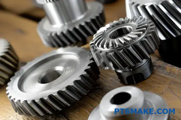
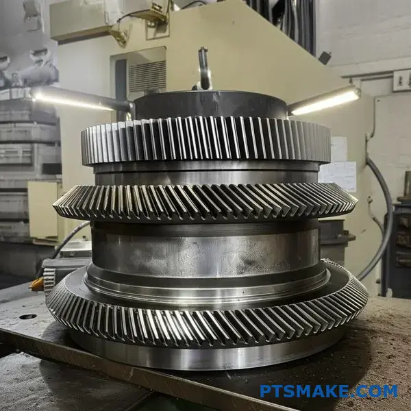
What are the main categories of driven gears by axis orientation?
The first step in gear selection is simple. How are the shafts oriented? This question is the starting point for any mechanical design involving gears.
Your answer will place the required driven gear into one of three fundamental categories. This initial classification dictates the entire design path forward.
Parallel Shafts
When shafts run parallel, spur or helical gears are used. They are the most common arrangement for transmitting power and changing speed or torque.
Intersecting & Non-Intersecting Shafts
For shafts that cross paths, the choice is different. This setup is crucial for changing the direction of power flow.
A simple table can clarify this:
| Shaft Orientation | Common Gear Types | Primary Application |
|---|---|---|
| Parallel | Spur, Helical | Speed and torque modification |
| Intersecting | Bevel | Changing power direction |
| Non-Parallel, Non-Intersecting | Worm, Hypoid | High reduction ratios, offset axes |
This framework is the first filter in the gear selection process.
At PTSMAKE, we always begin client discussions with this fundamental question. Getting the axis orientation right from the start prevents significant redesigns and costly errors later. It’s a non-negotiable first step.
Parallel Axis Gears In-Depth
For parallel shafts, the choice between spur and helical gears comes down to application specifics. Spur gears are simpler and cost-effective for moderate speeds.
Helical gears, with their angled teeth, provide smoother and quieter operation. This makes them ideal for high-speed or noise-sensitive applications, like in automotive transmissions.
Intersecting Axis Gears Explained
Bevel gears are the go-to solution when shaft axes intersect, typically at a 90-degree angle. Their conical shape is specifically designed to transfer power between perpendicular shafts.
The precision of these gears is critical. In our past projects, we’ve seen that even minor inaccuracies in the cone angle can lead to premature wear and system failure.
Non-Parallel, Non-Intersecting Shafts
This category is for more complex geometries. Worm and hypoid gears solve the challenge of transmitting power between shafts that are offset and do not cross.
These gears allow for high gear reduction ratios in a compact space. The sliding contact between the teeth requires careful material selection and lubrication. The theoretical pitch surface9 of these gears is what allows for motion transfer across non-intersecting axes, a truly unique geometric solution.
Understanding your shaft orientation is the most critical first step. This single decision about parallel, intersecting, or non-parallel axes dictates which driven gear family is suitable. It directly impacts system layout, performance, efficiency, and cost, forming the foundation of your design.
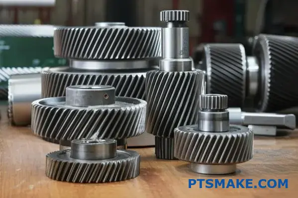
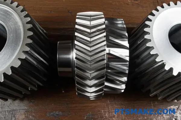
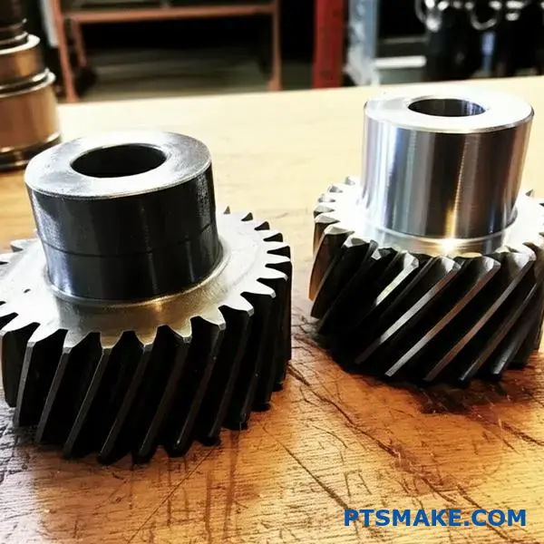
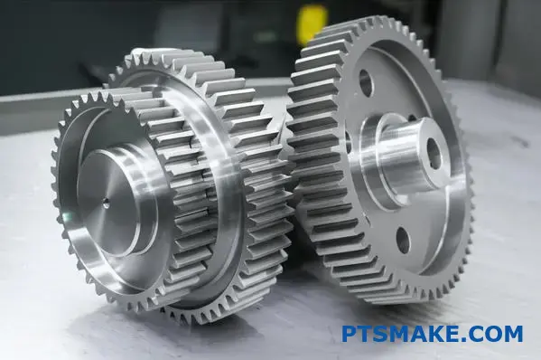
How do spur, helical, and double helical gears compare practically?
Choosing the right gear comes down to balancing performance, cost, and complexity. Each type has a distinct practical application.
Spur gears are the simplest and most cost-effective. Helical gears offer smoother, quieter operation. Double helical gears provide the benefits of helical gears without the drawbacks.
Here is a quick comparison:
| Gear Type | Key Practical Feature | Common Trade-Off |
|---|---|---|
| Spur | Simple, Low Cost | Noisy, Lower Load |
| Helical | Quiet, High Load | Creates Axial Thrust |
| Double Helical | Quiet, No Thrust | Complex, Expensive |
This choice directly impacts your machine’s performance and budget.
Let’s break down the practical trade-offs further. Spur gears are straightforward to manufacture. This makes them a great choice for applications where noise isn’t a major concern and cost is a key driver.
Helical gears, with their angled teeth, engage more gradually. This leads to less vibration and quieter performance. However, this angled design creates axial thrust10. This side force must be managed with appropriate bearings, which adds complexity and cost to your assembly.
Double helical, or herringbone, gears are the premium solution. They use two sets of opposing helical teeth. This clever design cancels out the axial thrust internally. You get the smooth, high-load benefits of helical gears without the external force management.
In past projects at PTSMAKE, we have seen the manufacturing cost for double helical gears be significantly higher than for spur gears.
This is due to the complex geometry. The decision often depends on the specific demands of the driven gear system.
| Criteria | Spur Gear | Helical Gear | Double Helical Gear |
|---|---|---|---|
| Noise Level | High | Low | Very Low |
| Load Capacity | Good | Better | Best |
| Manufacturing Cost | Low | Medium | High |
| Axial Thrust | None | Yes | None |
| Typical Use Case | Simple Conveyors | Automotive Transmissions | Heavy Machinery |
Ultimately, the best choice is the one that meets your performance needs without over-engineering the solution.
Your gear choice is a critical design decision. Spur gears offer simplicity and low cost. Helical gears provide quiet, high-load performance but create axial thrust. Double helical gears eliminate thrust but are the most expensive to produce.
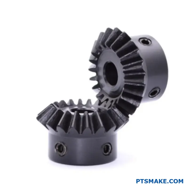
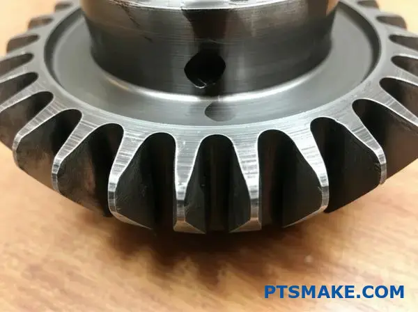
When should a bevel or miter gear be the chosen solution?
The primary reason to choose a bevel or miter gear is simple. You need to change the direction of power transmission. Most often, this means making a 90-degree turn.
While other gear types handle parallel shafts, bevel gears are specialists for intersecting shafts. They are the go-to solution for right-angle applications. Miter gears are just a specific type of bevel gear.
The key difference lies in their gear ratio.
| Gear Type | Gear Ratio | Primary Use |
|---|---|---|
| Miter Gear | 1:1 | Direction change only |
| Bevel Gear | Any | Direction, speed, & torque change |
This distinction is crucial for selecting the right component for your design.
Miter vs. Bevel: Ratio is Everything
Let’s break this down further. The choice impacts your machine’s speed and torque output directly. It’s a detail we always confirm with clients at PTSMAKE before starting production.
Miter Gears for Simple Directional Change
Miter gears are a matched pair. They both have the same number of teeth and their shaft axes are 90 degrees apart. Because the ratio is exactly 1:1, the speed and torque of the driven gear are identical to the driving gear.
Think of a simple conveyor system. A miter gear can transfer power from a horizontal driveshaft to a vertical one to run rollers, without altering the conveyor’s speed.
Bevel Gears for More Complex Tasks
Other bevel gears offer more flexibility. By changing the number of teeth on the drive and driven gear, you can change the ratio. This allows you to alter speed and torque while turning the corner. The geometry of the pitch cone11 determines this relationship.
The best example is an automotive differential. It uses bevel gears to transmit power to the wheels at a 90-degree angle. More importantly, it allows the outer wheel to spin faster than the inner one during a turn.
| Application Example | Required Ratio | Suitable Gear |
|---|---|---|
| Hand Drill Mechanism | 1:1 | Miter Gear |
| Automotive Differential | Variable | Bevel Gear |
| Industrial Right-Angle Drive | >1:1 or <1:1 | Bevel Gear |
In short, miter gears are perfect for 1:1 ratio, 90-degree directional changes. For applications requiring a change in speed or torque alongside the directional shift, other bevel gears are the necessary choice. Your specific mechanical requirements will dictate the solution.
What specific applications demand worm and wheel gear sets?
Two key traits make worm gears essential for certain jobs. First, they offer huge transmission ratios in one step. Think 100:1, which is hard to get otherwise.
Second, they are self-locking. This means the output gear cannot drive the input worm. This is a critical safety feature.
Core Characteristics
These features drive their selection in demanding applications. They provide both massive speed reduction and inherent braking.
| Feature | Description |
|---|---|
| High Ratio | Achieves significant speed reduction and torque multiplication in a compact space. |
| Self-Locking | Prevents the load from back-driving the motor, enhancing safety and control. |
This combination is unique in the world of gearing.
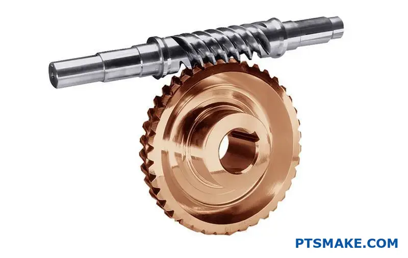
Worm and wheel sets are not just a theoretical concept. We see them solve real-world problems. Their unique mechanics are perfect for specific industries where precision and safety are non-negotiable. The high friction between the worm and the driven gear creates these valuable properties.
Applications in Action
In past projects, we’ve seen these gears used where other systems would fail. Their simplicity and effectiveness are hard to match for certain tasks.
Conveyor Systems
Conveyor belts often need a large speed reduction. A high-speed motor must be slowed down to move the belt at a usable pace. A worm gear set does this easily in a single stage. The self-locking feature also holds the belt steady when the motor stops.
Lifting Mechanisms
Think about elevators or material lifts. Safety is the top priority. If power fails, the self-locking nature of the worm gear prevents the cabin from falling. The high sliding friction12 between the components creates this braking effect. It’s a built-in safety measure.
| Application | Primary Characteristic Used | Key Benefit |
|---|---|---|
| Elevators | Self-Locking | Safety (prevents free-fall) |
| Conveyor Belts | High Transmission Ratio | Speed Control & Torque Increase |
| Tuning Heads | Self-Locking | Holds Position (stays in tune) |
Worm gear sets are chosen for their unique combination of high-ratio speed reduction and self-locking capability. These two features make them indispensable for applications requiring precise control, compact design, and inherent safety, from industrial conveyors to elevators.
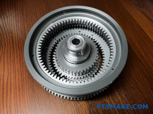
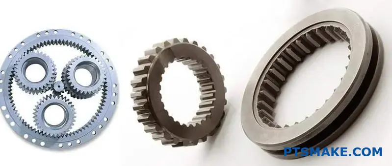
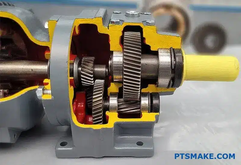
How do planetary gear systems structure power flow uniquely?
Planetary gear systems are engineering marvels. Their power flow is unlike any other gear train. It all comes from three core components.
The Key Players
The sun gear is at the center. Planet gears orbit the sun gear. The ring gear encloses the entire assembly.
By choosing which part to hold still, which to power, and which to take power from, you completely change the output. This versatility is their unique strength.
| Component | Role in the System |
|---|---|
| Sun Gear | The central driving or stationary gear |
| Planet Gears | Orbit the sun gear, meshing with sun and ring |
| Ring Gear | The outer gear with internal teeth |
This setup allows for multiple gear ratios from a single, compact unit.
Unlocking Versatility and Power
The true genius of a planetary system is its adaptability. It isn’t just one gear set. It’s a configurable platform for managing torque and speed. The relationship between the input, output, and a fixed component defines its function.
At PTSMAKE, we often leverage this for custom applications. It allows us to achieve complex motion requirements within very tight spaces.
Modes of Operation
How you use the components determines the result. For instance, fixing the ring gear and driving the sun gear creates a specific reduction. The planet gears transmit torque as the coaxial13 output. The planet carrier acts as the final driven gear component.
| Fixed Component | Input Component | Output Component | Result |
|---|---|---|---|
| Ring Gear | Sun Gear | Planet Carrier | Speed Reduction |
| Sun Gear | Ring Gear | Planet Carrier | Speed Reduction |
| Planet Carrier | Sun Gear | Ring Gear | Reverse & Reduction |
The Coaxial Advantage
This system also offers incredible power density. Multiple planet gears share the load. This means a small package can handle immense torque.
Furthermore, the input and output shafts are coaxial. They share the same centerline. This simplifies the design of transmissions and other complex machinery significantly.
Planetary gear systems structure power flow through the interaction of a sun, planets, and ring gear. Their unique ability to be configured for different outputs, combined with high power density and a coaxial design, makes them exceptionally versatile for complex machinery.
What distinguishes an internal from an external driven gear?
When designing a system, the choice between gear types is crucial. It’s a practical decision that impacts everything. Your product’s final size, cost, and performance are on the line.
External gears are the familiar standard. Internal gears offer unique benefits but come with challenges. Understanding these trade-offs is key.
Key Design Differences
Let’s break down the core distinctions from a design perspective. This helps clarify which might fit your project.
| Feature | Internal Gear | External Gear |
|---|---|---|
| Size | More compact footprint | Requires more space |
| Manufacturing | Complex, specialized | Simpler, widely available |
| Performance | Higher contact ratio | Standard performance |
| Cost | Generally higher | More cost-effective |
This table shows the fundamental trade-off. You often balance compactness against manufacturing simplicity.
Practical Application and Manufacturing
From a practical standpoint, external gears are the go-to for many projects. Their manufacturing process is straightforward. This simplicity often leads to lower costs and shorter lead times, a critical factor for many clients we work with at PTSMAKE. They are easy to produce and mount, making them reliable workhorses.
Internal gears solve a different set of problems. Their main advantage is creating a very compact gear drive. This is because the driven gear meshes internally, saving significant space. They also provide a higher contact ratio14, which means more teeth are engaged at once. This can lead to smoother operation and a higher load capacity.
Choosing the Right Gear
The difficulty in manufacturing internal gears is a major consideration. Cutting teeth on an inside surface requires specialized tooling and expertise. This complexity directly impacts the final part cost. In past projects at PTSMAKE, we weigh these factors carefully with our clients. The application always dictates the best choice.
Here are some common examples:
| Gear Type | Application Examples |
|---|---|
| Internal Gear | Planetary gear systems in robotics, automatic transmissions, bicycle hub gears. |
| External Gear | Simple industrial machinery, conveyor belt systems, traditional clock mechanisms. |
For a high-torque robotic arm where space is minimal, an internal gear is often the only viable option. For a straightforward power transmission system, an external gear is usually the most practical and economical solution.
In summary, your choice depends on project priorities. External gears offer standard, cost-effective solutions. Internal gears provide compact, high-performance designs for more specialized applications where space and load capacity are critical design drivers.
What are the common failure modes for different gear types?
Understanding gear failures is crucial. It’s not just about a broken part. It’s about finding the root cause. Failures can be sorted into clear groups. This helps diagnose issues faster.
At PTSMAKE, we categorize failures to improve our designs. The main groups are wear, fatigue, breakage, and plastic flow. A well-made driven gear resists these better.
| Failure Category | Description |
|---|---|
| Tooth Wear | Gradual material loss |
| Surface Fatigue | Cracking from repeated stress |
| Tooth Breakage | Sudden, catastrophic fracture |
| Plastic Flow | Surface material deformation |
To prevent failures, we must first understand them. Let’s break down the common categories we see in gear systems. Each has distinct causes and signs.
Tooth Wear
This is the slow removal of material from gear teeth. It often happens over time.
Abrasive Wear
Abrasive wear occurs when hard particles contaminate the lubricant. These particles act like sandpaper, scratching the gear surfaces. Proper filtration is key to prevention.
Adhesive Wear
Adhesive wear happens when gear teeth surfaces weld together and then tear apart. This is often caused by high loads and poor lubrication. It creates a rough surface.
Surface Fatigue
This results from repeated stress cycles on the tooth surface. It starts with tiny cracks that grow over time.
Pitting and Spalling
Pitting creates small cavities on the tooth surface. As these pits grow and join, they can lead to spalling15, where larger chunks of material break away. This is a common failure mode.
Tooth Breakage
This is a more severe and sudden failure.
Bending Fatigue
Repeated bending stress at the tooth root can cause a crack to form. The crack grows with each cycle until the tooth breaks off completely.
Overload Breakage
This happens when the load on the gear exceeds its strength. It results in a sudden, brittle fracture of the tooth.
| Failure Mode | Common Cause | Prevention Strategy |
|---|---|---|
| Abrasive Wear | Contaminated lubricant | Better filtration, sealed housing |
| Adhesive Wear | Poor lubrication, high load | Use proper lubricant, reduce load |
| Pitting | High contact stress | Improve gear geometry, better material |
| Overload Breakage | Shock loads, sudden jam | Overload protection, stronger materials |
Categorizing gear failures into wear, fatigue, breakage, and plastic flow allows for accurate diagnosis. Understanding that causes like misalignment or poor lubrication lead to specific failures is the first step toward building more reliable systems and preventing downtime.
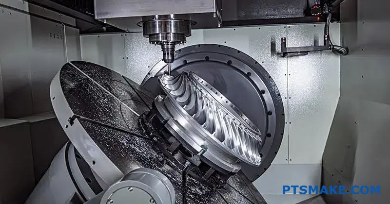
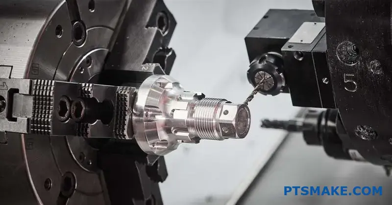
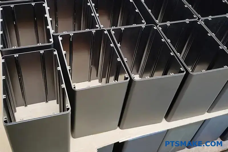
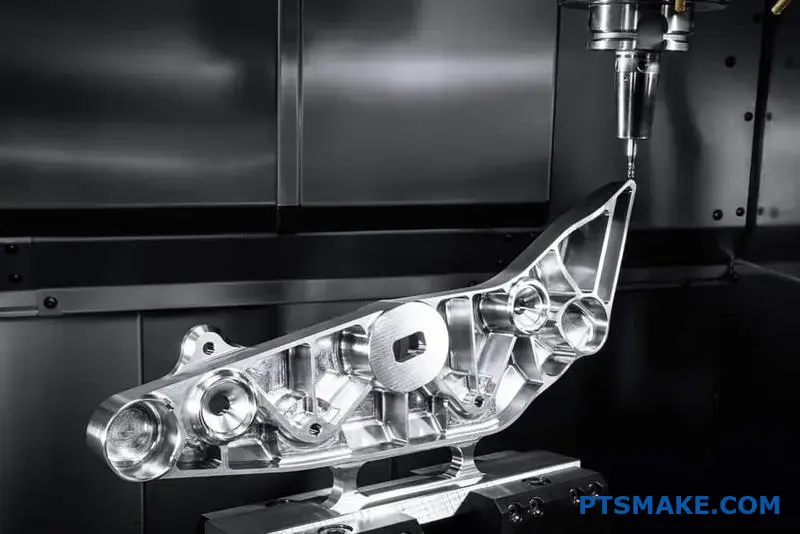
How are gear manufacturing processes classified for practical selection?
Choosing the right gear manufacturing process can feel complex. A practical way to simplify this is by grouping methods by their outcome and cost. This helps you match the process to your specific application’s needs.
We can classify them into three main categories.
Forming for Blanks
These methods, like casting or forging, are for creating the initial gear shape. They are cost-effective for high volumes but offer lower precision.
Machining for General Use
Processes like hobbing and shaping cut teeth into the blank. They provide good accuracy for most industrial needs.
Finishing for High Precision
Grinding and lapping refine the gear teeth. These steps are expensive but necessary for applications demanding high precision and low noise, such as a critical driven gear.
The Precision-Cost Trade-Off
At PTSMAKE, we guide clients through the crucial balance between gear precision and manufacturing cost. It’s not always about choosing the highest precision; it’s about selecting the right precision for the job. This decision directly impacts your budget and project timeline.
Forming Processes: The Foundation
Forming methods like forging create strong gear blanks. The precision is low, typically around AGMA Q5-Q7. However, they are ideal for producing large quantities of blanks that will be machined later. This two-step approach is often very cost-effective.
Machining Processes: The Workhorse
Machining, including hobbing and shaping, is the most common method. It delivers reliable precision for a wide range of applications, usually in the AGMA Q8-Q11 range. This is the sweet spot for general industrial machinery where performance and cost are balanced.
Finishing Processes: The Final Touch
For applications in aerospace or medical devices, finishing is essential. Processes like grinding and lapping achieve extremely high precision (AGMA Q12+). This level of kinematic accuracy16 ensures quiet, smooth operation but comes at a significantly higher cost.
The table below summarizes this trade-off.
| Process Group | Typical Precision (AGMA) | Relative Cost | Best For… |
|---|---|---|---|
| Forming | Q5 – Q7 | Low | High-volume blanks, non-critical parts |
| Machining | Q8 – Q11 | Medium | General industrial applications |
| Finishing | Q12 – Q15 | High | Aerospace, low-noise systems |
In essence, classifying manufacturing processes by outcome and cost simplifies selection. Forming is for low-cost blanks, machining for general-purpose gears, and finishing for high-precision applications. Your final choice always involves a trade-off between performance requirements and budget.
What heat treatment structures are applied to driven gears?
Choosing the right heat treatment is crucial. It defines a driven gear’s service life. The goal is a perfect balance. We need hardness for wear resistance. We also need toughness to prevent fractures.
This isn’t a one-size-fits-all solution. The choice depends entirely on the gear’s specific job. At PTSMAKE, we match the treatment to the application’s demands.
Here’s a quick overview of the two main approaches:
| Treatment Type | Primary Goal | Core Property |
|---|---|---|
| Case Hardening | Hard, wear-resistant surface | Tough and ductile |
| Through Hardening | Uniform hardness and strength | Uniform properties |
This ensures the driven gear performs reliably under its intended load.
Let’s explore these methods from a practical standpoint. The decision impacts not just performance but also manufacturing complexity and cost. It’s a key discussion we have with clients early in the design phase.
Case Hardening Techniques
Case hardening creates a dual-structure component. You get a hard exterior for wear and a tough, shock-absorbing interior. This is ideal for high-stress applications where impact and surface wear are major concerns.
Carburizing
This process involves adding carbon to the surface of low-carbon steel. The part is heated in a carbon-rich atmosphere. The result is an extremely hard outer case, perfect for handling heavy contact loads without wearing down quickly.
Nitriding
Nitriding uses nitrogen to harden the surface. It’s a lower-temperature process, which means less risk of distortion. This makes it an excellent choice for a precision driven gear where tight tolerances are critical after treatment. The martensitic transformation17 is less of a concern here regarding distortion.
Through Hardening
Through hardening, as the name implies, hardens the entire gear uniformly. The gear is heated and then quenched. This method is simpler and often more cost-effective. It’s best for applications with lower contact stress where overall strength and fatigue resistance are more important than extreme surface durability.
| Feature | Carburizing | Nitriding | Through Hardening |
|---|---|---|---|
| Surface Hardness | Very High | High | Moderate |
| Core Toughness | High | High | Moderate |
| Distortion Risk | High | Low | Medium |
| Best For | Heavy loads | Precision parts | Uniform stress |
The choice between case hardening and through hardening for a driven gear depends on its specific operational stresses. Case hardening excels in high-wear scenarios, while through hardening provides consistent strength for lower-load applications, ensuring optimal performance and longevity.
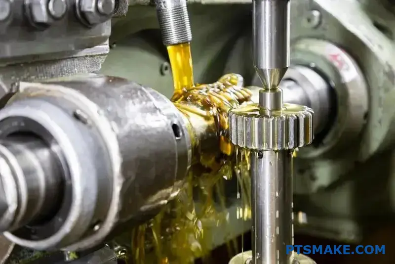
How do lubrication systems vary for different gear applications?
Choosing the right lubrication is not a one-size-fits-all task. The method must match the application’s demands. Speed and load are the two most critical factors.
They determine whether a simple grease application is enough. Or if a more complex system is needed. This choice directly impacts gear life and performance. Let’s explore the common types.
Grease Lubrication
Grease is ideal for low-speed and low-load situations. It’s often used in sealed units that are "lubricated for life." Think of small appliance gearboxes. Maintenance is minimal, which is a big advantage.
Splash Lubrication
For moderate speeds and loads, splash lubrication is common. This system is used in many enclosed industrial gearboxes. A gear, or a slinger attached to it, dips into an oil bath. It splashes lubricant onto other components.
Forced (Pressure) Lubrication
High-speed, high-load systems require a more robust solution. Forced lubrication actively pumps oil to critical contact points. This includes bearings and gear meshes. This method ensures consistent lubrication for every component. It also provides essential cooling and filtration.
Forced lubrication systems are where precision matters most. In these high-stress environments, every component must perform flawlessly. This includes the oil jets, pumps, and filters.
At PTSMAKE, we machine components for these complex systems. The tolerances are incredibly tight. Any failure can lead to catastrophic damage.
A major benefit is heat dissipation. The circulating oil carries away heat generated by friction. This is vital in high-performance applications. Without it, gears would quickly overheat and fail.
The system also filters the lubricant. It removes metal particles and contaminants. This keeps the oil clean and extends the life of the gears. The proper function of the driving and driven gear pair depends on this clean oil. This is a core concept in Tribology18.
We can compare these methods directly.
| Lubrication Method | Typical Speed | Typical Load | Complexity & Cost | Typical Application |
|---|---|---|---|---|
| Grease | Low (<2 m/s) | Low to Moderate | Low | Sealed gear units, intermittent use |
| Splash | Moderate (2-12 m/s) | Moderate | Medium | Enclosed industrial gearboxes |
| Forced (Pressure) | High (>12 m/s) | High | High | Automotive transmissions, turbines |
This table helps our clients understand the trade-offs. Matching the system to the application is key for reliability and cost-effectiveness.
Selecting the right lubrication depends heavily on the gear’s speed and load. Simple grease works for slow applications, while high-performance systems demand complex forced lubrication for cooling and filtration, ensuring longevity and reliability for every gear, including the driven gear.
How do you calculate the gear ratio for a simple train?
Calculating the gear ratio for a simple gear train is straightforward. It is a fundamental concept in mechanical engineering. This calculation helps you understand the output.
The entire process relies on one simple formula. You just need to count the teeth on two gears.
The Core Formula
The ratio is found by dividing the number of teeth on the driven gear by the number of teeth on the driving gear. The driven gear is the one that receives the force.
A Simple Guide
- Identify the driving gear (input).
- Identify the driven gear (output).
- Count the teeth on both.
- Apply the formula.
Here’s a quick reference:
| Gear Type | Description |
|---|---|
| Driving Gear | The gear that is powered and initiates motion. |
| Driven Gear | The gear that is turned by the driving gear. |
The result gives you the gear ratio.
Understanding the formula is just the beginning. The real value comes from knowing what this ratio means for your machine’s performance. It directly controls the trade-off between speed and torque.
Impact on Output Speed
The gear ratio determines the output speed. A higher ratio means a lower output speed. The formula is:
Output Speed = Input Speed / Gear Ratio
For example, a 2:1 ratio halves the speed. The driven gear rotates once for every two rotations of the driving gear. This is crucial for precision control. In past projects at PTSMAKE, we’ve used this to achieve exact movement speeds.
Understanding Torque Multiplication
Torque is the rotational force. The gear ratio also multiplies torque. Ignoring efficiency losses, the formula is:
*Output Torque = Input Torque Gear Ratio**
This principle is the foundation of mechanical advantage19. It allows a small motor to move a heavy load. A larger driven gear provides more torque but at a slower speed.
The relationship is inverse, as shown below:
| Gear Ratio | Effect on Speed | Effect on Torque |
|---|---|---|
| > 1:1 | Decreases | Increases |
| < 1:1 | Increases | Decreases |
| 1:1 | No Change | No Change |
This balance is a key consideration in any gear design project.
Calculating the gear ratio involves dividing the driven gear’s teeth by the driving gear’s teeth. This simple number dictates the final output speed and torque, allowing you to manipulate force and velocity to meet your application’s specific needs.
How would you redesign a gear drive for higher efficiency?
Reducing energy loss is key to a more efficient gear drive. Small changes can lead to significant gains. It’s not just about one fix; it’s a series of targeted improvements.
From Spur to Helical Gears
Switching gear types offers a major advantage. Helical gears provide smoother, quieter operation and better contact.
The Role of Surface Finish
A smoother surface means less friction. Grinding and polishing gear teeth can drastically reduce energy waste.
| Strategy | Primary Benefit |
|---|---|
| Helical Gears | Smoother power transmission |
| Grinding | Lower friction |
| Lubrication | Reduced wear and heat |
| Bearings | Minimized rotational resistance |
A Deeper Look at Loss Reduction
Achieving higher efficiency requires a multi-faceted approach. Each component plays a critical role in minimizing friction and wasted energy. It’s a system where every detail matters.
Optimizing Gear Contact
We often recommend helical gears over spur gears. Their angled teeth engage more gradually. This spreads the load over a larger surface area, reducing stress and frictional losses. In past projects at PTSMAKE, this simple change has improved efficiency.
The Importance of Lubrication
Proper lubrication is crucial. It’s about more than just applying oil. The science of Tribology20 shows that viscosity and quantity are critical. Too much lubricant can cause drag, while the wrong viscosity fails to create a protective film. This is especially true for the driven gear, which handles the output load.
Bearings and Surface Quality
High-quality bearings are a must. They minimize rotational friction, a direct source of energy loss. We also focus on surface finish. Through advanced grinding techniques, we create ultra-smooth gear tooth surfaces that slide past each other with minimal resistance.
| Component | Key Optimization | Impact on Efficiency |
|---|---|---|
| Gears | Switch to Helical | Reduces impact and friction |
| Lubricant | Correct Viscosity | Creates stable film, avoids drag |
| Bearings | High-Quality Roller/Ball | Lowers rotational friction |
| Surface | Precision Grinding | Minimizes microscopic friction |
Achieving higher efficiency is a systematic process. It involves upgrading to better gear geometry, optimizing lubrication, improving surface finish, and using high-quality bearings. Each step contributes to reducing friction and overall energy loss in the system.
How do you mitigate gear noise and vibration in a system?
Tackling gear noise requires a system-level view. It’s not just about the gear itself. You must consider the entire assembly.
This approach looks at everything from gear design to the housing. Factors like gear precision and alignment play a huge role. A well-designed system minimizes noise from the start. Both the driving and driven gear need careful consideration.
A System-Wide Strategy
Thinking beyond a single component is key. Effective noise reduction comes from a holistic strategy.
| Approach | Focus | Outcome |
|---|---|---|
| Component-Level | A single gear | Limited noise reduction |
| System-Level | Entire assembly | Optimal performance |
This ensures a quieter, more reliable final product.
To truly reduce noise and vibration, we must analyze the entire power transmission system. It’s an issue I’ve helped many clients at PTSMAKE solve by looking at the bigger picture.
Advanced Mitigation Techniques
Gear Design and Quality
The gear’s design is your first line of defense. Using helical gears instead of spur gears can significantly increase the Contact Ratio21. This allows for a smoother, quieter transfer of power.
Improving gear quality is also critical. We often specify a higher AGMA class for precision. A higher class means tighter tolerances and a better surface finish, which reduces noise. Modifying the tooth profile, such as adding tip or root relief, also prevents interference and lowers vibration.
Alignment and Housing
Perfect alignment is non-negotiable. Misaligned gears, shafts, or bearings are a primary source of noise. This includes the positioning of the driven gear relative to the driver. Proper assembly is just as important as manufacturing precision.
The housing’s role is often underestimated. A rigid housing with good damping characteristics can absorb vibrations before they become audible noise.
| Mitigation Technique | Primary Goal | System Component |
|---|---|---|
| Helical Gears | Increase contact ratio | Gear |
| Higher AGMA Class | Improve precision | Gear |
| Tooth Profile Modification | Reduce interference | Gear |
| Proper Alignment | Ensure correct meshing | Assembly |
| Damping Housing | Absorb vibrations | Housing |
Effective noise control combines these strategies for the best result.
Effective gear noise mitigation is a system-level challenge. Success depends on integrating smart design choices, high-precision manufacturing, and careful assembly. It’s about how all the parts work together, not just one component in isolation.
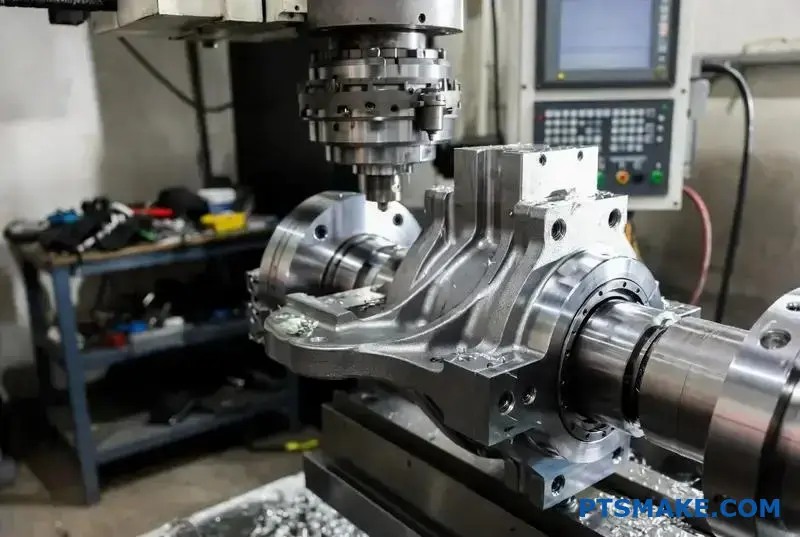
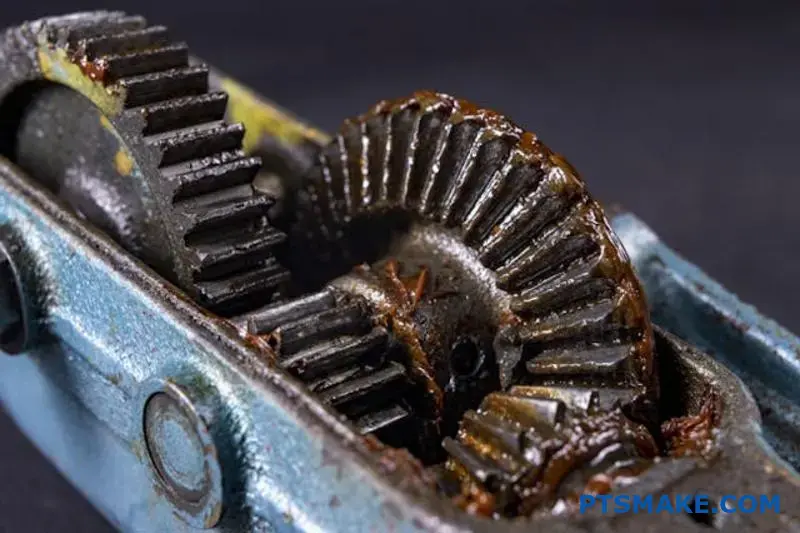
Analyze a case study of a premature driven gear failure.
Let’s examine a wind turbine gearbox failure. This is a critical application where a premature breakdown is costly. The main driven gear failed after just five years. The expected lifespan was twenty years.
Initial Observations
We start by gathering the basic facts. The failure was not sudden. Performance degraded over several months before a complete stop. This suggests a progressive failure mechanism.
Key Data Points
| Parameter | Observation |
|---|---|
| Operating Hours | ~44,000 hours |
| Expected Lifespan | ~175,000 hours |
| Failure Mode | Excessive vibration, then seizure |
| Maintenance Log | Regular, on schedule |
This initial data helps us frame the problem. The gear did not meet its design life despite proper maintenance.
Applying the Failure Analysis Procedure
In projects at PTSMAKE, we follow a strict procedure. This ensures we don’t jump to conclusions. We apply this same logic here to find the true root cause. A systematic approach is crucial.
Step 1: Visual and Microscopic Examination
First, we looked at the failed driven gear. The gear teeth showed significant surface distress. There was clear evidence of widespread micropitting22 across the tooth flanks. This wasn’t a simple overload fracture. The damage was consistent with long-term fatigue. It indicated a problem with the lubrication film.
Step 2: Lubricant and Debris Analysis
Next, we analyzed the gear oil. Our lab tests found a high concentration of metallic particles. This confirmed excessive wear was happening. The oil’s viscosity was also lower than specified. This was a major red flag. A lower viscosity reduces the lubricant film’s strength.
Step 3: Identifying the Root Cause
We compiled the evidence. The premature failure was not due to a material defect or a shock load. The root cause was lubrication starvation. The incorrect lubricant grade was used during a previous service. This led to inadequate film thickness, increased friction, and ultimately, catastrophic surface fatigue.
| Potential Cause | Evidence | Conclusion |
|---|---|---|
| Material Defect | Material analysis showed correct composition. | Ruled Out |
| Shock Loading | No evidence of sudden fracture. | Ruled Out |
| Lubrication Starvation | Widespread micropitting, low oil viscosity. | Most Likely Cause |
Proposed Corrective Actions
The solution involves more than just replacing the gear. We must update maintenance protocols. This includes stricter lubricant verification. Training staff on the importance of using the correct oil grade is essential for preventing a recurrence.
This case study shows how a systematic analysis identified lubrication failure as the root cause, not a material flaw. Correctly diagnosing the problem is key to implementing effective and lasting corrective actions for any driven gear system.
How does thermal expansion affect gear performance in high-temp applications?
In high-temperature environments, gears face a silent threat: thermal expansion. As metal heats up, it grows. This simple fact has huge consequences for gear systems.
The most immediate problem is reduced backlash. Backlash is the small gap between mating gear teeth. It’s essential for lubrication and preventing jams.
When gears expand, this gap shrinks. If it disappears completely, the gears can bind, leading to catastrophic failure. Understanding this is key to reliable design.
The Consequences of Vanishing Backlash
When backlash is eliminated by heat, gears start to interfere. This increases friction, generates more heat, and accelerates wear on every part, including the driven gear.
| Backlash State | Consequence | Risk Level |
|---|---|---|
| Sufficient | Smooth operation, proper lubrication | Low |
| Reduced | Increased noise, friction, and heat | Medium |
| Zero/Negative | Binding, tooth failure, system seizure | High |
This cycle can quickly lead to a complete system breakdown.
Managing Thermal Expansion in Gear Design
At PTSMAKE, we manage these effects through careful engineering. It’s not about fighting physics, but designing with it in mind. Three key strategies are essential for success.
Specify Larger Cold Backlash
The most direct solution is to design a larger initial backlash at ambient temperature (cold backlash).
This extra space acts as a buffer. It ensures that even after the gears expand to their operating temperature, a sufficient gap remains for lubrication and smooth meshing. Calculating this requires precise knowledge of the materials and temperatures involved.
Material Selection is Crucial
Choosing the right materials is another critical step. Ideally, the gear and its housing should expand at similar rates.
Each material has a unique Coefficient of Thermal Expansion23, which dictates how much it grows when heated. We focus on selecting materials with compatible coefficients to maintain clearances across the operating temperature range.
This applies to both the drive and the driven gear, ensuring they expand compatibly with each other and the housing.
| Material | Typical Application Benefit | Thermal Stability |
|---|---|---|
| Steel Alloys | High strength and durability | Good |
| Bronze Alloys | Good lubricity, lower friction | Moderate |
| PEEK/Plastics | Lightweight, corrosion resistant | Varies |
Use High-Temperature Lubrication
Finally, lubrication is non-negotiable. Standard lubricants can break down or burn off at high temperatures, leaving the gears unprotected.
We always specify lubricants engineered for high-heat environments. These fluids maintain their viscosity and protective film, reducing friction and helping to dissipate heat, even when clearances are tight.
Reduced backlash from heat is a serious risk. It can cause binding and failure. Smart design with larger cold backlash, compatible materials, and proper high-temperature lubrication effectively manages this threat, ensuring reliable gear performance.
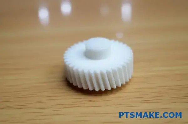
When is a plastic driven gear a superior choice over metal?
Choosing between plastic and metal isn’t about which is "better." It’s about which is right for your specific application. A plastic driven gear can be a game-changer in the right context.
Think about the quiet hum of an office printer. That’s plastic at work.
Key Advantages in Action
Quiet Operation
Plastic gears naturally dampen vibration and noise. This makes them ideal for consumer electronics and office equipment where silence is a feature.
Self-Lubrication
Many engineering plastics have low coefficients of friction. They can run smoothly without external lubrication, reducing maintenance and contamination risks.
| Feature | Plastic Driven Gear | Metal Driven Gear |
|---|---|---|
| Noise Level | Very Low | Higher |
| Lubrication | Often Self-Lubricating | Requires External Lubricant |
| Corrosion | Excellent Resistance | Prone to Rust/Corrosion |
| Weight/Inertia | Very Low | High |
This low inertia also means they can start and stop quickly with less energy.
However, plastic is not a universal solution. Understanding its limitations is crucial for successful product design. At PTSMAKE, we guide clients through these trade-offs daily to avoid costly errors.
Understanding the Trade-Offs
Load Capacity and Temperature
The primary limitation of a plastic driven gear is its lower strength. For high-torque or high-load applications, metal remains the default choice. Plastics also have a narrower operating temperature range and can soften or become brittle at extremes.
Dimensional Stability
Plastics can be sensitive to their environment. For instance, Hygroscopic expansion24 from moisture absorption can alter a gear’s dimensions, affecting its precision. This is a critical factor in applications requiring tight tolerances.
Where Plastic Gears Shine
They are perfect for applications where their benefits outweigh their limitations.
| Factor | Best for Plastic Gears | Best for Metal Gears |
|---|---|---|
| Load | Low to Medium | High to Very High |
| Environment | Clean, Controlled | Harsh, Abrasive |
| Noise | Quiet Operation | Noise is Tolerable |
| Cost | Lower (Mass Production) | Higher |
Consider automotive interiors. The motors for your power windows or seats don’t handle massive loads. Here, the low weight, quiet operation, and corrosion resistance of plastic are far more valuable than the raw strength of metal.
Plastic gears offer significant advantages in noise reduction, self-lubrication, and corrosion resistance. However, their lower load capacity and temperature sensitivity make metal the superior choice for high-stress applications. The final decision always hinges on the specific operational demands of the product.
How do you balance gear life, cost, and performance in design?
This is the core trade-off in gear design. Think of it as a triangle with three corners: Life, Cost, and Performance.
You can’t have the best of all three. Improving one corner almost always compromises another.
For example, a high-performance driven gear often means higher costs. The goal is finding the right balance for your specific application. It’s about being "good enough" without wasteful over-engineering.
This balance is key to a successful product.
| Focus Point | Primary Impact | Secondary Impact |
|---|---|---|
| Performance | Higher Material/Machining Costs | Can Affect Size/Weight |
| Life | Increased Cost (Finishing, Size) | May Reduce Max Performance |
| Cost | Lower Performance Specs | Reduced Operational Lifespan |
The Engineering Triangle in Practice
Critically, the ideal gear is not the one with the highest performance. It’s the one that meets all requirements reliably for the lowest possible cost. This is a constant balancing act we manage at PTSMAKE.
Defining Performance
Performance can mean many things. It might be higher precision (tighter tolerances), better materials for strength, or a design that handles higher speeds and loads. Each improvement adds manufacturing complexity and, therefore, cost.
Understanding Gear Life
Gear life is influenced by factors like material hardness, surface finishing, and size. A larger gear or one with special heat treatment will last longer. But it will also be more expensive to produce and might not fit in a compact design. Calculating the Hertzian contact stress25 is crucial here.
The ‘Good Enough’ Point
Over-engineering is a common pitfall. A gear designed to last 30 years in a product with a 5-year life cycle is a waste of money. The goal is to find that sweet spot where the gear performs its function reliably for its intended lifespan, and no more.
| Design Goal | Material Example | Process Example | Typical Outcome |
|---|---|---|---|
| Low Cost | Standard plastic | Injection Molding | Fast production, for light-duty uses. |
| Balanced | Alloy Steel | CNC Machining | Good life and performance for most uses. |
| High Life | Hardened Steel | Grinding & Polishing | Very long life, highest cost. |
This balance is the essence of effective engineering. The goal is not perfection in one area but optimization across all three constraints—life, cost, and performance. This ensures the final product is both reliable and commercially viable, avoiding unnecessary expense from over-engineering.
Unlock Superior Driven Gear Solutions with PTSMAKE Expertise!
Ready to elevate your next driven gear project? Partner with PTSMAKE for precision engineering, reliable lead times, and top-tier quality from prototype to production. Send us your RFQ today—discover how our team delivers trusted results for demanding applications.

Learn the principles of how rotational force moves from one part to another in mechanical systems. ↩
Understand how rotational speed is precisely measured and applied in complex mechanical systems. ↩
Discover how this critical dimension is essential for achieving smooth and accurate gear operation. ↩
Learn how this manufacturing defect can compromise gear strength and how to avoid it in your designs. ↩
Discover how this specific tooth geometry prevents interference and ensures efficient power transfer. ↩
Dive deeper into the geometry that enables perfect, constant velocity power transmission between gears. ↩
Learn how precise working depth impacts gear efficiency and longevity in demanding applications. ↩
Discover how this surface treatment creates a durable outer layer while maintaining a tough core for superior gear performance. ↩
Learn how this invisible surface defines gear motion and efficiency. ↩
Learn how this force impacts bearing selection and overall system design for your application. ↩
Explore this concept to understand the fundamental geometry that defines bevel gear performance. ↩
Explore how this principle affects gear efficiency, wear, and self-locking capabilities. ↩
Understand how this alignment simplifies design and enhances efficiency in compact systems. ↩
Discover how this metric affects gear strength, noise, and operational smoothness. ↩
Learn more about the metallurgical process of surface fatigue failure. ↩
Discover how this metric directly influences the smoothness and operational noise of your gear system. ↩
Click to understand the microstructural change that gives hardened steel its incredible strength. ↩
Explore how this science helps optimize gear performance and longevity. ↩
Discover how this fundamental concept enables power amplification in various machines. ↩
Explore how friction and wear science can help you select the best lubrication for component longevity. ↩
Understand how this key parameter directly influences gear performance and noise output. ↩
Learn how microscopic surface damage initiates cracks and leads to gear failure. ↩
Learn how this property impacts material selection for high-temperature applications. ↩
Learn how moisture absorption impacts the dimensional stability and performance of precision plastic parts. ↩
Learn how surface pressure calculations are vital for predicting gear failure and selecting materials. ↩