Du håller på att bygga om ett transmissionssystem och de cylindriska kugghjulen ger upphov till oacceptabla ljudnivåer. Projektets tidsram är snäv, budgeten är begränsad och att byta till spiralformade kugghjul innebär att hela lagersystemet och huset måste omkonstrueras.
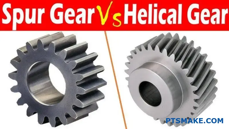
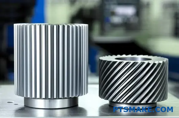
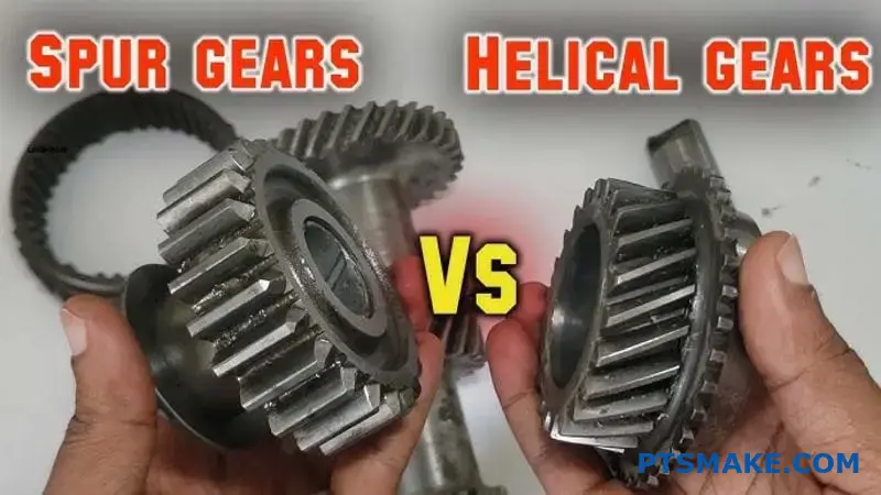
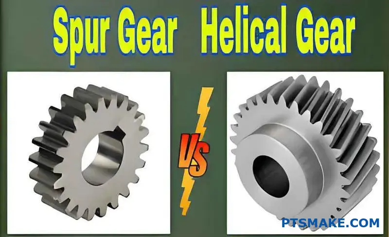
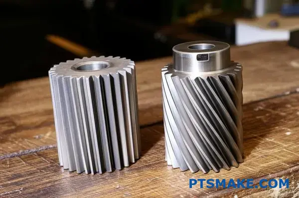
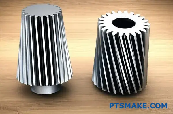
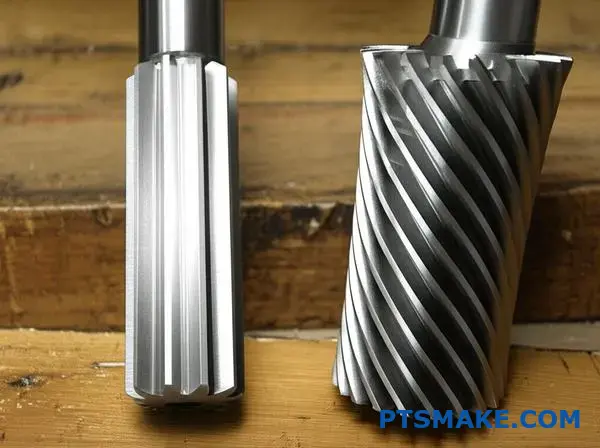
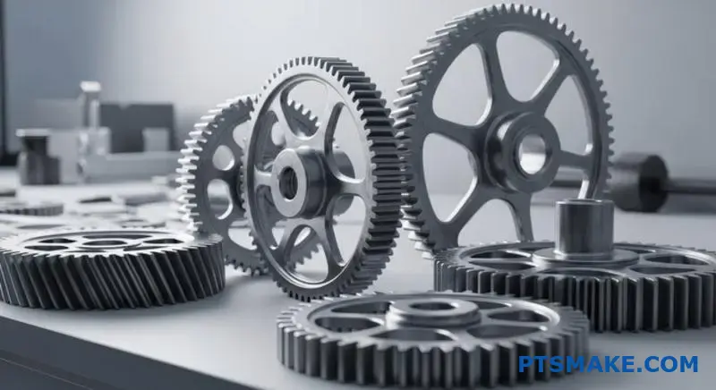
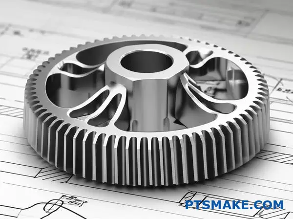
Stirnkuggväxlar har raka kuggar parallellt med axelns axel, medan snedkuggväxlar har vinklade kuggar som skapar en spiral runt kugghjulets omkrets. Denna grundläggande skillnad påverkar allt från ljudnivåer och lastkapacitet till tillverkningskostnader och lagerkrav.
Genom mitt arbete på PTSMAKE har jag hjälpt ingenjörer att navigera i just det här beslutet dussintals gånger. Varje kugghjulstyp har specifika styrkor som gör den idealisk för vissa applikationer. I den här guiden går vi igenom de tekniska skillnaderna, prestandakompromisserna och urvalskriterierna för att hjälpa dig att göra rätt val för ditt projekt.
Vilken är den grundläggande geometrin som definierar en kugghjulstand?
Hemligheten bakom en cylindrisk kuggväxels prestanda är inte bara dess form, utan en mycket specifik kurva. Denna kurva är grunden för dess design.
Den oföränderliga profilen
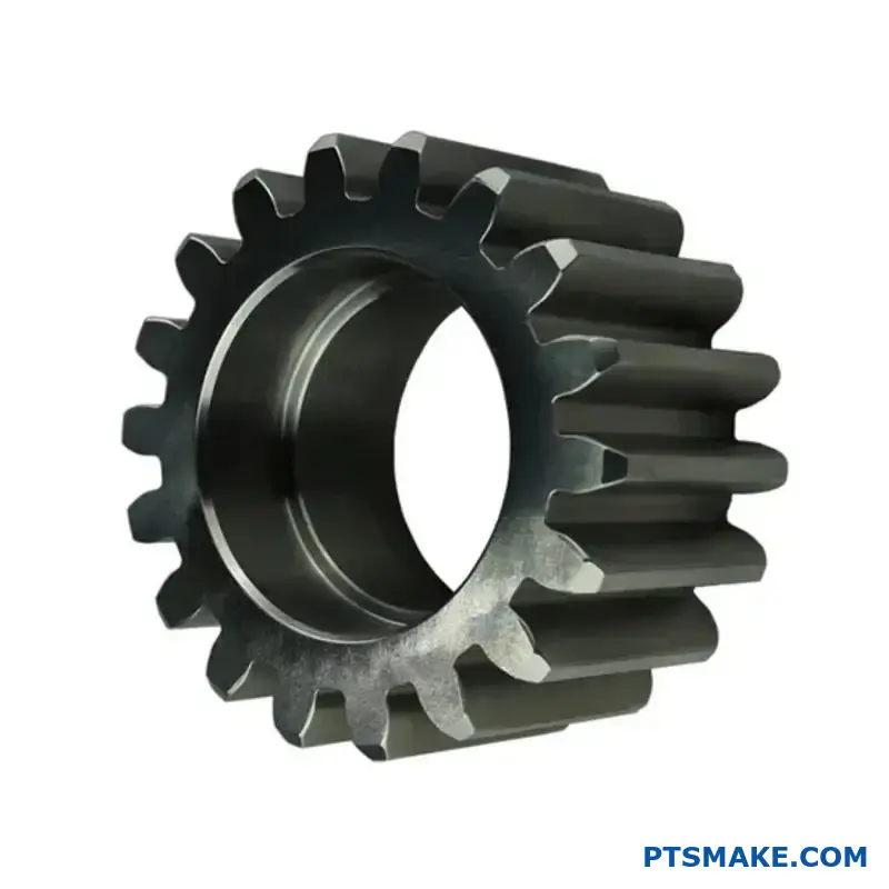
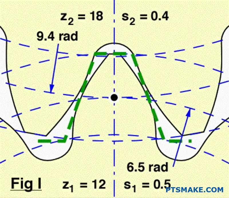
Tandprofilen hos en modern cylindrisk kuggväxel är i grunden en evolverande kurva. Tänk på det som att linda upp ett snöre från en cylinder.
Denna specifika geometri är avgörande. Den säkerställer att rotationshastigheten förblir helt konstant när kugghjulen griper in i varandra. Detta förhindrar skakningar och ojämnt kraftflöde.
| Geometri-funktion | Syfte |
|---|---|
| Involut kurva | Konstant hastighetsförhållande |
| Rak tand | Axiell kraftöverföring |
| Rätt avstånd | Smidigt engagemang |
Hur Involute säkerställer smidig drift
Evolutionsformen är inte godtycklig. Det är en exakt matematisk profil som har utformats av ett enda skäl: att upprätthålla ett konstant hastighetsförhållande mellan kugghjul som griper in i varandra. Detta är en icke förhandlingsbar princip för effektiv kraftöverföring.
Magin i det vanliga normala
När två kugghjulständer kommer i kontakt med varandra passerar den gemensamma normalen (en linje som är vinkelrät mot ytorna vid kontaktpunkten) alltid genom en fast punkt. Denna fasta punkt kallas pitchpunkten.
Denna konsekventa geometri säkerställer att det drivande kugghjulet trycker på det drivna kugghjulet med en jämn hastighet. Det sker inga accelerationer eller retardationer under ingreppet. Detta är en viktig skillnad när man jämför cylindriska kugghjul vs spiralformade kugghjul, eftersom båda är beroende av denna princip för att fungera smidigt.
Involutkurvan genereras från en bascirkel1. Storleken på denna cirkel är grundläggande för den slutliga tandformen och dess prestandaegenskaper. I vårt arbete på PTSMAKE är det avgörande att få rätt geometri för de högprecisionsdelar som våra kunder är beroende av.
| Designaspekt | Konsekvenser av invecklad geometri |
|---|---|
| Kontaktpunkt | Rör sig längs tandytan |
| Handlingslinje | förblir konstant och tangent till båda bascirklarna |
| Hastighetsförhållande | Förblir konstant genom hela maskan |
Evolventkurvan är den grundläggande geometrin för en kugghjulstand. Denna specifika profil är avgörande för att uppnå ett konstant hastighetsförhållande, vilket garanterar en jämn, tillförlitlig och effektiv kraftöverföring mellan kugghjul som griper in i varandra.
Hur förändrar en helixvinkel i grunden en kugghjuls karaktär?
Helixvinkeln är den enskilt viktigaste egenskapen. Den skiljer en spiralformad kuggväxel från en cylindrisk. Det är inte bara en visuell finess.
Spårväxlar har raka tänder. De griper in längs hela sin yta på en gång. Detta skapar en plötslig kontakt linje mot linje.
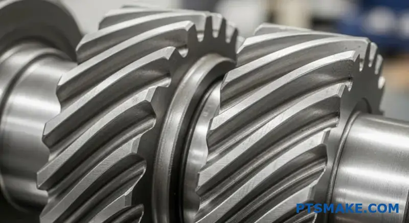
Spiralformade kugghjul, med sina vinklade tänder, griper in på ett annat sätt. Kontakten börjar i ena änden av tanden. Den rör sig sedan smidigt över ytan när kugghjulet roterar.
Detta gradvisa engagemang är nyckeln.
| Funktion | Sporrväxel | Spiralformad kugghjul |
|---|---|---|
| Justering av tänder | Rak | Vinklad (Helix-vinkel) |
| Inledande kontakt | Fullständig linje | Kontaktpunkt |
| Förlovningsstil | Plötsligt | Gradvis och smidig |
Mekanismerna bakom gradvis engagemang
Denna gradvisa ingreppsprocess förändrar allt. Till skillnad från den plötsliga påverkan från kuggväxlar glider spiralformade tänder på plats. Belastningen sker gradvis, inte på en gång. Detta minskar avsevärt stötar och vibrationer.
Resultatet är en mycket tystare drift. Det är en av de främsta anledningarna till att konstruktörer väljer spiralformade kugghjul framför kuggväxlar. I tidigare projekt på PTSMAKE har bytet till spiralformade kugghjul minskat driftsbullret med en märkbar marginal. Detta är avgörande för medicintekniska produkter och konsumentelektronik.
Denna vinklade kontakt skapar dock en bieffekt. Den genererar axiell tryckkraft2, en kraft parallell med kugghjulets axel. Denna kraft finns inte i cylindriska kugghjul och måste hanteras. Korrekt val av lager är avgörande för att hantera denna belastning och förhindra förtida fel.
Kärnan i debatten om kuggväxlar vs spiralformade växlar är denna avvägning.
| Engagemang Aspect | Fördel | Nackdel |
|---|---|---|
| Gradvis kontakt | Mjukare och tystare drift | Skapar axiell dragkraft |
| Vinklade tänder | Högre totalt kontaktförhållande | Kräver robusta lager |
| Lastspridning | Ökad lastkapacitet | Mer komplex tillverkning |
En förändring i lastfördelningen
Den gradvisa inkopplingen innebär också att belastningen fördelas på flera tänder i varje givet ögonblick. Detta står i kontrast till cylindriska kugghjul, där en eller två tänder bär hela belastningen. Denna fördelningsförmåga gör att spiralformade kugghjul klarar större belastningar och har längre livslängd.
Helixvinkeln förändrar i grunden växelkontakten från en abrupt linje till en jämn, progressiv yta. Denna förändring är källan till fördelarna när det gäller buller och lastkapacitet, men innebär också en utmaning i form av axiell dragkraft.
Vilka krafter verkar på en enskild kugghjulstand vid ingrepp?
För att verkligen förstå vad som händer vid kugghjulsingrepp måste vi bryta ner den totala kraften. Denna kraft verkar inte rakt fram. Den verkar i en vinkel mot tandytan.
Ingenjörerna förenklar detta genom att dela upp kraften i två viktiga komponenter. Detta gör analys och konstruktion mycket enklare. Dessa är de tangentiella och radiella krafterna. Var och en har en mycket annorlunda effekt på växelsystemet.
Förståelse av kraftkomponenterna
Här följer en snabb genomgång av dessa två krafter och deras primära roller i ett växelsystem.
| Kraftkomponent | Primär funktion | Viktigaste inverkan |
|---|---|---|
| Tangentiell kraft | Sänder kraft | Skapar vridmoment för att driva lasten |
| Radiell kraft | Separerar kugghjul | Belastar lager och axlar |
Den "arbetande" kraften: Tangentiell komponent
Den tangentiella kraften är den komponent som utför allt nyttigt arbete. Den verkar tangentiellt mot kugghjulets delningscirkel. Det är denna kraft som överför vridmomentet och får den drivna kugghjulet att rotera. När du behöver mer vridmoment har du att göra med en större tangentiell kraft.
Den separerande kraften: Radiell komponent
Den radiella kraften gör däremot ingen nytta för kraftöverföringen. Dess uppgift är att trycka isär de två kugghjulen genom att verka längs en linje som förbinder deras mittpunkter. Denna separerande kraft är en kritisk faktor för konstruktionen. Den belastar axlarna och de lager som bär upp dem direkt.
I tidigare projekt på PTSMAKE har vi sett konstruktioner misslyckas eftersom lagren inte var specificerade för att hantera de radiella belastningarna. Detta är en viktig distinktion i debatten om kuggväxlar och spiralformade kugghjul, eftersom spiralformade kugghjul också medför en axiell kraft (tryckkraft).
Storleken på dessa krafter bestäms av växellådans Tryckvinkel3. En högre vinkel ökar den radiella kraften i förhållande till den tangentiella kraften.
Översikt över kraftriktning
| Kraft | Åtgärdens riktning | Konsekvenser |
|---|---|---|
| Tangentiell | Tangens till pitchcirkeln | Överföring av vridmoment |
| Radiell | Mot växelcentrum | Bärande belastning |
Den totala kraften på en cylindrisk kugghjulskugg förstår man bäst genom dess tangentiella och radiella komponenter. Den tangentiella kraften driver maskinen, medan den radiella kraften skapar belastningar på axlar och lager. Korrekt design tar hänsyn till båda.
Vilken ny kraftkomponent introduceras av spiralformade kugghjul?
Spiralformade kugghjul introducerar en betydande kraftkomponent som inte finns i cylindriska kugghjul: axiell dragkraft. Denna kraft verkar parallellt med kugghjulets axel och skjuter i princip kugghjulet i sidled.
Dess ursprung ligger i kugghjulets vinklade tänder.
En viktig designskillnad
När spiralformade tänder griper in i varandra skapar kontakten en kraft som inte är vinkelrät mot axeln. Detta skapar den axiella komponenten.
| Typ av växel | Primära krafter | Ny styrkekomponent |
|---|---|---|
| Sporrväxel | Radiell, tangentiell | Ingen |
| Spiralformad kugghjul | Radiell, tangentiell | Axiell tryckkraft |
Denna nya kraft kräver noggrann hantering i din design.
Fysiken bakom axiell dragkraft
Helixvinkeln är den direkta orsaken till den axiella dragkraften. När kraft överförs är kraften på tandytan vinkelrät mot själva tanden. Eftersom tanden är vinklad upplöses denna kraft i två huvudkomponenter.
Den ena är den tangentiella kraften, som driver rotationen. Den andra är den axiella kraften, som skjuter längs axeln. Detta är ett centralt begrepp när man jämför cylindriska kugghjul med spiralformade kugghjul. Ju större spiralvinkeln är, desto större blir den axiella kraften för ett givet vridmoment.
Beräkning av effekten
Denna tryckkraft är inte ett litet problem. Den måste motverkas med lämpliga lager, t.ex. koniska rullager eller axiallager. Om man ignorerar detta kan det leda till förtida lagerfel och felinställning av systemet.
Den totala belastningen på tanden skapar en resulterande kraft4 som är en kombination av dessa komponenter. I vårt arbete på PTSMAKE beräknar vi dessa belastningar exakt för att säkerställa att varje komponent vi tillverkar fungerar tillförlitligt i slutmonteringen.
Helix Angles direkta effekt
| Helix-vinkel | Relativ axiell tryckkraft |
|---|---|
| 15° | Låg |
| 30° | Medium |
| 45° | Hög |
Detta förhållande är avgörande för ingenjörer. Att välja en högre spiralvinkel för smidigare drift innebär att man måste hantera större axiella belastningar.
Spiralformade kugghjul ger upphov till en axiell dragkraft på grund av de vinklade kuggarna. Denna kraft är direkt proportionell mot det överförda vridmomentet och tangenten på spiralvinkeln. Korrekt val av lager är avgörande för att hantera denna belastning, en kritisk faktor som saknas i system med cylindriska kugghjul.
Hur definieras ‘kontaktförhållande’ för cylindriska och spiralformade kugghjul?
Kontaktförhållandet är ett viktigt växelmått. Det definierar det genomsnittliga antalet tandpar som är i kontakt vid varje given tidpunkt. Ett högre förhållande innebär att fler tänder delar på belastningen.
Detta resulterar i en smidigare kraftöverföring. Det minskar också buller och vibrationer avsevärt.
Kontaktförhållande för sporre kontra spiralformad kontakt
Utformningen av kugghjulständerna påverkar direkt detta förhållande. Låt oss jämföra dem.
| Typ av växel | Typiskt kontaktförhållande | Engagemang för tand |
|---|---|---|
| Sporrväxel | 1,2 till 1,8 | Sekventiell, ett par kopplar in när ett annat kopplar ur |
| Spiralformad kugghjul | > 2.0 | Överlappande, flera par i kontakt samtidigt |
Denna skillnad är grundläggande för deras prestanda.
Förstå mekaniken bakom kontaktförhållandet
Skillnaden i kontaktförhållande beror på tandgeometrin. Stirnkuggväxlar har raka tänder. Det innebär att kontakten sker längs hela tandytan på en gång. Ingreppet är abrupt.
Spiralformade kugghjul har däremot vinklade tänder. Detta skapar ett gradvis ingrepp. Kontakten börjar i ena änden av tanden och sveper över dess yta när kugghjulet roterar.
Gradvis inkoppling i spiralformade kugghjul
Denna vinklade design förlänger kontaktväg5. Det gör att ett nytt tandpar kan börja koppla in innan det föregående tandparet har kopplat ur helt. Denna överlappning är anledningen till att deras kontaktförhållande alltid är större än 2,0.
Enligt vår erfarenhet på PTSMAKE är detta en avgörande faktor. När kunder diskuterar cylindriska kugghjul vs spiralformade kugghjul För applikationer som kräver låg ljudnivå gör det högre kontaktförhållandet hos spiralformade kugghjul att de ofta är det självklara valet.
Praktiska konsekvenser
Ett högre kontaktförhållande fördelar belastningen över fler tänder. Detta minskar påfrestningarna på enskilda tänder. Det förbättrar lastbärande kapacitet och förlänger kugghjulets livslängd.
| Funktion | Spårväxel (lägre utväxling) | Spiralformad kuggväxel (högre utväxling) |
|---|---|---|
| Lastfördelning | Koncentrerad på 1-2 tandpar | Spridd över 2+ tandpar |
| Bullernivå | Högre | Lägre |
| Vibrationer | Mer uttalad | Smidigare drift |
| Stress på tänderna | Högre | Lägre |
Detta gör spiralformade kugghjul idealiska för höghastighets- och högeffektsapplikationer där jämnhet är avgörande.
Kontaktförhållandet mäter samtidig tandingrepp. Spiralformade kugghjul har ett högre överlappningsförhållande jämfört med cylindriska kugghjul. Detta ger en mjukare och tystare gång och bättre lastfördelning, vilket är en viktig skillnad vid val av växel.
Vilket fysiskt fenomen är den främsta källan till oljud från sporrväxlar?
Problemets kärna är slag. Den primära källan till oljud från kuggväxlar är den plötsliga kollisionen mellan tänderna när de griper in.
Till skillnad från en jämn rullning är detta en plötslig händelse. Denna påverkan skapar en omedelbar tryckspik.
Denna tryckförändring orsakar vibrationer. Dessa vibrationer färdas genom kugghjulsmaterialet och den omgivande luften, vilket våra öron uppfattar som buller.
Processen upprepas med varje enskild tand som griper in i varandra, vilket skapar ett karakteristiskt vinande.
| Steg | Fysisk handling | Resultat |
|---|---|---|
| 1. Förlovning | Tänderna kolliderar plötsligt | Plötslig påverkan |
| 2. Påverkan | Energiöverföring | Kraftig tryckökning |
| 3. Förökning | Spike strålar utåt | Vibration (buller) |
Denna snabba, repetitiva påverkan är det grundläggande fysiska fenomen som vi måste ta itu med.
Mekanismerna bakom ett plötsligt engagemang
Låt oss gräva djupare i denna inverkan. Stirnkuggväxelns tänder möts samtidigt längs hela sin bredd. Denna omedelbara linjekontakt innebär att det inte sker någon gradvis lastöverföring. Det är en allt-eller-inget-händelse.
Denna chockbelastning är grundorsaken. Varje inkoppling fungerar som ett litet hammarslag på systemet och skapar en tryckvåg.
Från vibration till hörbart buller
Denna tryckvåg strålar ut från kugghjulen. När den färdas genom luften uppfattar vi den som ett ljud. Frekvensen på detta ljud är direkt kopplat till hur ofta kuggarna griper in i varandra.
På PTSMAKE ser vi ofta hur denna förlorade energi påverkar effektiviteten, inte bara akustiken. Det ljud du hör är bortkastad energi som skulle kunna användas till nyttigt arbete. En nyckelfaktor är variation i tandstyvhet6 under maskningscykeln, vilket kan förstärka dessa vibrationer.
Detta är en viktig skillnad i debatten om kugghjul och spiralformade kugghjul. Spiralformade kugghjul griper in gradvis över tandytan, vilket avsevärt mildrar denna påverkan.
| Typ av växel | Förlovningsstil | Påverkansnivå | Typiskt brus |
|---|---|---|---|
| Sporrväxel | Omedelbar, fullbredd | Hög | Högt |
| Spiralformad kugghjul | Gradvis, vinklad | Låg | Tystnad |
Våra tester visar att denna grundläggande skillnad i kopplingsmekanik är den främsta orsaken till ljudskillnaderna. Att åtgärda denna påverkan är nyckeln till tystare drift.
Den primära källan till oljud från kuggväxlar är den plötsliga påverkan av tänderna vid inkoppling. Detta skapar plötsliga tryckvariationer och vibrationer. Den plötsliga kontakten är det grundläggande fysiska fenomenet som ger upphov till det karakteristiska kugghjulsljudet.
Varför är spiralformade kugghjul tystare än cylindriska kugghjul?
Det främsta skälet är "gradvis engagemang". Det är ett enkelt koncept som har en enorm inverkan på bullret.
Till skillnad från cylindriska kugghjul är kuggarna i spiralformade kugghjul vinklade. Det innebär att de inte griper in i varandra på en gång.
Hemligheten bakom smidig kontakt
Kontakten börjar på en punkt på tanden. Den sprider sig sedan smidigt över ytan när kugghjulen roterar.
Detta eliminerar den plötsliga påverkan som orsakar buller. Det skapar en mycket mjukare och tystare kraftöverföring.
| Funktion | Sporrväxel | Spiralformad kugghjul |
|---|---|---|
| Engagemang för tand | Plötslig, full bredd | Gradvis, från punkt till linje |
| Påverkansnivå | Hög | Låg |
| Vibrationer | Betydande | Minimal |
Mekaniken bakom tyst drift
Låt oss dyka djupare in i detta. Stirnkuggväxlar griper omedelbart in längs hela tandytan. Denna plötsliga kontakt skapar en chockbelastning, som är den primära källan till växelljud och vibrationer. Det är som att klappa händerna - ett plötsligt, skarpt ljud.
Från påverkan till flöde
Spiralformade kugghjul ändrar denna dynamik helt och hållet. De vinklade kuggarna säkerställer att när en del av en kugg roterar ur ingreppet, så börjar en annan del redan att gripa in. Denna överlappning skapar ett kontinuerligt, oavbrutet kraftflöde.
Denna smidiga övergång mellan tänderna är grundläggande. Det förhindrar de tryckspikar som genererar buller.
Förstå kontaktmönstret
Den kontaktledning7 på en kugghjulstand rör sig diagonalt över dess yta. Denna progressiva in- och urkoppling är det som gör driften så tyst.
På PTSMAKE bearbetar vi dessa vinklar med hög precision. Detta säkerställer att belastningen fördelas jämnt, vilket maximerar både tystnad och växlarnas livslängd. När man överväger kuggväxlar kontra spiralformade kuggväxlar är denna smidiga överföring ofta den avgörande faktorn för våra kunder inom ljudkänsliga områden.
| Karaktäristisk | Sporrväxel | Spiralformad kugghjul |
|---|---|---|
| Lasttillämpning | Plötslig chockbelastning | Gradvis, fördelad belastning |
| Kraftöverföring | Avbruten på tandnivå | Kontinuerlig, smidig |
| Resulterande buller | Högfrekvent "gnäll" | Lågt, stadigt brummande |
De vinklade kuggarna i spiralformade kugghjul möjliggör en gradvis inkoppling. Denna process minimerar de stötar, slag och vibrationer som gör kuggväxlar bullriga. Resultatet är en mycket mjukare och tystare kraftöverföring.
Vilka är de viktigaste prestandakompromisserna mellan dessa två växlar?
Att välja mellan cylindriska och spiralformade kugghjul handlar inte om vilket som är bäst. Det handlar om att förstå de specifika avvägningarna för din applikation. Varje kuggtyp utmärker sig inom olika områden.
Ditt beslut påverkar buller, lastkapacitet, kostnad och komplexitet. En strukturerad jämförelse mellan kuggväxlar och spiralformade kuggväxlar kan klargöra vilket som är det bästa valet. Här är en snabb översikt.
| Funktion | Sporrväxel | Spiralformad kugghjul |
|---|---|---|
| Bullernivå | Högre | Lägre |
| Axiell tryckkraft | Ingen | Nuvarande |
| Kostnad | Lägre | Högre |
| Lastkapacitet | Bra | Utmärkt |
Detta ramverk hjälper till att balansera prestationer mot projektbegränsningar.
För att göra rätt val krävs en djupare titt på dessa prestandaaxlar. Varje beslut innebär en kompromiss som kan påverka din slutprodukt avsevärt. På PTSMAKE guidar vi dagligen våra kunder genom denna process.
Buller vs. axiell tryckkraft
Spiralformade kugghjul är uppskattade för sin tysta drift. De vinklade kuggarna griper in gradvis, vilket minskar det gnisslande ljud som är vanligt med cylindriska kugghjul. Detta gör dem idealiska för konsumentprodukter och biltransmissioner.
Denna vinklade design skapar dock axiell tryckkraft8. Detta är en kraft som är parallell med kugghjulets axel. Den kräver trycklager för att hanteras, vilket gör monteringen mer komplicerad och dyr. Stirnkuggväxlar ger inte upphov till någon sådan kraft.
Enkelhet kontra lastkapacitet
Spårväxlar är enklare att konstruera och tillverka. De raka tänderna gör dem enkla att skära och installera. Denna enkelhet leder till lägre kostnader och enklare underhåll.
Spiralformade kugghjul kan med sin komplexa geometri bära högre belastningar. De vinklade kuggarna ger en större kontaktyta, vilket fördelar belastningen mer effektivt. Detta är en viktig fördel i applikationer med höga vridmoment.
Kostnad kontra jämnhet
Tillverkningsprocessen har en direkt inverkan på kostnaden. Den precisionsslipning som krävs för spiralformade kugghjul gör dem dyrare än cylindriska kugghjul. Denna kostnadsskillnad kan vara betydande vid stora produktionsserier.
I gengäld för den högre kostnaden ger spiralformade kugghjul en exceptionellt jämn och konsekvent kraftöverföring. Denna jämnhet är avgörande för precisionsmaskiner där vibrationer inte är önskvärda.
Effektivitet kontra komplexitet
Stirnkuggväxlar är mycket effektiva och når ofta upp till 98-99%. Deras rullande kontakt genererar mycket lite friktion.
Spiralformade kugghjul medför en glidande rörelse mellan kuggarna, vilket kan minska effektiviteten något på grund av friktion. Detta är dock ofta en liten kompromiss mot deras överlägsna prestanda på andra områden.
Valet mellan cylindriska och spiralformade kugghjul är en balansgång. Dina prioriteringar - låg ljudnivå, hög lastkapacitet, budget eller enkel design - avgör vilken växel som är idealisk. Det finns inte ett enda "bästa" svar, bara det som passar bäst för din specifika applikation.
Hur förhåller sig lastbärande kapacitet mellan cylindriska och spiralformade kugghjul?
När man jämför kuggväxlar med spiralformade kugghjul av samma storlek och material, vinner spiralformade kugghjul konsekvent på lastbärande kapacitet. Detta är inte heller med en liten marginal.
Skillnaden kommer från deras grundläggande design. Stirnkuggväxlar griper in plötsligt över hela kuggytan på en gång.
Spiralformade kugghjul med vinklade kuggar kopplas in gradvis. Denna mjukare övergång fördelar belastningen mer effektivt, vilket möjliggör högre prestanda under identiska förhållanden.
| Typ av växel | Typisk lastkapacitet | Nyckelfaktor |
|---|---|---|
| Sporrväxel | Lägre | Omedelbar kontakt med hela ansiktet |
| Spiralformad kugghjul | Högre | Gradvis, distribuerad kontakt |
Mekaniken bakom högre kapacitet
Den överlägsna lastkapaciteten hos spiralformade kugghjul beror på två viktiga mekaniska fördelar. Det är ett koncept som vi ofta förklarar för våra kunder på PTSMAKE när de ska välja rätt kugghjul för krävande applikationer.
Gradvis engagemang och lastfördelning
Till skillnad från den plötsliga belastningen på kuggarna i en cylindrisk kuggväxel, glider kuggarna i en spiralformad kuggväxel i kontakt med varandra. Belastningen appliceras gradvis, med början i ena änden av tanden och rör sig över dess yta.
Detta innebär att flera tänder ofta är i kontakt samtidigt och delar på den totala belastningen. Detta ökade kontaktförhållande minskar påfrestningen på varje enskild tand avsevärt. Fördelningen av Hertzian kontaktspänning9 är mycket mer effektivt.
Förklaringar till ökat kontaktförhållande
Kontaktförhållandet är ett mått på hur många tänder som är i ingrepp vid varje given tidpunkt. Ett högre kontaktförhållande innebär bättre lastfördelning och jämnare drift. I våra tester uppvisar spiralformade kugghjul ett betydligt högre kontaktförhållande.
| Funktion | Sporrväxel | Spiralformad kugghjul |
|---|---|---|
| Engagemang för tand | Plötsligt, allt på en gång | Gradvis, progressiv |
| Lastfördelning | Koncentrerad på ett tandpar | Delas mellan flera tänder |
| Typiskt kontaktförhållande | 1,1 till 1,7 | 2,0 eller högre |
| Resulterande stress | Hög toppbelastning | Lägre, fördelad belastning |
Denna fördelning gör att kuggväxlarna kan hantera större vridmoment och kraft utan att öka risken för fel på grund av böjutmattning eller ytpitting.
Spiralformade kugghjul har högre lastbärande kapacitet än cylindriska kugghjul tack vare de vinklade kuggarna. Denna konstruktion ger ett högre kontaktförhållande och en gradvis lastapplicering, vilket fördelar belastningen över flera kuggar och resulterar i en jämnare och mer robust kraftöverföring under identiska förhållanden.
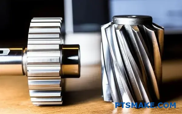
Hur står sig tillverkningskostnader och komplexitet i jämförelse?
När man jämför kuggväxlar med spiralformade kuggväxlar är tillverkningen den största kostnadsdrivande faktorn. Skillnaden handlar om geometri.
Enkelheten hos sporrväxlar
Spårkugghjul har raka tänder. Denna enkla konstruktion gör dem mycket enklare att tillverka. Vi kan använda standardprocesser som hobbning eller formning.
Hela tanden kan skäras i en enda passage. Detta leder till snabbare cykeltider och lägre kostnader.
Komplexiteten hos spiralformade kugghjul
Spiralformade kugghjul har vinklade tänder. Denna vinkel medför komplexitet. Tillverkningen kräver mer exakta maskinuppställningar och specialverktyg för att skapa spiralformen.
| Typ av växel | Enkel tillverkning | Typisk process |
|---|---|---|
| Sporrväxel | Hög | Fräsning, formning |
| Spiralformad kugghjul | Måttlig | Specialiserad hobbning |
Denna komplexitet leder direkt till längre bearbetningstider och högre produktionskostnader.
Tillverkningsprocessen i sig berättar historien om kostnaden. För många av våra kunder på PTSMAKE är det viktigt att förstå detta för att kunna budgetera sina projekt på ett effektivt sätt.
Djupdykning i bearbetningsmetoder
Maskinbearbetning av sporrhjul
Tillverkning av kugghjul är en mycket direkt process. Vi använder ofta en hobbingsmaskin. Skärverktyget, eller hobben, och kugghjulsämnet roterar tillsammans. Fräsen skär de raka tänderna på ett effektivt sätt.
Den här processen är mycket automatiserad och snabb. Den kräver mindre komplexa inställningar, vilket minimerar arbets- och maskintid. Detta är en viktig anledning till deras kostnadseffektivitet.
Maskinbearbetning av spiralformade kugghjul
Att tillverka spiralformade kugghjul är mer komplicerat. Maskinen måste skära tänderna i en specifik spiralvinkel. Detta kräver en synkroniserad, spiralformad rörelse mellan fräsen och kugghjulsämnet.
Denna process skapar också betydande axiell tryckkraft10, vilket kräver robusta maskininställningar för att bibehålla precisionen. Uppställningen är mer tidskrävande och skärhastigheterna är ofta lägre för att säkerställa noggrannheten.
| Funktion | Maskinbearbetning av sporrhjul | Maskinbearbetning av spiralformade kugghjul |
|---|---|---|
| Verktygsväg | Rak, parallell med axeln | Vinklad, spiralformad bana |
| Maskininställning | Enklare, snabbare | Mer komplex, kräver vinkelsynkronisering |
| Cykeltid | Kortare | Längre |
| Verktyg | Standard spishäll | Vinkelspecifik fräs |
| Associerade styrkor | Främst radiella krafter | Radiala och axiella krafter |
Varje steg tar längre tid och kräver större kunskaper hos operatören, vilket ökar den slutliga kostnaden per detalj.
Stirnkuggväxlar är billigare och snabbare att tillverka på grund av sin enkla geometri med raka kuggar. Spiralformade kugghjul, med sina vinklade tänder, kräver mer komplexa bearbetningsuppställningar, specialverktyg och längre cykeltider, vilket driver upp tillverkningskostnaderna.
Vilka typer av lagerarrangemang behövs för varje växeltyp?
Att välja rätt lager är avgörande. Det har en direkt inverkan på växelsystemets prestanda och livslängd. Den primära skillnaden handlar om de krafter som varje växeltyp genererar.
Behov av lager för sporrväxel
Stirnkugghjul har raka tänder. På grund av detta ger de huvudsakligen upphov till radiella belastningar. Detta förenklar valet av lager. Lagren behöver bara stödja axeln mot dessa utåtriktade krafter.
Behov av lager för spiralformade kugghjul
Spiralformade kugghjul med vinklade tänder är mer komplexa. De genererar både radiella och betydande axiella belastningar. Detta kräver ett mer robust lagerarrangemang för att hantera krafter från flera håll.
En snabb jämförelse av cylindriska kugghjul vs spiralformade kugghjul belastningar är nedan.
| Typ av växel | Primär belastning | Sekundär belastning |
|---|---|---|
| Sporrväxel | Radiell | Minimal |
| Spiralformad kugghjul | Radiell | Axiell (tryckkraft) |
Djupdykning i val av lager
Belastningsegenskaperna för varje kugghjulstyp bestämmer lagerarrangemanget. Det är ett grundläggande koncept som vi alltid betonar i våra designkonsultationer på PTSMAKE. Om man gör fel leder det till för tidiga fel.
Lager för cylindriska kugghjul
För cylindriska kugghjul ligger fokus på att hantera radiella krafter. Enkla lagertyper fungerar ofta bra.
Spårkullager är ett vanligt val. De är kostnadseffektiva och hanterar radiella belastningar på ett effektivt sätt. I vissa applikationer med högre belastning kan cylindriska rullager användas för större radiell kapacitet.
Lager för spiralformade kugghjul
Spiralformade kugghjul är annorlunda. Tändernas spiralformade vinkel skapar en kontinuerlig tryckkraft längs axelns axel. Denna kraft är känd som axiell tryckkraft11.
Denna kombinerade belastningsprofil kräver mer avancerade lösningar. Ett enda spårkullager är oftast inte tillräckligt.
Vi rekommenderar ofta koniska rullager. De är konstruerade för att hantera tunga radiella och axiella belastningar samtidigt. Att placera dem i par (rygg mot rygg eller ansikte mot ansikte) är en standardmetod för att motverka tryck i båda riktningarna.
Här är en guide för val av lager.
| Typ av växel | Vanlig lagertyp | Anledning |
|---|---|---|
| Sporrväxel | Spårkullager med djup spårning | Utmärkt för radiella belastningar, kostnadseffektivt. |
| Spiralformad kugghjul | Lager för koniska rullar | Klarar kombinerade radiella och höga axiella belastningar. |
Kort sagt kräver kuggväxlar lager för radiella belastningar. Spiralformade kugghjul behöver robusta system, som koniska rullager, för att hantera både betydande radiella och axiella krafter. Rätt val är nyckeln till växellådans tillförlitlighet och långsiktiga prestanda.
I vilka applikationer är kuggväxlar det bästa valet?
Stirnkuggväxlar är utmärkta där enkelhet och kostnad är avgörande. De är arbetshästarna för okomplicerad kraftöverföring mellan parallella axlar.
Konstruktionen eliminerar axiella dragkrafter, vilket förenklar lagerkraven och huskonstruktionen. Detta gör dem idealiska för många maskiner.
Viktiga urvalskriterier
Kostnadseffektivitet
Spårkugghjul är i allmänhet billigare att tillverka än spiralformade kugghjul. Detta är en viktig faktor vid produktion av stora volymer.
Enkelhet i design
Deras enkla geometri gör dem lätta att konstruera och installera. På PTSMAKE kan vi bearbeta dem till exakta toleranser på ett effektivt sätt.
| Funktion | Sporrväxlar | Spiralformade kugghjul |
|---|---|---|
| Kostnad | Lägre | Högre |
| Axiell tryckkraft | Ingen | Nuvarande |
| Axeluppriktning | Endast parallell | Parallell och vinkelrät |
| Bullernivå | Högre | Lägre |
Djupdykning i applikationen
Valet i debatten om cylindriska kugghjul kontra spiralformade kugghjul handlar ofta om den specifika applikationens krav. Stirnkuggväxlar är inte bara ett budgetalternativ; de är det tekniskt överlägsna valet i vissa scenarier. Deras direkta och effektiva kraftöverföring är oslagbar för enkla system.
Enkla transmissioner
Tänk på tvättmaskiner eller mixrar. Dessa enheter behöver tillförlitlig överföring av vridmoment utan komplexiteten eller kostnaden för mer avancerade växelsystem. Spårväxlar ger detta perfekt. De får jobbet gjort på ett effektivt sätt och håller slutprodukten överkomlig för konsumenterna.
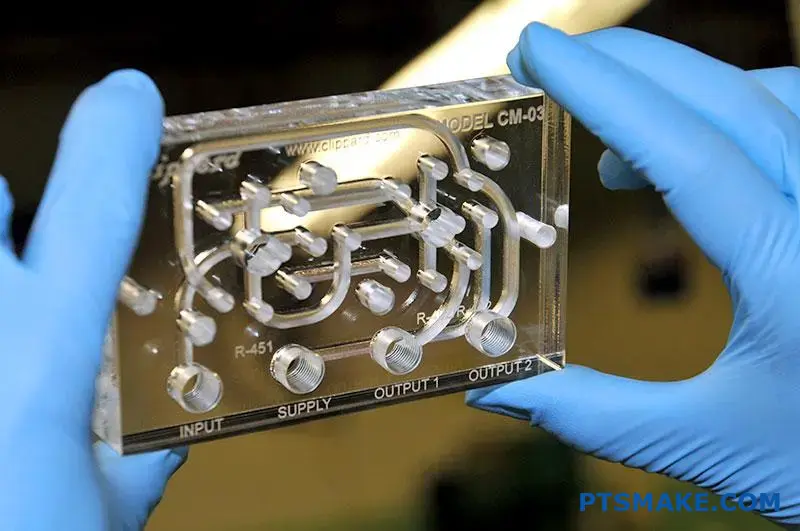
Positiva deplacementspumpar
Enligt vår erfarenhet från kunder inom flödesindustrin är precision inte förhandlingsbart. Pumpar som använder kugghjul som griper in i varandra, så kallade kugghjulspumpar, förlitar sig på den konstanta volymöverföring som skapas av kugghjulständerna. Konstruktionen säkerställer ett jämnt, icke-pulserande flöde, vilket är avgörande för hydraulsystem. Kugghjulen måste vara exakta, en tjänst som vi på PTSMAKE är specialiserade på genom CNC-bearbetning. Det här är ett klassiskt fall där den enkla geometrin hos en kuggväxel överträffar en komplex geometri.
Transportörsystem
Transportband i fabriker eller lagerlokaler behöver en jämn och tillförlitlig rörelse. De arbetar i måttliga hastigheter där buller är ett mindre problem. Stirnkuggväxlar ger det vridmoment som krävs för att driva banden utan den extra kostnad och komplexitet som uppstår vid axiella belastningar. Deras hållbarhet garanterar lång livslängd med minimalt underhåll. Detta är avgörande för att hålla produktionslinjerna igång smidigt.
| Tillämpning | Primärt skäl för val av sporrväxel |
|---|---|
| Tvättmaskin | Låg kostnad, enkelhet |
| Kugghjulspumpar | Exakt Positiv förskjutning12, Ingen axiell tryckkraft |
| Transportörbälten | Tillförlitlighet, kostnadseffektivitet |
| Elverktyg | Hög vridmomentöverföring, enkel montering |
Spårväxlar är det överlägsna valet för applikationer där enkelhet, kostnadseffektivitet och avsaknad av axiell dragkraft är avgörande. De utmärker sig i enkla kraftöverföringssystem som enkla transmissioner, pumpar och transportörer, och erbjuder tillförlitlighet och enkelt underhåll.
I vilka applikationer är spiralformade kugghjul det självklara valet?
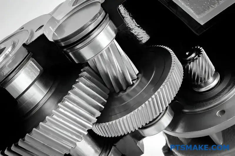
När prestanda inte kan kompromissas är spiralformade kugghjul det enda valet. Deras design är perfekt för applikationer som kräver jämn och tyst kraftöverföring. Tänk på höghastighetsmiljöer med hög belastning.
Stirnkuggväxlar kan helt enkelt inte konkurrera här. Den gradvisa inkopplingen av de spiralformade tänderna minskar buller och vibrationer. Detta gör dem nödvändiga i vissa branscher.
Högpresterande applikationer
Transmissioner för bilar
I bilar, särskilt elfordon, är bullerdämpning av avgörande betydelse. Spiralformade kugghjul säkerställer en tyst och smidig färd för passagerarna.
Industriella växellådor
För tunga maskiner och turbiner är tillförlitlighet nyckeln. Spiralformade kugghjul klarar högre belastningar och hastigheter, vilket ger långsiktig driftsstabilitet.
| Tillämpning | Viktiga krav | Varför spiralformade kugghjul? |
|---|---|---|
| Fordon | Tyst drift | Vinklade tänder minskar buller och vibrationer. |
| Turbiner | Höghastighetseffekt | Smidig inkoppling klarar höga varvtal. |
| Industriell | Hög lastkapacitet | Större tandkontakt fördelar påfrestningarna. |
I debatten om kuggväxlar kontra spiralformade kugghjul är det tillämpningen som avgör vem som vinner. Stirnkuggväxlar är effektiva och enklare att tillverka, men de är bullriga vid höga hastigheter. Detta beror på den plötsliga kontakten mellan tänderna.
Spiralformade kugghjul löser detta problem. De vinklade tänderna griper in gradvis över hela kugghjulets yta. Detta skapar en mycket mjukare och tystare kraftöverföring. Våra tester på PTSMAKE visar konsekvent en betydande minskning av buller, vibrationer och hårdhet (NVH).
Den tekniska avvägningen
Denna smidiga funktion har en nackdel. De vinklade tänderna producerar axiell tryckkraft13, En kraft som trycker isär kugghjulen längs deras axlar. Denna kraft måste hanteras med lämpliga lager, t.ex. trycklager.
Detta gör konstruktionen mer komplicerad och kostsam. För applikationer där prestanda är av största vikt är det dock ett nödvändigt tekniskt beslut. Om man ignorerar detta kan det leda till för tidiga fel.
Applikationsspecifika fördelar
| Funktion | Förmåner inom fordonsindustrin | Förmån för industrin |
|---|---|---|
| Smidigt engagemang | Förbättrad körkomfort. | Minskat slitage på maskiner. |
| Kapacitet för höga hastigheter | Lämplig för moderna motorer och elbilar. | Oumbärlig för turbiner för kraftproduktion. |
| Större lastkapacitet | Ökad tillförlitlighet i överföringen. | Längre livslängd för växellådor med hög belastning. |
På PTSMAKE vägleder vi våra kunder genom dessa avvägningar. Vi hjälper dem att välja rätt växeltyp och utforma stödsystemen för att säkerställa optimal prestanda och hållbarhet för deras specifika applikation.
För höghastighetssystem med hög effekt, t.ex. transmissioner i fordon och industriella turbiner, är spiralformade kugghjul ett måste. Deras konstruktion säkerställer en jämn och tyst drift, trots den extra komplexiteten i hanteringen av axiell dragkraft. Stirnkuggväxlar är helt enkelt för bullriga för dessa krävande applikationer.
Hur skiljer sig smörjstrategin åt mellan sporr- och snedkuggväxlar?
Alla kugghjul behöver smörjas, men valet av smörjmedel är inte detsamma för alla. Strategin skiljer sig avsevärt när man jämför cylindriska kugghjul med spiralformade kugghjul.
Spårväxlar fungerar ofta bra med universalsmörjmedel. Deras raktandade design resulterar främst i rullande kontakt. Detta innebär mindre friktion och värmeutveckling.
Spiralformade kugghjul ger dock en mer glidande rörelse. Detta beror på de vinklade kuggarna. Denna glidning kan skapa högre tryck och temperaturer vid kontaktpunkterna.
Viktiga faktorer för smörjmedel
| Typ av växel | Primär kontakt | Krav på smörjmedel |
|---|---|---|
| Sporrväxel | Rullande | Allmänna ändamål, lägre viskositet |
| Spiralformad kugghjul | Glidning och rullning | Högre viskositet, EP-tillsatser |
Denna distinktion är avgörande för den långsiktiga utvecklingen.
Rollen för additiv för extrema tryck
Glidningen i spiralformade kugghjul är den främsta orsaken till olika smörjbehov. Denna glidning under belastning skapar en utmaning som standardsmörjmedel inte alltid kan hantera. Den genererar betydande friktionsvärme.
Denna värme kan bryta ner oljefilmen mellan tänderna. När denna film brister uppstår metall-mot-metall-kontakt, vilket leder till nötning och förtida slitage. Det här är ett vanligt fel som vi har sett i applikationer med hög belastning.
För att förhindra detta behöver smörjmedel för spiralformade kugghjul ofta särskilda tillsatser. Det är här som smörjmedel med specifika Additiv för extremt tryck (EP)14 blir icke förhandlingsbara.
När är EP-additiv nödvändiga?
Baserat på våra tester med kunder blir behovet av EP-additiv tydligt under specifika förhållanden.
| Driftförhållanden | Smörjmedel för sporrväxel | Smörjmedel för spiralformade kugghjul |
|---|---|---|
| Låg hastighet, låg belastning | Standard växellådsolja | Standard växellådsolja |
| Hög hastighet, hög belastning | Standard växellådsolja | Olja med EP-tillsatser |
| Stötbelastning | Kan behöva mild EP | Kräver robusta EP-additiv |
Dessa tillsatser bildar ett skyddande kemiskt skikt på växellådans yta. Detta skikt fungerar som en sista försvarslinje när oljefilmen är skadad. Det förhindrar att kuggtänderna svetsas samman under intensivt tryck. På PTSMAKE granskar vi alltid driftsbelastningarna för att rekommendera rätt smörjmedelsstrategi.
Båda växeltyperna kräver smörjning, men de högre glidkrafterna i spiralformade kugghjul kräver ofta smörjmedel med EP-tillsatser. Detta val är avgörande för att förhindra slitage och säkerställa drivlinans tillförlitlighet, särskilt under tunga belastningar.
Hur är känsligheten för växeljustering jämfört mellan de två?
Kugghjulsuppriktning är avgörande för prestanda och livslängd. Även en liten felinställning kan orsaka stora problem.
Spiralformade kugghjul är i allmänhet mer känsliga för detta. De vinklade kuggarna kräver exakt positionering.
Utan den fördelas inte belastningen jämnt. Detta leder till buller, vibrationer och förtida fel. Låt oss undersöka varför detta händer.
| Typ av växel | Inriktning Känslighet | Primär orsak |
|---|---|---|
| Sporrväxlar | Mindre känslig (för parallellkoppling) | Full linjekontakt längs tandytan. |
| Spiralformade kugghjul | Mer känslig | Vinklad kontakt kräver perfekt axelparallellitet. |
Den kritiska karaktären hos axeluppriktning
I alla växelsystem är perfekt axeluppriktning målet. I verkligheten finns det dock alltid små avvikelser. Hur varje kugghjulstyp hanterar denna imperfektion är en nyckelfaktor i debatten om cylindriska kugghjul kontra spiralformade kugghjul.
Förklaring av känsligheten hos spiralformade kugghjul
Spiralformade kugghjul uppnår sin jämna och tysta gång genom gradvis tandingrepp. Kontakten börjar i ena änden av tanden och rör sig över dess yta.
Denna gradvisa kontakt är en styrka men också en svaghet. Om axlarna är felriktade koncentreras belastningen på en del av tanden. Detta skapar lokaliserade tryckpunkter, eller spänningskoncentration15, vilket leder till snabbare slitage och gropfrätning.
I vårt arbete på PTSMAKE har vi sett kuggväxlar som havererat tidigt på grund av mindre monteringsfel. Det ojämna slitmönstret som uppstår är ett tydligt tecken på uppriktningsproblem.
| Typ av felinställning | Påverkan på spiralformade kugghjul | Påverkan på sporrväxlar |
|---|---|---|
| Parallell | Hög. Gör att belastningen koncentreras till tandändarna. | Måttlig. Linjekontakten upprätthålls fortfarande, men ojämnt. |
| Angular | Mycket hög. Ändrar kontaktmönster och belastning drastiskt. | Hög. Leder till kantbelastning och hög stress. |
Förlåtelse för sporrväxel
Stirnkuggväxlar med sina raka kuggar är mer förlåtande mot en liten snedställning av den parallella axeln. Belastningen fördelas över hela kuggytan.
Även om de inte är immuna kan de tolerera mindre defekter bättre utan att omedelbart drabbas av katastrofala fel. Vinkelfelinställning är dock fortfarande mycket skadligt.
Sammanfattningsvis kräver spiralformade kugghjul högre precision vid montering. Deras konstruktion, som ger en jämn drift, gör dem också mer känsliga för felinställning. Stirnkuggväxlar erbjuder större tolerans, särskilt för avvikelser i parallella axlar, vilket gör dem mer robusta i vissa applikationer.
Hur begränsar drifthastigheten deras respektive användningsområden?
Drifthastigheten är en kritisk faktor när man ska välja mellan cylindriska och spiralformade kugghjul. Det påverkar direkt buller, vibrationer och de dynamiska belastningarna i ett system.
För cylindriska kugghjul finns det en praktisk hastighetsgräns. Konstruktionen med raka tänder orsakar en plötslig kontakt i hela linjen vid ingreppet. Detta skapar slagkrafter som eskalerar med hastigheten.
Detta är en viktig faktor i debatten om kuggväxlar kontra snedställda kuggväxlar. Nedan följer en snabb jämförelse av deras hastighetsrelaterade egenskaper.
| Funktion | Sporrväxlar | Spiralformade kugghjul |
|---|---|---|
| Lämplig hastighet | Låg till måttlig | Hög |
| Buller vid hög hastighet | Hög | Låg |
| Påverkan på maskning | Betydande | Minimal |
Denna plötsliga inkoppling är anledningen till att kuggväxlar blir bullriga och vibrerar vid högre hastigheter.
Utmaningen med hastighet med cylindriska kugghjul
Kärnproblemet med cylindriska kugghjul i höga hastigheter är deras geometri. Hela tandytan griper in på en gång. Tänk på det som en liten, snabb hamrande effekt. När kugghjulet snurrar snabbare blir dessa slag mer frekventa och kraftfulla.
Detta genererar betydande dynamiska belastningar16, vilket belastar kuggarna och skapar hörbart ljud. Över en viss rotationshastighet kan denna vibration äventyra hela systemets tillförlitlighet och prestanda. Detta skapar effektivt en praktisk hastighetsgräns för deras användning.
Varför spiralformade kugghjul är utmärkta vid höga hastigheter
Spiralformade kugghjul övervinner denna begränsning på ett elegant sätt. De vinklade kuggarna gör att kontakten börjar i ena änden av kuggen och sedan går smidigt över hela kuggytan. Detta gradvisa ingrepp eliminerar de slagkrafter som är karakteristiska för cylindriska kugghjul.
Den smidiga ingreppsmekanismen ger tystare drift och betydligt mindre vibrationer. I de projekt vi hanterar på PTSMAKE gör denna kvalitet spiralformade kugghjul till standardvalet för applikationer som kräver höga rotationshastigheter, som i fordonsväxellådor eller industriella precisionsmaskiner.
| Hastighetsområde | Rekommenderad växeltyp | Nyckel Motivering |
|---|---|---|
| Låg till måttlig | Sporrväxel | Enkelhet och kostnadseffektivitet. |
| Hög | Spiralformad kugghjul | Smidig, tyst drift och tillförlitlighet. |
Denna grundläggande skillnad i engagemang är det som skiljer deras applikationsområden åt.
Stirnkuggväxlar är hastighetsbegränsade på grund av slagkrafterna och bullret från deras plötsliga kuggingrepp. Spiralformade kugghjul, med sin gradvisa ingrepp, arbetar mjukt och tyst, vilket gör dem viktiga för höghastighetsapplikationer där tillförlitlighet och låg ljudnivå är avgörande.
Hur väljer man rätt växeltyp för en viss applikation?
Att välja rätt utrustning innebär en strukturerad process. Det handlar inte bara om en enda specifikation. Du måste balansera flera nyckelfaktorer.
Detta säkerställer att det slutliga valet uppfyller alla prestandamål. Jag börjar alltid med de primära applikationskraven.
Viktiga faktorer för beslutsfattandet
Ett tydligt ramverk förhindrar kostsamma misstag. Tänk på dessa fem kritiska områden innan du fattar ett beslut. Var och en av dem påverkar utrustningens lämplighet.
| Faktor | Beskrivning |
|---|---|
| Varvtal (RPM) | Den operativa rotationshastighet som krävs. |
| Vridmoment | Den rotationskraft som växeln måste överföra. |
| Bullernivå | Den acceptabla ljudnivån under drift. |
| Budget | Kostnadsbegränsningar för komponenten. |
| Utrymmesbegränsningar | Det fysiska utrymme som är tillgängligt för växelsystemet. |
Ett steg-för-steg-urvalssystem
På PTSMAKE guidar vi våra partners genom en systematisk process. Den börjar med att definiera de primära kraven. Detta säkerställer att rätt växel väljs för både prestanda och tillverkningsbarhet.
En vanlig utgångspunkt är valet mellan kuggväxlar och spiralformade kuggväxlar. Stirnkuggväxlar är effektiva och kostnadseffektiva för måttliga hastigheter. Spiralformade kugghjul är mjukare och tystare, vilket gör dem idealiska för höghastighetsapplikationer eller applikationer som är känsliga för buller.
Men beslutet är sällan så enkelt. Du måste ta hänsyn till hur olika växeltyper presterar i förhållande till alla kriterier. Precisionsapplikationer medför också faktorer som motreaktion17, vilket kan vara kritiskt.
Beslutsmatris för val av växel
Vi använder ofta en beslutsmatris med våra kunder. Det här verktyget hjälper till att visualisera avvägningarna mellan olika redskapstyper. Det ger en tydlig, datadriven väg till den bästa lösningen.
| Typ av växel | Hastighetsklassning | Vridmomentkapacitet | Bullernivå | Relativ kostnad | Effektivitet |
|---|---|---|---|---|---|
| Sporre | Medium | Medium | Hög | Låg | Mycket hög |
| Helix | Hög | Hög | Låg | Medium | Hög |
| Avfasning | Medium | Medium | Medium | Hög | Hög |
| Mask | Låg | Mycket hög | Mycket låg | Medium | Låg-Medium |
Denna matris är en startpunkt. Din specifika applikation avgör vilken balans som är rätt.
En strukturerad beslutsram förenklar valet av växlar. Genom att utvärdera krav som hastighet, vridmoment, buller, budget och utrymme kan du systematiskt identifiera den optimala växeltypen för dina specifika behov, undvika gissningar och säkerställa tillförlitlig prestanda.
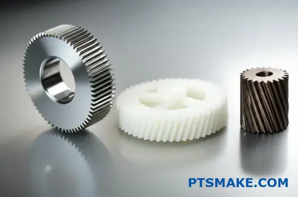
Hur väljer man rätt material till en växel?
Att välja rätt kuggmaterial är ett kritiskt beslut. Det har en direkt inverkan på produktens prestanda, livslängd och totalkostnad. Din applikations specifika krav måste styra ditt val.
Tänk på faktorer som belastning, hastighet och driftsmiljö. En stålväxel med högt vridmoment i en fordonsväxellåda har helt andra behov än en plastväxel med låg ljudnivå i en kontorsskrivare.
Här är en snabb översikt för att komma igång:
| Materialkategori | Viktig fördel | Vanliga användningsfall |
|---|---|---|
| Stållegeringar | Hög hållfasthet och hållbarhet | Transmissioner för bilar |
| Plast | Lågt buller och korrosionsbeständighet | Kontorsutrustning, medicinsk |
| Bronslegeringar | Låg friktion och följsamhet | Snäckväxeldrivningar |
Den här guiden hjälper dig att navigera bland dessa alternativ för ditt projekt.
Låt oss dyka djupare in i en praktisk guide för materialval. Det bästa valet balanserar alltid prestanda med budget. På PTSMAKE börjar vi ofta med att analysera de operativa styrkorna och miljön för att hitta denna balans.
Stållegeringar för högbelastade jobb
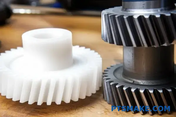
För hög hållfasthet och hållbarhet är stål det bästa materialet. Det klarar höga belastningar och slitage exceptionellt bra, oavsett om det gäller kuggväxlar eller spiralformade kugghjul. Värmebehandling kan också förbättra dess egenskaper avsevärt.
| Stållegering | Bäst för | Viktig funktion |
|---|---|---|
| 4140 stål | Högt vridmoment och seghet | Förmåga till genomhärdning |
| 8620 Stål | Slag och ytförslitning | Utmärkt för sätthärdning |
Plaster för specialiserade tillämpningar
Underskatta inte plast. De löser vanliga problem som buller, korrosion och behovet av extern smörjning. Baserat på våra tester är de idealiska för applikationer med lättare belastning där dessa faktorer är kritiska.
Den unika tribologiska egenskaper18 av plast gör dem viktiga i många moderna konstruktioner.
Populära plastalternativ
- Delrin (Acetal): Känd för sin låga friktion och utmärkta dimensionsstabilitet. Vi rekommenderar den för rörliga delar med hög precision.
- Nylon: Ger god seghet och kemikaliebeständighet. Det är också fantastiskt bra på att dämpa buller och vibrationer.
Brons för lågfriktionsmatning
Bronslegeringar är ett klassiskt val för vissa kugghjulstyper. De är särskilt vanliga för snäckhjul som passar ihop med stålsnäckor. Denna materialkombination ger mycket låg friktion och förhindrar gnissling under tunga belastningar.
Att välja rätt kugghjulsmaterial är en avvägning. Stål ger styrka för höga belastningar. Plast erbjuder tyst, korrosionsbeständig drift för lättare uppgifter. Brons utmärker sig i specifika applikationer med låg friktion. Nyckeln är att matcha materialet med de unika kraven i din applikation.
Hur skulle du konstruera om en bullrig kuggväxel så att den blir tystare?
En bullrig kuggväxel är en vanlig utmaning för ingenjörer. Den mest effektiva lösningen innebär ofta en fullständig omkonstruktion. Att bara byta ut delar är inte tillräckligt.
Vi ersätter de bullriga cylindriska kugghjulen med spiralformade kugghjul. Denna förändring minskar bullret avsevärt. Det kräver dock en noggrann omkonstruktion av hela systemet.
Det gäller att förstå skillnaderna mellan cylindriska kugghjul och spiralformade kugghjul. De vinklade kuggarna i spiralformade kugghjul griper in gradvis, vilket är anledningen till att de går tystare.
| Typ av växel | Engagemang | Bullernivå |
|---|---|---|
| Sporrväxel | Plötsligt | Hög |
| Spiralformad kugghjul | Gradvis | Låg |
Denna omkonstruktion omfattar modifieringar av geometri, lager och hölje.
När vi konstruerar om en frekvensomriktare för att få den tystare går vi längre än ett enkelt växelbyte. Övergången från cylindriska kugghjul till spiralformade kugghjul är en grundläggande teknisk förändring. Det påverkar hela den mekaniska enheten.
Omberäkning av växelgeometri
Det första steget är att räkna om växelgeometrin. Införandet av en helixvinkel förändrar allt. Det skapar en mjukare och mer gradvis kuggeingrepp. Detta är den främsta orsaken till ljudreduktionen. Vi måste justera tryckvinkeln och tandprofilen för att optimera kontakten och minimera slitaget.
Specificering av nya lager
Stirnkugghjul genererar främst radiella belastningar. Spiralformade kugghjul ger på grund av sina vinklade tänder upphov till både radiell och Axiell tryckkraft19. Denna nya kraft måste hanteras. Standardkullager kan gå sönder. Vi måste specificera lager som kan hantera tryckbelastningar, t.ex. koniska rullager eller vinkelkontaktlager.
Modifiering av höljet
De nya lagren och tryckkrafterna kräver modifieringar av huset. Huset måste vara tillräckligt styvt för att kunna bära det nya lagerarrangemanget. Det måste förhindra att axeln böjs under belastning. På PTSMAKE konstruerar vi ofta om huset för att säkerställa exakt uppriktning och långsiktig tillförlitlighet.
| Designaspekt | Drivning med sporrväxel | Omkonstruktion av spiralformade kugghjul |
|---|---|---|
| Primär belastning | Radiell | Radiell och axiell |
| Lagertyp | Enkelt kullager | Konisk/vinkelformad kontakt |
| Bostäder | Standard styvhet | Förstärkt för tryckkraft |
| Buller | Hög | Låg |
Att byta till spiralformade kugghjul för tyst drift är inte bara ett byte. Det är en omfattande omkonstruktion som omfattar ny geometri, specialiserade lager för att hantera tryckkraften och ett modifierat hölje. Detta säkerställer ett verkligt tyst och tillförlitligt system.
Hur optimerar man en växeldesign för lägsta möjliga vikt?
För kritiska tillämpningar som flyg- och rymdindustrin är varje gram viktigt. Avancerade strategier är avgörande. Vi går längre än grundläggande design för att uppnå lägsta möjliga vikt.
Högpresterande material
Det första steget är att välja material som höghållfasta stållegeringar eller titan. Dessa erbjuder överlägsna styrke-/viktförhållanden.
Avancerade värmebehandlingar
Processer som nitrering eller uppkolning gör kugghjulets yta hårdare. Detta ökar lastkapaciteten. Det gör det möjligt att använda en mindre och lättare växel för att göra samma jobb.
Optimering av kugghjulsämnen
En nyckelteknik är att ta bort material från växeln. Vi tar strategiskt bort material från växelns kropp. Detta minskar vikten utan att påverka det kritiska tandområdet.
| Strategi | Påverkan på vikt | Övervägande |
|---|---|---|
| Avancerade material | Hög | Högre materialkostnad |
| Värmebehandling | Medium | Ytterligare processteg |
| Webbing | Hög | Komplex maskinbearbetning |
Avancerad viktoptimering kräver ett holistiskt synsätt. Det handlar om att kombinera materialvetenskap, värmebehandling och intelligent geometrisk design för att skapa en växel som är både stark och otroligt lätt.
Optimering av växellådans kärnstruktur
Att spänna ut ett växelämne är mer konst än vetenskap. Det innebär att man bearbetar fickor av material från växellådans centrala skiva. Detta avlägsnar icke nödvändig massa. Målet är att skapa en ekerliknande eller vävstruktur. Detta bibehåller styvheten samtidigt som vikten minskas drastiskt. I tidigare projekt på PTSMAKE har vi uppnått betydande viktminskningar på det här sättet.
| Typ av växel | Relativ vikt | Komplexitet |
|---|---|---|
| Solid blank | 100% | Låg |
| Webbad Blank | 60-75% | Hög |
Tandprofil och tandstyrka
Utöver blankningen är modifieringar av tandprofilen avgörande. En subtil justering som att lägga till kröning20 kan säkerställa att belastningen fördelas jämnt över tandytan, även vid små feljusteringar. Detta förhindrar spänningskoncentrationer vid tandändarna.
Den förbättrade lastfördelningen innebär att växeln klarar mer påfrestningar. Därför kan vi konstruera den så att den blir mindre och lättare redan från början. Denna princip är en viktig faktor i debatten om kuggväxlar kontra spiralformade kuggväxlar, eftersom varje typ reagerar olika på sådana modifieringar. Genom att kombinera dessa designjusteringar med överlägsna material och värmebehandlingar kan vi leverera lätta kugghjul i toppklass till krävande industrier.
Optimering för lägsta möjliga vikt innebär användning av höghållfasta material och avancerade värmebehandlingar. Smart design, t.ex. genom att banda ut kugghjulsämnet och modifiera tandprofilen, tar bort onödig massa utan att äventyra kugghjulets strukturella integritet eller prestanda.
När skulle du medvetet välja en kuggväxel i plast framför en i stål?
Det är lätt att tro att stål alltid är bättre. Det är ju starkare, eller hur? Men styrka är inte den enda faktorn. För många applikationer är en kuggväxel i plast det smartare och mer effektiva valet.
Detta gäller särskilt när prioriteringarna skiftar. Tänk på låg ljudnivå, självsmörjning eller korrosionsbeständighet. I dessa fall är plast ofta bättre än metall. Kostnaden är också en viktig drivkraft.
| Funktion | Plastväxel Fördel | Stålväxel Fördel |
|---|---|---|
| Buller | Mycket låg | Kan vara hög |
| Smörjning | Självsmörjande | Kräver externt smörjmedel |
| Kostnad | Lägre, särskilt vid höga volymer | Högre material- och bearbetningskostnader |
| Vikt | Lättvikt | Tung |
Bortom råstyrka: Applikationsspecifika val
I vårt arbete på PTSMAKE vägleder vi kunderna när det gäller materialval. Det handlar om att matcha materialet med den verkliga miljön. Ren styrka är ofta överdrivet.
Kontors- och konsumentelektronik
Tänk på en skrivare eller en scanner. Dessa enheter sitter på kontor eller i hemmen. De måste gå tyst. Stålkugghjul skulle skapa för mycket buller.
Sporrväxlar av plast är perfekta här. De arbetar nästan ljudlöst. De behöver inte heller fett, som kan fläcka papper eller skada elektronik. Deras utmärkta tribologiska egenskaper21 garanterar lång livslängd utan underhåll.
Miljöer med korrosionsrisk
Hur är det med en enhet som används nära vatten eller kemikalier? Kugghjul av stål skulle rosta och gå sönder snabbt. Rostfritt stål är ett alternativ, men det är dyrt.
Kugghjul av plast är naturligt immuna mot korrosion. Det gör dem idealiska för utrustning för livsmedelsbearbetning, medicinsk utrustning och utomhusprodukter. De ger tillförlitlig prestanda där stål inte kan göra det. När man jämför kugghjul med spiralformade kugghjul för dessa användningsområden spelar materialet ofta större roll än kugghjulstypen för livslängden.
| Tillämpningsområde | Viktigaste fördelen med plast |
|---|---|
| Skrivare för kontor | Låg ljudnivå, ingen smörjning behövs |
| Medicintekniska produkter | Steriliserbar, korrosionsbeständig |
| Livsmedelsbearbetning | Kemikalieresistens, ingen kontaminering |
| Leksaker & prylar | Låg kostnad, låg vikt, säker |
Sammanfattningsvis handlar det inte om att kompromissa när man väljer plast framför stål. Det är ett strategiskt beslut. Det prioriterar kostnadseffektivitet, låg ljudnivå och underhållsfri drift i applikationer där höga vridmoment och extrem hållfasthet inte är de primära kraven.
Analysera hur effektiviteten påverkas av att byta ut en kuggväxel mot en spiralformad.
Det är en vanlig uppfattning att jämnare drift är lika med högre effektivitet. Men i debatten om kugghjul och spiralformade kugghjul är detta inte alltid fallet.
Även om spiralformade kugghjul ger en tystare och mer gradvis inkoppling, ger deras vinklade tänder en unik dynamik. Detta förändrar de krafter som är i spel.
Källan till ineffektivitet
Den primära skillnaden handlar om typen av kontakt mellan tänderna. Detta är en subtil men kritisk punkt för alla konstruktörer.
| Typ av växel | Primär kontakt Motion | Resultat |
|---|---|---|
| Sporrväxel | Rullning/glidning | Direkt kraftöverföring |
| Spiralformad kugghjul | Ökad glidning | Smidigare, men mer friktion |
Denna ökade glidning längs tandytan är nyckeln. Den genererar något mer friktion och värme jämfört med en cylindrisk kuggväxel.
En djupare titt på friktion och krafter
Låt oss bryta ner denna avvägning. En kuggväxels tänder griper in i en rörelse som till stor del är rullande, med viss glidning. Detta är ett mycket effektivt sätt att överföra kraft.
Spiralformade kugghjul har, på grund av sin spiralvinkel, tänder som glider i ingrepp. Denna kontinuerliga glidkontakt minskar buller och stötbelastningar, vilket är en betydande fördel.
Denna glidande rörelse skapar dock mer friktion än den primärt rullande kontakten hos kuggväxlar. Baserat på våra interna tester kan detta leda till en mindre effektivitetsförlust, vanligtvis i intervallet 1-3%, beroende på applikation och smörjning.
Att förstå avvägningarna
Den spiralformade konstruktionen skapar också en kraft parallellt med kugghjulets axel. Denna axiell tryckkraft22 måste hanteras med lämpliga lager, som kan tillföra sina egna friktionsförluster till systemet. Valet är inte alltid enkelt.
| Funktion | Sporrväxel | Spiralformad kugghjul |
|---|---|---|
| Drift | Högre | Tystare, mjukare |
| Tandkontakt | Linjekontakt | Gradvis engagemang |
| Effektivitet | Mycket hög | Något lägre |
| Axiell belastning | Ingen | Ja |
På PTSMAKE arbetar vi ofta med kunder för att analysera dessa subtila punkter. Valet av rätt växeltyp beror helt och hållet på de specifika prioriteringarna i applikationen - oavsett om det gäller ljudnivå, lastkapacitet eller maximal effektivitet.
Spiralformade kugghjul ger jämnare och tystare prestanda. Men de vinklade tänderna ökar glidfriktionen. Detta skapar en liten, men viktig, effektivitetskompromiss jämfört med den mer direkta rullningen hos cylindriska kugghjul.
Få expertlösningar för sporr- och snedkuggväxlar med PTSMAKE
Är du redo för lösningar med precisionsväxlar? Samarbeta med PTSMAKE för anpassade cylindriska och spiralformade kugghjul - konstruerade enligt dina högt ställda krav. Skicka din RFQ nu och upplev pålitlig kommunikation, snäva toleranser, snabba ledtider och ett verkligt engagemang för din framgång.

Förstå den avgörande roll som denna cirkel spelar för att definiera hela den evolverande tandprofilen. ↩
Lär dig hur du hanterar denna kraft för optimal utformning av växelsystemet och lång livslängd. ↩
Lär dig hur denna kritiska geometriska egenskap påverkar kraftfördelningen och växlarnas effektivitet. ↩
Utforska en djupdykning i hur olika kraftvektorer kombineras i växelsystem. ↩
Se vår detaljerade guide för att förstå hur växelgeometrin påverkar prestandan. ↩
Förstå hur denna mekaniska egenskap påverkar vibrations- och ljudnivåerna i växelsystem. ↩
Utforska hur den progressiva kontaktlinjen på spiralformade tänder säkerställer en mjukare och tystare kraftöverföring. ↩
Förstå hur denna kraft påverkar växelkonstruktionen och vilka lager som behövs för att hantera den effektivt. ↩
Förstå hur ytspänningsanalys kan förhindra förtida kugghjulsfel. ↩
Förstå hur denna kraft påverkar växelns konstruktion och valet av lämpliga lager. ↩
Lär dig hur denna kraft påverkar kugghjulens konstruktion och livslängd. ↩
Utforska hur dessa pumpar använder exakt kuggmekanik för att flytta vätskor med exceptionell noggrannhet. ↩
Lär dig hur du beräknar och hanterar denna kraft i dina konstruktioner. ↩
Upptäck hur dessa kemiska tillsatser förhindrar katastrofala kugghjulsfel under extrema belastningar. ↩
Lär dig hur spänningskoncentration påverkar materialutmattning och komponenternas livslängd. ↩
Förstå hur dessa variabla krafter påverkar växlarnas livslängd och systemets prestanda. ↩
Läs mer om kuggspel och hur du minimerar det vid CNC-bearbetning med hög precision. ↩
Lär dig hur friktion, slitage och smörjegenskaper avgör din kugghjuls prestanda och livslängd. ↩
Förstå hur denna kraft påverkar växelkonstruktion och val av lager för optimal prestanda. ↩
Upptäck hur denna subtila tandmodifiering drastiskt kan förbättra kugghjulets ingrepp och förlänga livslängden. ↩
Läs mer om hur friktion, slitage och smörjning påverkar kuggmaterialets prestanda. ↩
Förstå hur denna kraft påverkar val av lager och systemkonstruktion. ↩