Zaprojektowanie systemu przekładni, który zapewnia precyzyjne zwielokrotnienie momentu obrotowego przy jednoczesnym zachowaniu wydajności, może zdecydować o powodzeniu lub porażce całego systemu mechanicznego. Jedno błędne obliczenie lub zły dobór komponentów prowadzi do przedwczesnych awarii, nadmiernego zużycia energii i kosztownych przestojów, które zakłócają harmonogram produkcji.
Przekładnie redukcyjne to urządzenia mechaniczne, które zmniejszają prędkość obrotową, jednocześnie proporcjonalnie zwiększając wyjściowy moment obrotowy poprzez zwielokrotnienie przełożenia. Działają one w oparciu o podstawową zasadę zamiany prędkości obrotowej na moment obrotowy, zgodnie z zasadą zachowania energii przy stratach wydajności wynikających z tarcia i oddziaływań mechanicznych.
W PTSMAKE codziennie pracuję z inżynierami, którzy zmagają się z wyborem przekładni. Niniejszy przewodnik zawiera 16 istotnych informacji, które pomogą ci opanować podstawy przekładni redukcyjnych, od podstawowych zasad po rzeczywiste wyzwania, przed którymi stoisz w swoich projektach.
Jaka jest pierwsza zasada działania przekładni redukcyjnej?
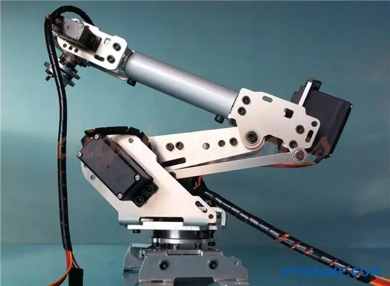
Czy kiedykolwiek zastanawiałeś się, jak mały silnik porusza ciężkim ramieniem robota? Sekret tkwi w fundamentalnym kompromisie. Podstawowa zasada działania przekładni redukcyjnych jest prosta.
Zamieniają one wysoką prędkość na wysoki moment obrotowy. O przekładni można myśleć jak o stale obracającej się dźwigni.
To działanie zwielokrotnia siłę, ale kosztem prędkości obrotowej. Ta równowaga jest kluczowa. Pozwala nam skutecznie kontrolować i wykorzystywać moc w układach mechanicznych.
| Wejście | Wyjście |
|---|---|
| Wysoka prędkość | Niska prędkość |
| Niski moment obrotowy | Wysoki moment obrotowy |
W PTSMAKE zasada ta przyświeca każdej przekładni, którą projektujemy i produkujemy.
Fizyka stojąca za kompromisem
Ta wymiana prędkości na moment obrotowy nie jest magią. Jest ona regulowana przez prawo zachowania energii. W idealnym układzie moc, którą wkładasz, jest mocą, którą otrzymujesz.
Moc jest iloczynem prędkości obrotowej i momentu obrotowego. Jeśli więc zmniejszysz prędkość, moment obrotowy musi wzrosnąć, aby utrzymać ten sam poziom mocy.
Oczywiście żaden system mechaniczny nie jest idealny. Energia zawsze jest tracona na tarcie i ciepło. To właśnie tutaj czynniki takie jak wydajność siatki1 staje się krytyczny. Określa ilościowo, ile mocy jest faktycznie przesyłane.
Jak przekładnie sprawiają, że to się dzieje
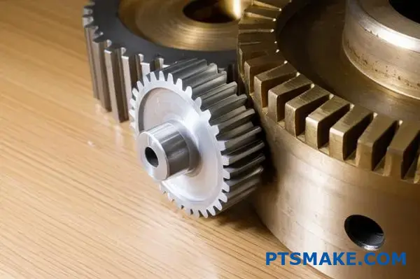
Przełożenie przekładni umożliwia ten kompromis. Jest ono określane przez liczbę zębów na przekładni wejściowej w porównaniu do przekładni wyjściowej.
Większa przekładnia wyjściowa z większą liczbą zębów obraca się znacznie wolniej niż mniejsza przekładnia wejściowa. W zamian dostarcza proporcjonalnie większy moment obrotowy. Ta mechaniczna przewaga jest źródłem jego mocy.
W naszej pracy w PTSMAKE często wykonujemy niestandardowe przekładnie. Precyzyjnie obliczamy przełożenie, aby spełnić dokładne wymagania dotyczące momentu obrotowego i prędkości dla wszystkiego, od urządzeń medycznych po robotykę.
| Zęby przekładni wejściowej | Zęby przekładni wyjściowej | Redukcja prędkości | Mnożenie momentu obrotowego |
|---|---|---|---|
| 10 | 50 | 5x | ~5x |
| 15 | 90 | 6x | ~6x |
Ta prosta zasada jest podstawą wszystkich złożonych przekładni redukcyjnych.
Podstawową zasadą działania przekładni redukcyjnych jest zamiana prędkości obrotowej na zwiększony moment obrotowy. Ta wymiana, regulowana przez oszczędność energii i przełożenia, pozwala silnikom o dużej prędkości wytwarzać potężną, kontrolowaną siłę do precyzyjnych zastosowań.
Jak zasadniczo obliczane jest przełożenie i co ono reprezentuje?
Obliczanie przełożenia jest prostsze niż się wydaje. Zasadniczo jest to porównanie przekładni napędzanej i napędzającej. Przełożenie to dyktuje ostateczną wydajność maszyny.
Najłatwiejsza metoda: Liczenie zębów
Najpopularniejszym sposobem jest liczenie zębów. Jeśli koło napędzające ma 10 zębów, a napędzane 40, przełożenie wynosi 4:1.
Alternatywne metody obliczeń
Można również użyć średnic lub prędkości kół zębatych. Zasada pozostaje ta sama - porównanie wyjścia z wejściem. Wyniki są zawsze spójne.
| Metoda obliczania | Formuła (koło zębate napędzane / koło zębate napędzające) | Przykład (napęd 40-zębowy, sterownik 10-zębowy) |
|---|---|---|
| Liczba zębów | Teeth_Driven / Teeth_Driver | 40 / 10 = 4 |
| Średnica | Diameter_Driven / Diameter_Driver | 80 mm / 20 mm = 4 |
| Prędkość kątowa | Speed_Driver / Speed_Driven | 100 OBR/MIN / 25 OBR/MIN = 4 |
Ta liczba ma kluczowe znaczenie. Informuje ona dokładnie, w jaki sposób modyfikowane są prędkość i moment obrotowy.
Przełożenie to nie tylko abstrakcyjna liczba. Reprezentuje ono fundamentalny kompromis w systemach mechanicznych: prędkość kontra moment obrotowy. Zrozumienie tego jest kluczem do efektywnego projektowania.
Podstawowa funkcja: Kompromis prędkości i momentu obrotowego
Przełożenie przekładni bezpośrednio zwielokrotnia moment obrotowy. Jednocześnie dzieli prędkość przez ten sam współczynnik. Jest to prawo fizyki; nie można otrzymać czegoś za nic. Wymieniasz prędkość na moc.
Przykładowo, przełożenie 4:1 oznacza, że wyjściowy moment obrotowy jest cztery razy większy niż wejściowy. Jednak prędkość wyjściowa będzie wynosić tylko jedną czwartą prędkości wejściowej. Zasada ta jest podstawą wszystkich przekładnie redukcyjne systemy.
Co to oznacza w praktyce
W naszych projektach w PTSMAKE stale to stosujemy. Jeśli silnik jest szybki, ale słaby, używamy wysokiego przełożenia. Taka konfiguracja zwiększa moment obrotowy w celu wykonania ciężkiej pracy. Przełożenie Przewaga mechaniczna2 Zysk pozwala małemu silnikowi poruszać dużym ramieniem robota.
Zależność ta jest odwrotna i przewidywalna. Wiedza na ten temat pozwala inżynierom wybrać idealną kombinację silnika i przekładni do każdego zadania, zapewniając wydajność i niezawodność.
| Przełożenie | Wpływ na prędkość wyjściową | Wpływ na wyjściowy moment obrotowy | Typowy przypadek użycia |
|---|---|---|---|
| 1:1 | Bez zmian | Bez zmian | Napęd bezpośredni |
| 2:1 | Zmniejszona o połowę (÷2) | Podwojony (x2) | Umiarkowany wzrost momentu obrotowego |
| 4:1 | Ćwiartowany (÷4) | Poczwórnie (x4) | Wysoki moment obrotowy, niska prędkość |
| 1:2 | Podwojony (x2) | Zmniejszona o połowę (÷2) | Zwiększenie prędkości (np. wentylatory) |
Przełożenie przekładni to proste porównanie przekładni wyjściowej i wejściowej. Ta pojedyncza liczba zasadniczo definiuje kompromis między prędkością wyjściową a wyjściowym momentem obrotowym, co jest podstawą jego praktycznej funkcji w każdym systemie mechanicznym.
Co określa wydajność systemu przekładni redukcyjnej?
Sprawność jest zasadniczo stosunkiem. Porównuje uzyskaną moc do mocy włożonej. Żaden system nie jest 100% wydajny. Energia jest zawsze tracona, często jako niepożądane ciepło.
Zrozumienie tych strat ma kluczowe znaczenie dla każdej konstrukcji mechanicznej, zwłaszcza w przypadku przekładni redukcyjnych. Przeanalizujmy, gdzie zazwyczaj ucieka ta moc.
Kluczowe obszary strat energii
| Źródło strat | Opis |
|---|---|
| Gear Mesh | Tarcie między zębami przekładni. |
| Smarowanie | Energia wykorzystywana do przetwarzania oleju lub smaru. |
| Łożyska | Tarcie w łożyskach podporowych. |
Przyjrzyjmy się bliżej tym stratom energii. Tarcie jest głównym winowajcą, występującym w wielu formach. Każda z nich wpływa na ogólną wydajność systemu, wpływając na wydajność w subtelny, ale znaczący sposób.
Straty tarcia w szczegółach
Współdziałanie zębów przekładni
Kiedy zęby przekładni zazębiają się, ślizgają się i toczą względem siebie. Powoduje to tarcie. Wykończenie powierzchni, materiał i kąt nacisku zębów odgrywają tutaj znaczącą rolę. Słaba produkcja prowadzi do bardziej szorstkich powierzchni i większych strat.
Dynamika środków smarnych
Smar jest niezbędny, ale powoduje również opór. Gdy koła zębate obracają się, obracają olej, tworząc tarcie wewnętrzne. Ten proces, obejmujący ścinanie lepkie3, Jest to szczególnie zauważalne przy dużych prędkościach lub w przypadku smarów o wysokiej lepkości.
Konsekwencje w świecie rzeczywistym
Te pozornie niewielkie straty mają poważne konsekwencje. Bezpośrednio zwiększają zużycie energii, prowadząc do wyższych kosztów operacyjnych. Stracona energia generuje również ciepło. Ciepłem tym należy zarządzać, aby zapobiec przegrzaniu, które może uszkodzić komponenty i skrócić żywotność smaru.
W poprzednich projektach w PTSMAKE pomagaliśmy klientom, koncentrując się na wąskich tolerancjach i doskonałych wykończeniach powierzchni, które bezpośrednio minimalizują te straty tarcia.
| Współczynnik strat | Główny wpływ | Wpływ wtórny |
|---|---|---|
| Tarcie zębów | Wytwarzanie ciepła | Zużycie komponentów |
| Strata na ubijaniu | Zwiększone zapotrzebowanie na moment obrotowy | Degradacja smaru |
| Tarcie łożyska | Zużycie energii | Skrócona żywotność łożyska |
Podsumowując, sprawność przekładni redukcyjnej to stosunek mocy wyjściowej do mocy wejściowej. Podstawowe straty wynikają z tarcia na zębach przekładni, w łożyskach i z ubijania smaru. Czynniki te mają bezpośredni wpływ na zużycie energii i zarządzanie temperaturą.
W jaki sposób skrzynia biegów przenosi i zwielokrotnia moment obrotowy?
Koła zębate przenoszą siłę poprzez zazębiające się zęby. O każdym kole zębatym można myśleć jak o obracającej się dźwigni. Punkt styku jest miejscem przyłożenia siły.
Zasada ramienia dźwigni
Odległość od środka koła zębatego do tego punktu styku to ramię dźwigni. Nazywamy to również promieniem skoku.
Większe koło zębate ma oczywiście dłuższe ramię dźwigni. Gdy mała przekładnia wejściowa obraca dużą przekładnię wyjściową, siła jest zwielokrotniona. Na tym polega tajemnica zwielokrotniania momentu obrotowego w przekładnie redukcyjne.
| Atrybut sprzętu | Przekładnia wejściowa (mała) | Przekładnia wyjściowa (duża) |
|---|---|---|
| Promień (ramię dźwigni) | Krótszy | Dłuższy |
| Wynikowy moment obrotowy | Niższy | Wyższy |
Ta prosta zasada ma fundamentalne znaczenie dla działania skrzyń biegów. Chodzi o dźwignię.
Fizyka mnożenia momentu obrotowego
W punkcie, w którym zęby się stykają, siła działająca na koło zębate wejściowe jest równa i przeciwna sile działającej na koło zębate wyjściowe. Jest to podstawowa zasada fizyki.
Kluczową różnicą jest odległość od środka obrotu. Nazywamy to Promień skoku4. Działa jak ramię dźwigni w systemie.
Obliczanie przewagi
Moment obrotowy to po prostu siła pomnożona przez promień (T = F × r). Ponieważ siła (F) jest taka sama dla obu zazębiających się kół zębatych, moment obrotowy jest bezpośrednio związany z promieniem. Koło zębate o dwukrotnie większym promieniu wytworzy dwukrotnie większy moment obrotowy.
Ta mechaniczna przewaga jest podstawą tego, jak przekładnie redukcyjne funkcja.
W naszych projektach w PTSMAKE precyzja jest wszystkim. Profil zęba i wybór materiału mają kluczowe znaczenie. Zapewniają one płynne przenoszenie siły. Każda niedoskonałość może prowadzić do utraty energii lub awarii komponentu, podważając całą przewagę mechaniczną.
Oto prosty przykład proporcji.
| Komponent | Promień | Siła | Moment obrotowy |
|---|---|---|---|
| Przekładnia wejściowa | 1 jednostka | 1 jednostka | 1 jednostka |
| Przekładnia wyjściowa | 3 jednostki | 1 jednostka | 3 jednostki |
To pokazuje, jak przełożenie 3:1 trzykrotnie zwiększa wyjściowy moment obrotowy. Kompromis polega na tym, że prędkość wyjściowa jest zmniejszona o ten sam współczynnik.
Zasadniczo zęby przekładni przenoszą stałą siłę. Większy promień przekładni wyjściowej działa jak dłuższe ramię dźwigni. Mechanizm ten bezpośrednio zwielokrotnia siłę wejściową, co skutkuje wyższym wyjściowym momentem obrotowym, choć przy zmniejszonej prędkości.
Jakie są kluczowe wskaźniki wydajności przekładni redukcyjnej?
Przeglądając arkusz danych przekładni redukcyjnych, łatwo pogubić się w liczbach. Jednak kilka kluczowych wskaźników naprawdę definiuje wydajność. Te specyfikacje mówią dokładnie, co może zrobić przekładnia.
Zrozumienie podstawowych liczb
Skupiamy się na tych specyfikacjach, aby dopasować odpowiedni komponent do aplikacji. Zapewnia to niezawodność i precyzję.
Moment obrotowy i prędkość
Znamionowy moment obrotowy to limit pracy ciągłej. Szczytowy moment obrotowy jest przeznaczony do krótkich serii, takich jak rozruch. Prędkość wejściowa określa maksymalne operacyjne obroty skrzyni biegów.
| Metryczny | Punkt widzenia praktyka |
|---|---|
| Znamionowy moment obrotowy | Bezpieczne, codzienne obciążenie robocze. |
| Szczytowy moment obrotowy | Limit "push it" na krótkie chwile. |
| Prędkość wejściowa | Czerwona linia, której nie należy przekraczać. |
| Przełożenie | Podstawowy kompromis między prędkością a momentem obrotowym. |
Liczby te stanowią podstawę procesu selekcji.
Niuanse: Luz i wydajność
Poza podstawowymi specyfikacjami, luz i wydajność mają kluczowe znaczenie dla systemów precyzyjnych. Często oddzielają one dobry projekt od świetnego. Czynniki te decydują o dokładności i zużyciu energii przez maszynę.
Luz to niewielka szczelina lub "luz" między zębami przekładni. W robotyce lub obróbce CNC wysoki luz może powodować niedokładności. Bezpośrednio przyczynia się do błąd pozycji5 w końcowym produkcie. Zminimalizowanie tego jest kluczowym celem w produkcji o wysokiej precyzji, wyzwaniem, któremu często stawiamy czoła w PTSMAKE.
Sprawność mierzy, ile mocy dociera od wejścia do wyjścia. Reszta jest tracona, głównie w postaci ciepła. Wyższa sprawność oznacza mniej zmarnowanej energii i prostsze zarządzanie ciepłem w systemie.
Szybkie porównanie
Różne typy przekładni oferują różne kompromisy. Wybór zależy wyłącznie od potrzeb aplikacji w zakresie precyzji i kosztów.
| Typ przekładni | Typowy luz (arc-min) | Typowa wydajność (%) |
|---|---|---|
| Ostroga | 5 - 20 | 94 - 98 |
| Planetarny | 1 - 8 | 95 - 98 |
| Harmoniczny | < 1 | 70 - 85 |
Jak widać, napęd harmoniczny oferuje niesamowitą precyzję. Odbywa się to jednak kosztem niższej wydajności w porównaniu do przekładni planetarnej.
Arkusz danych zawiera podstawowe wskaźniki dotyczące wyboru przekładni redukcyjnych. Podczas gdy moment obrotowy i przełożenie mają fundamentalne znaczenie, luz i wydajność są krytyczne dla precyzji i zużycia energii, dyktując rzeczywistą wydajność systemu i długoterminowe koszty operacyjne.
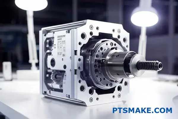
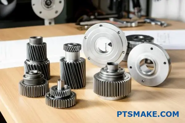
Jakie są podstawowe elementy każdej przekładni redukcyjnej?
Każda przekładnia redukcyjna, od prostej do złożonej, zbudowana jest z tych samych podstawowych części. Zrozumienie tych komponentów jest kluczem do zrozumienia ich działania. Pomyśl o tym jak o zespole, w którym każdy członek ma określone zadanie.
Niezbędni członkowie zespołu
Podstawowe komponenty płynnie ze sobą współpracują. Przenoszą moc, zmniejszają prędkość i zwielokrotniają moment obrotowy. To precyzyjny mechaniczny taniec.
Oto krótkie zestawienie głównych graczy:
| Komponent | Podstawowa funkcja |
|---|---|
| Wały (wejście/wyjście) | Przekazywanie mocy do i ze skrzyni biegów |
| Przekładnie | Serce redukcji prędkości i zwielokrotniania momentu obrotowego |
| Łożyska | Wspieranie obracających się wałów i przenoszenie obciążeń |
| Obudowa | Zapewnia ochronę i wyrównanie strukturalne |
Każda część ma kluczowe znaczenie dla niezawodnego działania przekładni redukcyjnych.
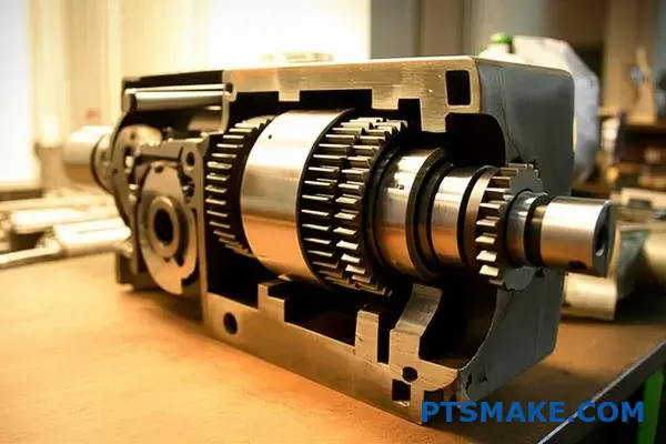
Jak komponenty współpracują ze sobą
Skrzynia biegów to coś więcej niż suma jej części. To zrównoważony system. Obudowa, na przykład, nie jest tylko obudową ochronną. Jej sztywność i precyzja są niezbędne do utrzymania idealnego ustawienia kół zębatych i łożysk.
Ścieżka przepływu mocy
Moc wchodzi przez wał wejściowy. Napędza on pierwszy bieg w układzie. Gdy biegi zazębiają się, prędkość spada, a moment obrotowy rośnie. Ta zmodyfikowana moc wychodzi następnie przez wał wyjściowy. Jest to bezpośredni i wydajny transfer energii.
Wsparcie systemu
Proces ten generuje znaczne siły. Łożyska odgrywają kluczową rolę we wspieraniu wałów przed tymi obciążeniami promieniowymi i osiowymi. Bez odpowiednich łożysk tarcie szybko doprowadziłoby do katastrofalnej awarii. Uszczelki są niedocenianymi bohaterami, utrzymując niezbędny smar wewnątrz i szkodliwe zanieczyszczenia na zewnątrz. Odpowiedni smar minimalizuje zużycie pomiędzy ruchomymi częściami, zarządzając ciepłem i zapobiegając przedwczesnym awariom spowodowanym czynnikami takimi jak Naprężenie kontaktowe Hertza6.
W naszej pracy w PTSMAKE często widzimy awarie wynikające z jednego niedocenianego komponentu.
| Komponent | Krytyczna rola w integralności systemu |
|---|---|
| Obudowa | Utrzymuje precyzyjne wyrównanie wszystkich części wewnętrznych |
| Smar | Zmniejsza tarcie, rozprasza ciepło i czyści komponenty |
| Uszczelki | Ochrona systemu przed zanieczyszczeniami zewnętrznymi i utratą środka smarnego |
Awaria któregokolwiek z tych komponentów może zagrozić całej skrzyni biegów.
Każdy komponent jest krytycznym ogniwem. Obudowa zapewnia wyrównanie, koła zębate przenoszą moc, łożyska zarządzają obciążeniami, a uszczelki chronią elementy wewnętrzne. Awaria jednej części nieuchronnie spowoduje kaskadę, wpływając na wydajność i żywotność całego systemu.
Jakie są główne klasyfikacje przekładni redukcyjnych?
Jednym z najbardziej przejrzystych sposobów klasyfikacji przekładni redukcyjnych jest orientacja ich wałów. Ta fundamentalna różnica dyktuje sposób przenoszenia ruchu i momentu obrotowego. Jest to pierwsza rzecz, którą bierzemy pod uwagę.
Zrozumienie tego pomaga wybrać odpowiedni projekt. Ma to wpływ na wydajność, przestrzeń i koszty.
Przekładnie z osią równoległą
W tym przypadku wały wejściowy i wyjściowy są równoległe. Jest to najczęściej spotykany układ.
- Przekładnie zębate czołowe: Proste, proste zęby.
- Przekładnie śrubowe: Zęby ustawione pod kątem zapewniają płynniejszą pracę.
Przekładnie z przecinającymi się osiami
Te koła zębate mają wały, które przecinają się, zwykle pod kątem 90 stopni.
- Przekładnie kątowe: Przekładnie w kształcie stożka do zmiany kierunku obrotów.
Nieprzecinająca się, nierównoległa oś
Wały w tej grupie krzyżują się w różnych płaszczyznach i nie przecinają się.
| Orientacja wału | Typowe rodzaje przekładni |
|---|---|
| Równoległy | Ostroga, spirala |
| Przecinające się | Skos |
| Nieingerujący | Ślimak, hipoidalny |
Przyjrzyjmy się bliżej tym klasyfikacjom. Wybór typu przekładni ma kluczowe znaczenie dla wydajności. Jest to kluczowy punkt dyskusji w naszych projektach w PTSMAKE. Pomagamy klientom zrównoważyć wydajność z ograniczeniami projektowymi.
Oś równoległa: konie robocze
Przekładnie czołowe są opłacalne i łatwe w produkcji. Świetnie nadają się do wielu zastosowań, ale mogą być głośne przy dużych prędkościach.
Przekładnie śrubowe działają płynniej i ciszej. Ich skośne zęby zazębiają się stopniowo. Jednak taka konstrukcja tworzy nacisk osiowy7, co wymaga specjalnego podparcia łożyska. Jest to kluczowy szczegół często pomijany na wczesnych etapach projektowania.
Kątowe przenoszenie mocy
Przekładnie kątowe są niezbędne do przenoszenia mocy pod kątem prostym. Są one powszechne we wszystkim, od wiertarek ręcznych po samochodowe mechanizmy różnicowe. Ich stożkowy kształt umożliwia przecinanie się wałów i zmianę kierunku obrotu.
Wysokie współczynniki redukcji
Przekładnie ślimakowe doskonale nadają się do osiągania wysokich przełożeń redukcyjnych na niewielkiej przestrzeni. Ślimak napędza koło ślimakowe. Taka konfiguracja jest naturalnie samoblokująca. Zapobiega to jeździe wstecz, co jest przydatne ze względów bezpieczeństwa.
Wreszcie, bierzemy również pod uwagę, czy przekładnia jest otwarta czy zamknięta. Systemy zamknięte chronią przekładnie przed zanieczyszczeniami i zawierają smar, wydłużając ich żywotność. Otwarte przekładnie są prostsze, ale wymagają większej konserwacji.
| Typ przekładni | Kluczowa zaleta | Wspólna aplikacja |
|---|---|---|
| Ostroga | Opłacalność | Systemy przenośników |
| Spirala | Płynna i cicha praca | Samochodowe skrzynie biegów |
| Skos | Zmienia kąt obrotu | Wiertarki ręczne |
| Robak | Wysoki współczynnik redukcji | Windy, podnośniki |
Klasyfikacja przekładni redukcyjnych według orientacji wału - równoległej, przecinającej się lub nieprzecinającej się - zapewnia jasne ramy. Każdy typ oferuje określone korzyści dla różnych zastosowań. Wybór między systemem otwartym lub zamkniętym dodatkowo określa trwałość przekładni i potrzeby konserwacyjne.
Jak systematycznie wybierać przekładnię redukcyjną do danego zastosowania?
Wybór odpowiedniej przekładni redukcyjnej nie polega na zgadywaniu. Wymaga to jasnego procesu krok po kroku. Metoda ta zapewnia wydajność i niezawodność, których potrzebujesz.
Wszystko zaczyna się od zrozumienia podstawowych wymagań aplikacji. Bez tej podstawy wybór będzie od samego początku obarczony błędem.
Krok 1: Określenie wymagań aplikacji
Najpierw musimy zdefiniować parametry operacyjne. Liczby te są podstawą całego procesu selekcji.
Oto kluczowe wskaźniki do ustalenia:
| Parametr | Jednostka | Opis |
|---|---|---|
| Prędkość wejścia/wyjścia | RPM | Wymagana prędkość obrotowa dla obciążenia. |
| Wymagany moment obrotowy | Nm | Siła obrotowa potrzebna do napędzania ładunku. |
| Cykl pracy | % lub godziny/dzień | Jak często i jak długo sprzęt będzie działał. |
Krok 2: Obliczenie obciążenia i zastosowanie współczynnika serwisowego
Po określeniu podstawowych wymagań należy obliczyć rzeczywiste obciążenie operacyjne. Wiąże się to z krytycznym elementem: współczynnikiem obsługi.
Współczynnik serwisowy jest mnożnikiem. Uwzględnia on rzeczywiste warunki, takie jak obciążenia udarowe i zmiany temperatury. Zapewnia niezbędny margines bezpieczeństwa.
Niedopasowanie bezwładności systemu może prowadzić do niskiej wydajności. Prawidłowe obliczenia zapobiegają temu. Obliczenia niedopasowanie bezwładności8 między silnikiem a obciążeniem jest kluczowym czynnikiem. W PTSMAKE pomagamy klientom poruszać się po tych złożonych obliczeniach.
Krok 3: Wybierz typ sprzętu
Wybór zależy w dużej mierze od ograniczeń projektu. Przestrzeń, wymagana precyzja i budżet pomogą wybrać odpowiedni typ przekładni redukcyjnej.
Rozważ te typowe kompromisy:
| Typ przekładni | Kluczowa zaleta | Wspólne ograniczenie |
|---|---|---|
| Ostroga | Opłacalność, prostota | Hałaśliwy, niższy moment obrotowy |
| Spirala | Cicha i płynna praca | Wyższy koszt, nacisk osiowy |
| Planetarny | Wysoki moment obrotowy, kompaktowa konstrukcja | Złożoność, wyższe koszty |
| Robak | Wysoki stopień redukcji, samoblokujący | Niższa wydajność |
Krok 4: Zapoznanie się z katalogiem
Po określeniu wszystkich specyfikacji można teraz zapoznać się z katalogiem producenta. Dopasuj obliczony moment obrotowy, prędkość i współczynnik serwisowy do konkretnego modelu. Ten ostatni krok potwierdza dokonany wybór.
Ten systematyczny, czteroetapowy proces - definiowanie potrzeb, obliczanie obciążenia, wybór typu przekładni i sprawdzanie katalogu - eliminuje niepewność. Gwarantuje to, że wybrana przekładnia redukcyjna idealnie pasuje do wymagań aplikacji, zapewniając optymalną wydajność i trwałość.
Jakie są najważniejsze etapy doboru rozmiaru skrzyni biegów?
Praktyczny przepływ obliczeń jest kluczowy. Przekształca on złożone wymagania w jasną specyfikację. Proces ten zapewnia, że przekładnia nie jest tylko dopasowaniem, ale trwałym rozwiązaniem.
Zacznij od wymagań podstawowych
Najpierw należy zdefiniować wymagany wyjściowy moment obrotowy i prędkość. Są to niepodlegające negocjacjom wartości docelowe wydajności maszyny. Stanowią one podstawę wszystkich kolejnych obliczeń.
Czynnik w stresie aplikacji
Następnie należy wziąć pod uwagę rzeczywiste warunki pracy. Obejmuje to obciążenia udarowe i ogólny cykl pracy. Czynniki te mają znaczący wpływ na zużycie.
Prosty sposób klasyfikacji obciążeń:
| Typ obciążenia | Opis | Przykład |
|---|---|---|
| Mundur | Płynna, ciągła praca | Przenośnik taśmowy |
| Umiarkowany wstrząs | Rutynowe uruchamianie i zatrzymywanie | Tabela indeksowania |
| Silny wstrząs | Gwałtowne, silne uderzenia | Kruszarka do skał |
Krytyczna rola czynnika usługowego (SF)
Współczynnik serwisowy (SF) jest mnożnikiem. Dostosowuje on wymagany bazowy moment obrotowy w celu uwzględnienia trudnych warunków zastosowania. Uwzględnia on takie czynniki jak Cykl pracy9 i typ obciążenia.
Ignorowanie SF to powszechna droga na skróty, która często prowadzi do przedwczesnej awarii. Jest to margines bezpieczeństwa, który zapewnia niezawodność w długim okresie.
Wyższy współczynnik SF jest wymagany w przypadku bardziej wymagających zadań. Współpracując z naszymi klientami, odkryliśmy, że dobrze dobrany SF ma kluczowe znaczenie dla długowieczności niestandardowych przekładni redukcyjnych.
Obliczanie nominalnego momentu obrotowego
Formuła jest prosta:
Wymagany nominalny moment obrotowy = wyjściowy moment obrotowy aplikacji × współczynnik serwisowy
To obliczenie daje minimalny ciągły moment obrotowy, którego należy szukać w katalogu producenta.
Oto uproszczony przykład sposobu określania SF:
| Godziny pracy / dzień | Jednolite obciążenie | Umiarkowany wstrząs | Silny wstrząs |
|---|---|---|---|
| Do 2 | 1.00 | 1.25 | 1.75 |
| 3-10 | 1.25 | 1.50 | 2.00 |
| Ponad 10 | 1.50 | 1.75 | 2.25 |
Weryfikacja zgodności ze specyfikacjami
Na koniec należy obliczyć nominalny moment obrotowy. Porównaj go ze specyfikacjami dostarczonymi przez producenta przekładni. Nominalny moment obrotowy podany w katalogu musi być równy lub większy od obliczonej wartości. W PTSMAKE zawsze dwukrotnie sprawdzamy te szczegóły, aby zapobiec kosztownym błędom.
Ten systematyczny przepływ pracy przekształca potrzeby aplikacji w konkretną specyfikację przekładni. Zaczynając od momentu obrotowego i prędkości, stosując współczynnik serwisowy i weryfikując z arkuszami danych, zapewniasz niezawodny i trwały wybór. Zapobiega to niedowymiarowaniu i wydłuża żywotność komponentów.
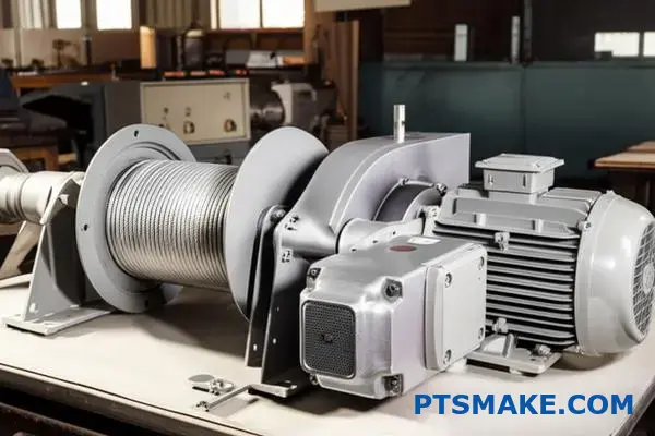
Jak obliczyć wymagany moment obrotowy do podnoszenia?
Przyjrzyjmy się praktycznemu przykładowi. Teoria jest świetna, ale zobaczenie liczb sprawia, że wszystko staje się jasne. Obliczymy moment obrotowy wymagany dla prostego systemu wciągarki.
Obliczenie to jest proste. Obejmuje ono ciężar ładunku, promień bębna i tarcie systemowe. Omówimy to krok po kroku.
Oto zmienne, których będziemy używać:
| Zmienna | Opis |
|---|---|
| Masa ładunku | Ciężar, który musimy podnieść. |
| Promień bębna | Promień bębna wciągarki. |
| Wydajność systemu | Uwzględnia tarcie i straty. |
Proces ten pomaga wybrać odpowiedni silnik i przekładnię.
Przykład obliczeń krok po kroku
Wyobraźmy sobie typowy scenariusz. Musimy zaprojektować wciągarkę do podnoszenia ładunku o masie 100 kg. Jest to typowa waga dla wielu zastosowań przemysłowych, które obsługujemy w PTSMAKE.
Krok 1: Określenie siły
Najpierw przekształć masę w siłę liniową. Używamy przyspieszenia grawitacyjnego (około 9,8 m/s²).
- Siła (F) = Masa (m) × Grawitacja (g)
- Siła (F) = 100 kg × 9,8 m/s² = 980 niutonów (N)
Jest to siła ciągnąca kabel w dół.
Krok 2: Obliczenie idealnego momentu obrotowego
Załóżmy teraz, że bęben naszej wciągarki ma promień 0,1 metra (100 mm). Idealny moment obrotowy to siła pomnożona przez promień.
- Moment obrotowy (T) = Siła (F) × Promień (r)
- Moment obrotowy (T) = 980 N × 0,1 m = 98 niutonometrów (Nm)
Jest to wymagany moment obrotowy bez uwzględnienia jakichkolwiek nieefektywności.
Krok 3: Uwzględnienie rzeczywistych strat
Żaden system mechaniczny nie jest doskonały. Musimy wziąć pod uwagę Straty tarcia10 w łożyskach, przekładniach i innych komponentach. Konserwatywny szacunek wydajności to 80% (lub 0,8).
Aby znaleźć rzeczywisty wymagany moment obrotowy, dzielimy idealny moment obrotowy przez współczynnik sprawności.
- Wymagany moment obrotowy = idealny moment obrotowy / wydajność
- Wymagany moment obrotowy = 98 Nm / 0,8 = 122,5 Nm
Ta wartość 122,5 Nm jest potrzebna do wyboru odpowiedniego silnika i przekładni redukcyjnej. Przekładnia redukcyjna zwielokrotnia moment obrotowy silnika, aby spełnić ten wymóg.
W tym przykładzie idealny moment obrotowy wynosił 98 Nm. Jednak po uwzględnieniu tarcia w układzie wymagany moment obrotowy wzrósł do 122,5 Nm. Ten margines bezpieczeństwa ma kluczowe znaczenie dla niezawodnego działania i zapobiegania awariom podzespołów.
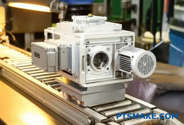
Wybór przekładni dla systemu przenośnika taśmowego o stałej prędkości.
Przyjrzyjmy się praktycznemu studium przypadku. Klient potrzebował przekładni do systemu transportującego pakowane towary. Głównym celem była niezawodność, a nie dokładność.
System przenośników miał specyficzne wymagania operacyjne. Oto podstawowe parametry, od których zaczęliśmy:
| Parametr | Wartość |
|---|---|
| Napięcie paska | 500 N |
| Średnica koła pasowego | 0,2 metra |
| Pożądana prędkość taśmy | 1,5 m/s |
| Cykl pracy | 16 godzin/dzień |
Naszym zadaniem było wybranie trwałego i opłacalnego rozwiązania. Skupiliśmy się wyłącznie na spójnym, długoterminowym działaniu.
Obliczanie podstawowego zapotrzebowania: Moment obrotowy
Najpierw musimy określić wymagany wyjściowy moment obrotowy. Jest to proste obliczenie. Gwarantuje ono, że skrzynia biegów poradzi sobie z obciążeniem bez zgaśnięcia lub awarii.
Formuła momentu obrotowego
Wzór jest prosty: Moment obrotowy (τ) jest równy napięciu paska (F) pomnożonemu przez promień koła pasowego (r).
τ = F × r
Korzystając z naszych numerów studium przypadku:
- Siła (F) = 500 N
- Promień (r) = 0,2 m / 2 = 0,1 m
- Moment obrotowy (τ) = 500 N × 0,1 m = 50 Nm
Te 50 Nm to nasz minimalny wymagany moment obrotowy. Bierzemy również pod uwagę Współczynnik usługi11 aby uwzględnić długi cykl pracy. Zapewnia to trwałość.
Uzasadnienie wyboru skrzyni biegów
W tym zastosowaniu wysoka precyzja jest zbędna. To natychmiast wyklucza droższe opcje, takie jak precyzyjne przekładnie planetarne. Potrzebujemy solidnych, niezawodnych przekładni redukcyjnych.
Najlepszym wyborem są przekładnie walcowe lub ślimakowe. Obie oferują doskonałą niezawodność w zastosowaniach wymagających stałej prędkości.
| Typ skrzyni biegów | Kluczowa zaleta | Najlepsze dla |
|---|---|---|
| Spirala | Wysoka wydajność (90-98%) | Energooszczędne systemy |
| Robak | Samoblokujący, cichy | Aplikacje o krytycznym znaczeniu dla bezpieczeństwa |
Biorąc pod uwagę potrzebę opłacalności i niezawodności, przekładnia walcowa była idealnym rozwiązaniem. Jej wydajność zapewnia również długoterminowe oszczędności kosztów operacyjnych. Przekładnia ślimakowa jest również silnym konkurentem.
W tym studium przypadku obliczyliśmy wymagany moment obrotowy 50 Nm dla przenośnika. W oparciu o potrzebę niezawodności ponad precyzję, ekonomiczna przekładnia walcowa lub ślimakowa była oczywistym i uzasadnionym wyborem dla długoterminowej wydajności.
Wybór przekładni dla określonego przegubu ramienia robota.
Przeanalizujmy precyzyjny przegub robota. Pomyślmy o robocie składającym smartfona. Każdy ruch musi być perfekcyjny. Taki poziom dokładności wymaga od przekładni określonych cech.
Wymagania krytyczne
Wysoka sztywność jest niezbędna, aby wytrzymać ugięcie pod obciążeniem. Potrzebujemy również minimalnego luzu, aby wyeliminować luz. Niska bezwładność pozwala na szybkie przyspieszanie i zatrzymywanie. Wybór przekładni redukcyjnej ma tutaj kluczowe znaczenie.
Potrzeby aplikacji w skrócie
| Cecha | Precyzyjny przegub | Standardowa aplikacja |
|---|---|---|
| Dokładność | Poniżej milimetra | Niski |
| Prędkość | Bardzo wysoka | Umiarkowany |
| Powtarzalność | Kluczowe | Nie krytyczny |
| Backlash | Blisko zera | Tolerowalny |
Zanurzenie się w przekładniach o wysokiej precyzji
W przypadku bardzo precyzyjnych zadań każdy szczegół ma znaczenie. Wysoka sztywność sprawia, że ramię nie wygina się ani nie wibruje podczas ruchu lub przenoszenia obciążenia. Ma to bezpośredni wpływ na końcową dokładność pozycjonowania.
Niska bezwładność jest kolejnym kluczowym czynnikiem. Lżejszy system o niskiej bezwładności pozwala silnikowi znacznie szybciej przyspieszać i zwalniać złącze. Skraca to czas cyklu w operacjach pick-and-place, zwiększając produktywność.
Gra mechaniczna lub luz12, musi wynosić prawie zero. Wszelkie luzy w przekładniach przekładają się na błędy pozycjonowania na końcu ramienia. Jest to niedopuszczalne w mikroelektronice lub montażu urządzeń medycznych. W poprzednich projektach PTSMAKE widzieliśmy, jak nawet niewielkie błędy mogą powodować poważne awarie produkcyjne.
Porównaj to z prostą przekładnią przenośnika taśmowego. Jej głównym zadaniem jest ciągły ruch. Niewielki luz lub lekkie ugięcie nie ma wpływu na jej działanie. Dlatego też odpowiednia jest standardowa, tańsza przekładnia.
Najlepsi zawodnicy pod względem precyzji
W przypadku wymagających zastosowań wyróżniają się dwa rodzaje przekładni redukcyjnych.
| Typ skrzyni biegów | Kluczowa zaleta | Najlepszy przypadek użycia |
|---|---|---|
| Napęd harmoniczny | Bez luzów, kompaktowy | Zrobotyzowane nadgarstki, precyzyjne stawy |
| Precyzyjny układ planetarny | Wysoka sztywność, wysoki moment obrotowy | Przeguby o większej ładowności, maszyny CNC |
Wybór pomiędzy nimi często zależy od momentu obrotowego i sztywności konkretnego złącza. Wyniki naszych testów pokazują, że napędy harmoniczne wyróżniają się w kompaktowych przestrzeniach wymagających najwyższej precyzji.
W przypadku robotyki o wysokiej precyzji nie można iść na kompromis. Wymagania aplikacji dotyczące wysokiej sztywności, niemal zerowego luzu i niskiej bezwładności kierują wyborem. Prowadzi to bezpośrednio do zaawansowanych rozwiązań, takich jak napędy harmoniczne lub precyzyjne przekładnie planetarne, w przeciwieństwie do prostszych, bardziej tolerancyjnych zastosowań.
Jak rozwiązać problem nadmiernego hałasu i wibracji w skrzyni biegów?
Logiczne podejście jest kluczowe. Używam drzewa diagnostycznego do systematycznego eliminowania potencjalnych przyczyn. Metoda ta oszczędza czas i zapobiega zgadywaniu. Prowadzi od prostych kontroli do bardziej złożonych inspekcji.
Zacznij od podstaw
Najpierw zbierz informacje. Kiedy zaczął się hałas? Czy ostatnio coś się zmieniło? Odpowiedzi na te pytania dostarczają cennych wskazówek. Następnie przejdź do kontroli sensorycznej.
Wyizolowanie przyczyny
Następnym krokiem jest ustalenie dokładnego źródła. Różne problemy generują różne dźwięki. Takie systematyczne podejście gwarantuje, że nie pominiesz żadnego krytycznego kroku. Chodzi o bycie metodycznym.
Oto kilka często używanych przeze mnie narzędzi:
| Narzędzie | Cel |
|---|---|
| Stetoskop | Izolacja źródeł hałasu (łożyska, przekładnie) |
| Termometr na podczerwień | Sprawdź, czy komponenty nie przegrzewają się |
| Czujniki | Sprawdź wyrównanie i luz |
Ten ustrukturyzowany proces szybko zawęża możliwości.
Aby zanurzyć się głębiej, musimy rozróżnić rodzaje dźwięków i wibracji. Metodyczny proces jest najlepszym narzędziem. W PTSMAKE stosujemy ten sam rygor podczas produkcji precyzyjnych komponentów do systemów przekładni, w tym złożonych przekładni redukcyjnych.
Słuchanie wskazówek
Doskonale nadaje się do tego stetoskop mechaniczny. Umieść sondę na różnych częściach obudowy skrzyni biegów. Zużyte łożysko często wydaje dudniący lub zgrzytający dźwięk. Uszkodzone zęby przekładni mogą powodować wycie lub klikanie, które zmienia się wraz z prędkością.
Kontrole wizualne i fizyczne
Po odsłuchaniu przeprowadź kontrolę wzrokową. Sprawdź, czy nie ma wycieków, które mogą wskazywać na uszkodzenie uszczelki lub przegrzanie. Zwróć uwagę na wszelkie oznaki zewnętrznego uszkodzenia obudowy.
Następnie należy sprawdzić ustawienie silnika i przekładni. Niewspółosiowość jest bardzo częstym źródłem wibracji. Często okazuje się, że nawet niewielki błąd w tym miejscu może powodować poważne problemy. Użycie odpowiednich narzędzi zapewnia dokładność. Zasady Analiza wibracji13 może określić te kwestie z niewiarygodną precyzją.
| Objaw | Potencjalna przyczyna | Następny krok |
|---|---|---|
| Wysoki dźwięk | Uszkodzone zęby przekładni | Kontrola kół zębatych |
| Dudnienie/zgrzytanie | Zużyte łożyska | Izolacja i kontrola łożysk |
| Konsekwentne klikanie | Złamany ząb | Natychmiastowe wyłączenie i inspekcja |
| Intensywne wibracje | Niewspółosiowość | Sprawdź i skoryguj ustawienie |
To drzewo diagnostyczne pomaga skutecznie izolować problemy. Przechodzi od ogólnych obserwacji do konkretnych testów. Zapewnia to dokładną i precyzyjną diagnozę za każdym razem.
Drzewo diagnostyczne zapewnia ustrukturyzowaną ścieżkę identyfikacji pierwotnej przyczyny hałasu i wibracji. Zaczyna się od prostych kontroli sensorycznych i przechodzi do konkretnych inspekcji opartych na narzędziach, skutecznie izolując problemy od niewspółosiowości do wewnętrznego zużycia komponentów.
Jakie są wyzwania związane ze sprzężeniem silnika z przekładnią?
Wybór odpowiedniego złącza to coś więcej niż zwykłe połączenie mechaniczne. Jest to krytyczna decyzja, która bezpośrednio wpływa na żywotność i wydajność systemu.
Sprzęgło musi uwzględniać niewielkie niewspółosiowości między silnikiem a przekładnią. Musi również pochłaniać wibracje i niezawodnie przenosić moment obrotowy.
Ignorowanie tych czynników prowadzi do przedwczesnej awarii. Może to spowodować kosztowne przestoje i naprawy. Zły wybór w tym przypadku podważa cały projekt układu napędowego. Jest to niewielka część o ogromnym wpływie.
Niewspółosiowość: Nieunikniona rzeczywistość
Żaden zespół nie jest idealnie wyrównany. Zawsze będą występować niewielkie równoległe lub kątowe niewspółosiowości. Sztywne sprzęgło nie jest w stanie sobie z tym poradzić. Przenosi ono naprężenia bezpośrednio na łożyska silnika i przekładni. Prowadzi to do szybkiego zużycia i ostatecznej awarii. Elastyczne sprzęgła są zaprojektowane tak, aby absorbować te drobne niedoskonałości. Chronią one droższe komponenty.
Tłumienie drgań i przenoszenie momentu obrotowego
Kolejnym istotnym problemem są wibracje. Silniki naturalnie wytwarzają wibracje, które mogą uszkodzić delikatne elementy przekładni, szczególnie w przypadku bardzo precyzyjnych przekładni. przekładnie redukcyjne. Dobre sprzęgło tłumi te drgania. Zapobiega to rezonansowi i wydłuża żywotność łożysk i przekładni. Zapewnia również płynniejszą i cichszą pracę. Sprzęgło Sztywność skrętna14 odgrywa tutaj kluczową rolę. Musi być wystarczająco sztywny, aby przenosić moment obrotowy bez strat, ale wystarczająco elastyczny, aby tłumić drgania.
Konsekwencje złego wyboru
W naszych projektach w PTSMAKE widzieliśmy bezpośrednie skutki złego doboru złącza. Zły wybór może być katastrofalny w skutkach. Poniższa tabela przedstawia kilka typowych problemów, które zaobserwowaliśmy u klientów.
| Problem ze sprzęgłem | Konsekwencje |
|---|---|
| Zbyt sztywny | Przedwczesna awaria łożyska |
| Niewłaściwy rozmiar | Poślizg, utrata momentu obrotowego, awaria |
| Słabe tłumienie | Zwiększony hałas i wibracje |
| Niezgodność materiałowa | Korozja, wczesna awaria |
Prawidłowy wybór od samego początku pozwala zaoszczędzić sporo czasu i pieniędzy. Jest to podstawowy krok dla niezawodnego systemu mechanicznego.
Wybór odpowiedniego sprzęgła ma kluczowe znaczenie. Chroni ono system, dostosowując się do niewspółosiowości, tłumiąc drgania i skutecznie przenosząc moment obrotowy. Zły wybór prowadzi do przedwczesnego zużycia, zwiększonego hałasu i kosztownych awarii, podważając niezawodność i wydajność całego projektu.
Kiedy należy wybrać wysokowydajną, a kiedy tańszą skrzynię biegów?
Myślenie wykraczające poza początkową cenę ma kluczowe znaczenie. Całkowity koszt posiadania (TCO) przedstawia prawdziwą historię. Obejmuje on cenę zakupu, koszty energii i konserwacji przez cały okres eksploatacji przekładni.
W przypadku aplikacji, które działają stale, jest to bardzo ważne.
Koszt początkowy a długoterminowe oszczędności
Tańsza skrzynia biegów może zaoszczędzić pieniądze dzisiaj. Ale w dłuższej perspektywie może kosztować więcej. Wysokowydajne przekładnie redukcyjne zużywają mniej energii. Pozwala to zaoszczędzić pieniądze w każdej godzinie pracy.
Rozważmy ten prosty podział:
| Współczynnik kosztów | Wysokowydajna skrzynia biegów | Tańsza skrzynia biegów |
|---|---|---|
| Cena początkowa | Wyższy | Niższy |
| Koszt energii | Niższy | Wyższy |
| Konserwacja | Często niższe | Potencjalnie wyższy |
Ta zmiana perspektywy jest kluczem do inteligentnej inżynierii i zaopatrzenia.
Analiza aplikacji do pracy ciągłej
Przejdźmy do konkretów. Praca ciągła oznacza, że maszyna pracuje 24 godziny na dobę, 7 dni w tygodniu lub na bardzo długich zmianach. W takich przypadkach zużycie energii staje się głównym kosztem operacyjnym. Wysokowydajna przekładnia, taka jak przekładnia walcowa, może być ponad 95% wydajna.
Tańsza przekładnia ślimakowa może być tylko 70-80% wydajna. Ta różnica w stratach energii szybko się sumuje.
Scenariusz TCO: przekładnia ślimakowa vs. przekładnia walcowa
Wyobraźmy sobie dwa silniki pracujące w sposób ciągły. Jeden z nich ma przekładnię śrubową, a drugi ślimakową. Początkowa inwestycja w przekładnię ślimakową jest wyższa.
Jednak po przeprowadzeniu testów z klientami zauważyliśmy, że oszczędności energii wynikające z zastosowania przekładni zębatej śrubowej zaczynają równoważyć początkowy koszt w ciągu kilku lat. Konkretny Okres zwrotu15 zależy od lokalnych cen energii i stopnia wykorzystania urządzenia.
Oto uproszczone spojrzenie na koszty w czasie:
| Ramy czasowe | Przekładnia walcowa (wysoka wydajność) | Przekładnia ślimakowa (niższy koszt) |
|---|---|---|
| Rok 1 | Wysoki koszt początkowy + niski koszt energii | Niski koszt początkowy + wysoki koszt energii |
| Rok 3 | Niższy koszt całkowity dzięki oszczędnościom | Całkowity koszt wyższy ze względu na zużycie energii |
| Rok 5 | Znaczące długoterminowe oszczędności | Stale rosnące koszty operacyjne |
W przypadku każdego systemu przeznaczonego do długotrwałej, nieprzerwanej pracy, droga wysokiej wydajności często okazuje się najbardziej ekonomicznym wyborem. W PTSMAKE prowadzimy klientów przez tę analizę, aby zapewnić im najlepszą wartość w całym cyklu życia produktu.
Gdy aplikacja działa w sposób ciągły, całkowity koszt posiadania często faworyzuje wysokowydajną przekładnię. Długoterminowe oszczędności energii mogą z łatwością przewyższyć wyższą początkową cenę zakupu, co z czasem sprawia, że jest to mądrzejszy wybór finansowy.
Jakie są nowe trendy w technologii przekładni redukcyjnych?
Przyszłość technologii przekładni redukcyjnych jest ekscytująca. Wychodzimy poza prostą mechanikę. Przekładnie stają się coraz bardziej inteligentne i wydajne każdego dnia.
Inteligentne koła zębate i IIoT
Czujniki są teraz wbudowane w układy przekładni. Pozwala to na monitorowanie stanu w czasie rzeczywistym. Pozwala to przewidywać awarie przed ich wystąpieniem, co oszczędza cenny czas produkcji.
Innowacje w zakresie materiałów i powłok
Kluczowe znaczenie mają również nowe materiały i powłoki. Zwiększają one trwałość i zmniejszają tarcie. Prowadzi to bezpośrednio do wyższej wydajności i dłuższej żywotności nowoczesnych przekładni redukcyjnych.
| Cecha | Podejście tradycyjne | Pojawiający się trend |
|---|---|---|
| Monitorowanie | Inspekcja ręczna | Czujniki czasu rzeczywistego (IIoT) |
| Materiały | Standardowe stopy stali | Zaawansowane kompozyty/powłoki |
Mechanika inteligentnych przekładni redukcyjnych
Integracja czujników to coś więcej niż tylko dodanie elektroniki. Chodzi o stworzenie pętli sprzężenia zwrotnego. Dane dotyczące temperatury, wibracji i jakości smarowania są stale gromadzone. Informacje te pomagają nam przewidywać i zapobiegać awariom.
Takie podejście, znane jako konserwacja predykcyjna, minimalizuje nieoczekiwane przestoje. W poprzednich projektach PTSMAKE widzieliśmy, że ta zmiana pozwala klientom zaoszczędzić znaczne koszty operacyjne w dłuższej perspektywie.
Przesuwanie granic za pomocą materiałów
Materiały, których używamy, zmieniają wszystko. Zaawansowane polimery i kompozyty ceramiczne oferują mniejszą wagę i lepszą odporność na zużycie w porównaniu z tradycyjnymi metalami.
Rola zaawansowanych powłok
Powłoki takie jak Diamond-Like Carbon (DLC) są niesamowite. Tworzą one powierzchnię o bardzo niskim współczynniku tarcia. Zmniejsza to straty energii i generowanie ciepła. W oparciu o nasze testy, może to poprawić wydajność o kilka punktów procentowych, co ma duże znaczenie w zastosowaniach o wysokiej wydajności.
Specjalistyczne przekładnie dla nowych granic
Robotyka i pojazdy elektryczne (EV) mają wyjątkowe wymagania. Ramiona robotów wymagają skrzyń biegów o niemal zerowym przełożeniu. luz16 dla precyzyjnych ruchów.
Pojazdy elektryczne wymagają przekładni redukcyjnych, które mogą cicho i wydajnie obsługiwać bardzo wysokie prędkości wejściowe. Wymaga to zupełnie nowych filozofii projektowania i technik produkcji, które aktywnie rozwijamy wraz z naszymi partnerami.
Przyszłość przekładni redukcyjnych zależy od inteligencji i specjalizacji. Integracja czujników do monitorowania, wykorzystanie zaawansowanych materiałów dla lepszej wydajności oraz projektowanie wyspecjalizowanych jednostek dla robotyki i pojazdów elektrycznych to kluczowe trendy kształtujące kolejny rozdział branży.
Odblokuj doskonałość przekładni redukcyjnych dzięki PTSMAKE już dziś
Przenieś swoje projekty na wyższy poziom dzięki precyzyjnym przekładniom redukcyjnym i bezbłędnej produkcji od PTSMAKE. Skontaktuj się z nami już teraz, aby uzyskać szybką, niezobowiązującą wycenę - skorzystaj ze sprawdzonej wiedzy, krótkich czasów realizacji i niezachwianej jakości przy następnym zapotrzebowaniu na obróbkę CNC lub formowanie wtryskowe!

Dowiedz się, jak konstrukcja przekładni i smarowanie wpływają na rzeczywistą moc wyjściową systemów mechanicznych. ↩
Dowiedz się, w jaki sposób ta podstawowa zasada fizyki umożliwia zwielokrotnianie siły w układach mechanicznych. ↩
Z naszego szczegółowego przewodnika dowiesz się, jak dynamika płynów wpływa na wydajność środka smarnego i ogólną wydajność przekładni. ↩
Poznaj ten kluczowy wymiar przekładni i dowiedz się, jak bezpośrednio wpływa on na obliczenia momentu obrotowego i konstrukcję przekładni. ↩
Dowiedz się, jak ta niewielka luka mechaniczna może prowadzić do znacznych niedokładności w precyzyjnych systemach sterowania ruchem. ↩
Dowiedz się więcej o tym kluczowym czynniku naprężenia, który określa trwałość powierzchni i nośność kół zębatych i łożysk. ↩
Dowiedz się, jak nacisk osiowy wpływa na wybór łożyska i ogólną konstrukcję mechaniczną przekładni. ↩
Z naszego szczegółowego przewodnika dowiesz się, jak niedopasowanie bezwładności wpływa na stabilność i precyzję systemu. ↩
Zrozumienie, w jaki sposób wzorce operacyjne i warunki obciążenia wpływają na oczekiwaną żywotność części mechanicznych. ↩
Dowiedz się, jak te siły wpływają na wydajność i długoterminową niezawodność konstrukcji. ↩
Dowiedz się, jak zastosować odpowiedni czynnik, aby zapewnić długowieczność przekładni w wymagających zastosowaniach. ↩
Dowiedz się, jak luz wpływa na dokładność ramienia robota i na co należy zwrócić uwagę. ↩
Dowiedz się, jak analiza drgań pomaga przewidywać i zapobiegać katastrofalnym awariom skrzyń biegów. ↩
Dowiedz się, jak ta właściwość wpływa na szybkość reakcji i precyzję systemu. ↩
Dowiedz się, jak obliczyć ten krytyczny wskaźnik finansowy dla inwestycji w sprzęt. ↩
Dowiedz się, jak zminimalizowanie tej luki mechanicznej ma kluczowe znaczenie dla osiągnięcia wysokiej precyzji pozycjonowania w systemach zrobotyzowanych. ↩