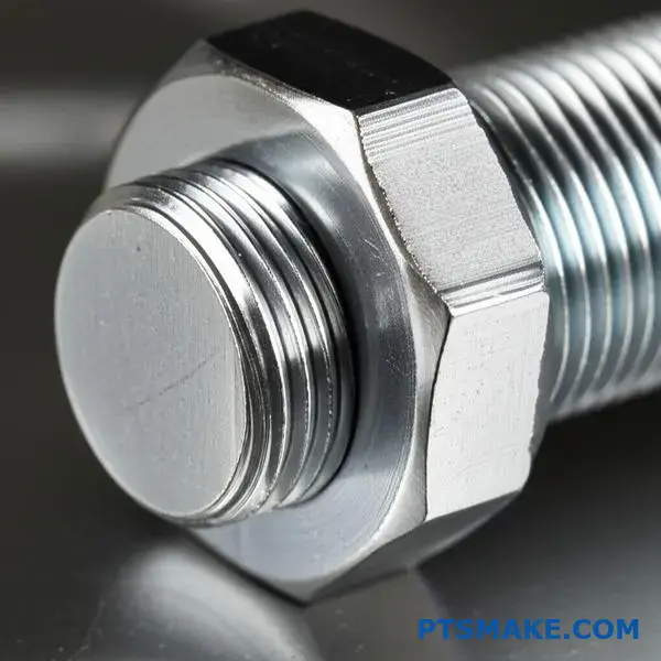
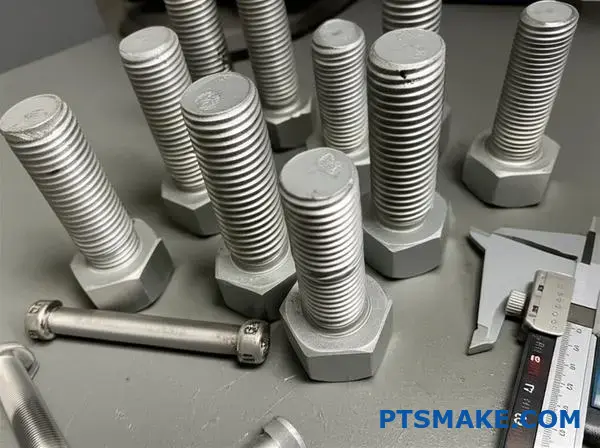
エンジニアは、ねじの公差が重要であることを知っていますが、ほとんどの場合、正しい仕様を選択するのに苦労しています。間違った選択は、組み立ての失敗、生産の遅れ、適切な理解があれば回避できたはずのコストのかかる手戻りにつながります。
ねじの公差は、ねじファスナーの許容寸法限界を定義し、製造上のばらつきを考慮しながら、相手部品間の適切な適合と機能を確保します。公差は、信頼性の高い組立のために、公称寸法からどの程度のずれが許容されるかを規定します。
PTSMAKEでの仕事を通じて、私はネジ公差の決定に基づいてプロジェクトが成功したり失敗したりするのを見てきました。このガイドでは、複雑なねじ公差の世界を、あなたの設計にすぐに応用できる実践的な知識に分解します。
スレッド・トレランスが根本的に解決する問題とは?
なぜ完璧な糸を作ることができないのか、不思議に思ったことはないだろうか。製造業において、完璧は本当の目標ではない。現実には、ばらつきは避けられない。
一貫性への挑戦
2つの部品が本当に同じであることはない。2つの部品には常に微小な違いが存在する。そこで重要になるのが、ネジの許容差という概念です。
機能のフレームワーク
スレッド許容差はスマートな解決策を提供する。一点の完璧な点ではなく、許容範囲を作り出します。これにより、異なる時期に製造された部品、あるいは異なるサプライヤーによって製造された部品であっても、完全に適合することが保証されます。
| コンセプト | 理想の世界 | 実世界 |
|---|---|---|
| 製造業 | パーフェクト・レプリケーション | 必然的な変動 |
| 組立 | 常にフィット | 寛容さが必要 |
第一の原則ばらつきは避けられない
基本的な事実から始めよう。あらゆる製造工程には固有のばらつきがある。CNC機械加工から射出成形に至るまで、小さな偏差は人生の事実である。これが、私たちが受け入れなければならない最初の原則です。
バリエーションはどこから来るのか?
これらの小さな欠陥は、複数の原因から発生する。長い生産期間中の工作機械の摩耗について考えてみよう。あるいは、原材料のロット間のわずかな違いを考えてみてください。工場の温度の変化でさえ、部品の最終的なサイズに影響を与える可能性があります。メンテナンス 寸法安定性1 は常にフォーカスしている。
| 変動要因 | 例 | スレッドへの影響 |
|---|---|---|
| 機械 | 工具摩耗 | ピッチまたは直径のドリフト |
| 素材 | 硬度の変化 | 表面仕上げの変化 |
| 環境 | 温度 | 部品の伸縮 |
| オペレーター | セットアップの違い | 一貫性のない出発点 |
これを管理するシステムがなければ、組み立ては悪夢となる。午前中に作られたボルトが、午後に作られたナットに合わないかもしれない。
コア・ソリューション互換性
これが、ねじ山公差が解決する根本的な問題である。ねじの寸法に明確な「許容範囲」を設定します。部品がこの指定範囲内にある限り、正しく機能します。この原理により、信頼性の高い大量生産が可能になります。PTSMAKEで扱うプロジェクトでは、部品の互換性を保証し、シームレスな組み立てを実現します。
つまり、製造上のばらつきは絶え間ない現実です。ねじ公差は、このばらつきを管理し、部品の互換性を確保し、正しく組み立てるために不可欠なシステムです。
なぜピッチ径が最も重要なねじ寸法なのか?
ピッチ径は、ねじ接続の真髄です。単なる測定値ではなく、2つの部品が実際にどの程度嵌合し、荷重下でどの程度機能するかを決定します。
効果的な接点と考えてほしい。ここからが本当の仕事だ。
接触ゾーン
長径と短径はほぼ境界線である。しかしピッチ径は、フランクとフランクの直接的な表面接触をコントロールする。この接触がフィットの質を決定する。
適切な接触は強度と安定性を保証する。接触不良は故障につながる。
直径の役割比較
| 直径タイプ | 主要機能 | 接続への影響 |
|---|---|---|
| 主要直径 | 最も外側の境界を定義する。 | 組み立てのためのクリアランスを提供する。 |
| 小径 | 最も内側の境界を定義する。 | 根元からの妨害を防ぐ。 |
| ピッチ径 | 側面同士の交戦をコントロールする。 | フィット感、強度、荷重配分を決定する。 |
ねじの嵌合のメカニズム
長径と短径は重要であるが、主にクリアランスを与えるものである。外ねじの長径は、内ねじの短径をクリアする必要があり、その逆も同様です。外径と小径は、ねじの先端(山)や根元で結合することなく、ねじが組み合わされるための空間を作り出します。
しかし、これらの表面は一次引張荷重を支えるようには設計されていない。その重要な仕事は、ねじ山の側面にある角度のついた表面に任されている。
側面の関与が鍵
ピッチ径は、このフランクの噛み合いを直接支配する。これは、ねじ山と溝の幅が等しくなる点でねじ山を通る架空の円柱である。
ボルトとナットのピッチ径がぴったり合うと、互いの側面が均等に押し付け合う。これにより、噛み合ったすべてのねじ山に荷重が均一に分散されます。
適切なかみ合わせは、接続部の引張強度とせん断強度を最大にします。これにより、故障の一般的な原因である、1本のねじ山に応力が集中することを防ぎます。また、次のような問題も防ぎます。 凛々しい2.
公差がフィッティングに与える影響
そのため、ねじの公差はほとんどピッチ径に集中しています。PTSMAKEのプロジェクトでは、この1つの寸法をコントロールすることが、信頼性と再現性の高い接続を実現するために最も重要です。
| ディメンション・デビアンス | 結果として生じる問題 | 結果 |
|---|---|---|
| ピッチ径が大きすぎる | 干渉フィット | 組み立ては難しいか不可能だ。 |
| ピッチ径が小さすぎる | ルーズフィット、過度の遊び | 振動による緩み、強度の低下。 |
| メジャー/マイナー直径オフ | クレスト/ルート干渉 | 軽微なバインディングがあるが、強度に致命的な影響はない。 |
この正確なコントロールが、高性能な接続とストレスで故障する接続を分けるのだ。
ピッチ径は、逃げ面の接触を制御するため、ねじの適合性、強度、および全体的な信頼性にとって最も重要な寸法となります。メジャー径とマイナー径はクリアランスを確保しますが、ピッチ径は、接続部が負荷の下で実際にその役割を果たすことを保証します。
6g/6Hのようなスレッド許容度クラスは何を表しているのか?
スレッド許容度クラスを単純なコードと考えてみよう。このコードには数字と文字の2つの部分があります。それぞれの部分は、製造に関する具体的な指示を与えてくれます。
ナンバー許容等級
数字は公差等級を示す。数字が小さいほど公差が厳しく、より正確であることを意味する。数字が大きいほど、ばらつきが大きくなります。
ほとんどの標準的な用途では、グレード6が最適な選択となる。性能と製造コストのバランスに優れています。
| 公差グレード | 精度のレベル | 一般的な使用例 |
|---|---|---|
| 4 | 非常に高い | 航空宇宙、精密機器 |
| 6 | ミディアム(標準) | 一般エンジニアリング、自動車 |
| 8 | 粗目 | 重要でないファスナー |
手紙基本的逸脱
この文字は、公差ゾーンの開始点を定義する。この文字によって、糸が基本的な理論上のサイズからどれだけ離れているかがわかる。これを基本偏差という。
小文字('g'など)は外ねじ(ボルト)用。大文字('H'など)は内ねじ(ナット)用。
このコードを理解することが、部品の嵌合を成功させる鍵です。PTSMAKEでは、ねじ公差を最初から正しく設定することで、組み立てにかかるコストの問題を未然に防ぐことができると考えています。これは、信頼性の高い機械設計の基礎となる詳細です。
グレードと偏差値がフィットを生む
数字と文字は連動する。これらはボルトとナットの最終的な適合を定義する。等級(数字)はばらつきの窓の大きさを決め、偏差(文字)はその窓の位置を決める。
例えば、ボルトの'g'位置は、許容量を提供する。これは、可能な限り大きなボルトと可能な限り小さなナットの間に保証されたクリアランスがあることを意味します。これにより、部品は干渉することなく簡単に組み立てることができます。
について 基本偏差3 は、互換性を保つために非常に重要である。
一方、'h'ポジションの許容量はゼロである。最大ボルトサイズは基本サイズと同じです。これにより、よりタイトなフィットを生み出すことができる。
一般的な組み合わせとその意味
このシステムでは、さまざまなタイプのフィットが可能です。素早く組み立てるためのルーズフィットや、精密な位置合わせのためのタイトフィットを指定できます。
| コンビネーション | 外ねじ | 内ネジ | フィット感 |
|---|---|---|---|
| 6g/6H | 6g 手当 | 6H (手当なし) | 標準的なクリアランス・フィット |
| 6h/6H | 6h (手当なし) | 6H (手当なし) | トランジション/スナッグフィット |
| 4時間/5時間 | 4h (きつい) | 5H (きつい) | 精密なフィット感 |
過去のプロジェクトでは、適切な組み合わせを選択することが非常に重要でした。私たちは、不必要にコストを押し上げる可能性のある過剰なエンジニアリングを行うことなく、機能性を確保できるクラスを選択するお手伝いをします。
つまり、ねじ公差クラス番号は精度レベルを設定し、文字は公差ゾーンを位置づけます。この2つが合わさることで、相手部品間の意図された適合が正確に定義され、どのような用途においても機能性と製造性の両方が保証されます。
なぜエンジニアはISOやASMEのような規格に頼らなければならないのか?
標準規格は、エンジニアにとって世界共通の言語を生み出す。標準規格は、設計と製造のための共有辞書として機能します。これにより、誰もが同じ技術用語を話すことができる。
普遍的な青写真
この共通言語によって、アメリカのデザイナーは部品を作ることができます。そして、私たちPTSMAKEのような中国のメーカーは、それを完璧に製造することができます。誤解の余地はありません。
重要な要素
この共通理解はすべてをカバーする。材料、寸法、重要な特徴などです。この精度は、プロセスから当て推量とコストのかかるエラーを取り除きます。
| アスペクト | スタンダード | 基準なし |
|---|---|---|
| コミュニケーション | 明確かつ正確 | あいまいで混乱させる |
| 解釈 | ユニバーサル | 主観的&ローカル |
| 成果 | 一貫した品質 | 予測不可能な結果 |

では、この言語がなくなるとどうなるかを探ってみよう。すべての企業が独自のルールを持っている世界を想像してみてほしい。それは、特にグローバル・サプライチェーンにとっては、純粋なカオスとなるだろう。
共通言語なき混沌
単純なM6ネジについて考えてみよう。ISOやASMEの規格がなければ、「M6」という概念は何十種類もの異なるものを意味する可能性がある。そこで、ねじの公差に関する明確なシステムが不可欠となる。
ミスマッチな部品の世界
あるサプライヤーのボルトは別のサプライヤーのナットに合わない。組立ラインは停止してしまうだろう。製造の原理はすべて 相互互換性4 これは単なる不都合ではない。これは単なる不都合ではなく、システムの完全な失敗なのだ。
PTSMAKEの過去のプロジェクトでは、これらの規格に頼ることで、顧客のためにグローバルに部品を調達することができました。ドイツから指定されたファスナーが、中国で機械加工した部品に完璧に適合することは分かっていました。
製造業への波及効果
規格がなければ、コストは爆発的に膨れ上がる。顧客独自の設計のために、独自の工具やゲージが必要になる。リードタイムは数週間から数ヶ月に延びるだろう。
| メートル | スタンダード | 基準なし |
|---|---|---|
| 金型費用 | 標準化された、より低い | カスタム, 非常に高い |
| リードタイムズ | 予測可能 | 予測不可能、長い |
| 品質管理 | ストレート | 複雑でコストがかかる |
| グローバルソーシング | 可能 | 不可能 |
このように管理された環境だからこそ、規格は単なるガイドラインではなく、近代的な製造業の基盤なのである。
ISOやASMEのような規格は、重要な共通言語を提供する。これがなければ、世界の製造業は大混乱に陥るだろう。交換可能な部品が存在しなくなり、コストの高騰、予測不可能なスケジュール、特にネジ公差のような細部に関する製品の不具合が蔓延することになる。
現実的な意味での許容と寛容の対比。
簡単な例えを使おう。ガレージに車を駐車することを想像してほしい。ガレージのドアは穴で、あなたの車はシャフトだ。
意図的なギャップ
アローアンスは 意図的 余分なスペース。ドアの幅と車の幅の差です。この隙間があることで、クルマが側面をこすらずに収まるのです。
避けられない過ち
寛容とは 無作為 しかし、許容できる製造誤差です。あなたのクルマは、スペックシートに書かれているよりも数ミリ幅が広かったり狭かったりするかもしれません。これが製造上のばらつきです。
| コンセプト | 類似性 | 説明 |
|---|---|---|
| 手当 | 余分なスペース | スムーズにフィットするように設計された隙間。 |
| 寛容 | サイズバリエーション | 本番で許されるエラー。 |
フィット感を定義する組み合わせ
許容差と公差は独立したものではありません。両者は互いに協力し合って、嵌合部品の最終的な適合を決定する。許容差は意図された空間を設定し、公差はその空間の許容範囲を定義します。
このように考えてください:許容範囲はあなたの目標であり、公差はその周りの雄牛の目のリングです。最終的な寸法がその輪の中に収まっていれば、その部品は合格です。
サイズの限界
部品の基本寸法、許容差、公差の組み合わせによって、"寸法の限界 "が生まれます。これは、部品が持つことができ、なおかつ機能的であるための最大寸法と最小寸法のことです。これは、特に以下のような精密なフィットを扱う場合には、非常に重要な概念です。 最低の素材コンディション5.
PTSMAKEの仕事では、これらの限界を注意深く管理している。例えば、ネジ部品を含むプロジェクトでは、ネジ公差の管理は、バインディングのない確実な接続を確保するために不可欠です。お客様とのテストの結果、公差をわずかに厳しくすることで、アセンブリの信頼性が15%以上向上することがわかりました。
| エレメント | フィットにおける役割 |
|---|---|
| 基本サイズ | 理論的には完璧な次元。 |
| 手当 | 最小クリアランスまたは最大干渉を定義する。 |
| 寛容 | 1つの部品について、許容できるばらつきの合計を定義する。 |
この相互作用によって、クリアランスフィット、トランジションフィット、干渉フィットのいずれが得られるかが決まる。
許容範囲とは、部品が適合するために計画された隙間のこと。公差とは、許容される製造誤差のことです。私たちが日々実践している原則です。
長径と短径の公差は機能にどのような影響を与えますか?
長径と短径は全く異なる用途に使用される。ねじの公差は互換性がありません。これらのねじは、機能的に異なる課題を解決するために設計されています。
大径部の役割
外ねじの主要直径公差は、主にはめ合いを支配する。これは、ねじが干渉することなく相手部品に入ることを保証します。また、レンチが適切にかみ合うための表面も提供します。
小径の役割
対照的に、内ねじの小径公差は強度にとって非常に重要です。この公差は、適切なタップ・ドリル・サイズを決定し、荷重下での芯材の耐剥離性を規定します。
| 直径タイプ | 主な目的 | 重大な懸念 |
|---|---|---|
| 専攻(外部) | 組立・金型 | 妨害リスク |
| マイナー(内部) | ストレングス&タッピング | 部品の故障 |
この2つの直径の公差は単なる数字ではなく、重要な機能制御です。公差を正しく設定することで、一般的な製造や組み立ての失敗を防ぐことができる。PTSMAKEの過去のプロジェクトでは、この違いが重要な鍵を握っていました。
メジャー直径:干渉とグリップのコントロール
長径の主な仕事は、干渉を防ぐことである。ネジの長径が最大公差の場合、最小公差の穴に入らないことがある。これでは、組立ラインが止まってしまう。
また、工具と締結具の相互作用にも影響します。六角ボルトの場合、フラットを横切る寸法が主要直径となる。ここでの公差が緩いと、レンチの取り付けがずさんになり、角が丸くなって適切なトルクが得られなくなります。
小径:強さの核心
ナットやタップ穴の小径は、その基礎となるものである。この寸法は、タップの前に使用するドリル・ビットのサイズに直接影響する。穴が小さすぎると、タップがバインドして壊れてしまいます。
穴が大きすぎると、ねじ山が浅く弱くなる。これは接続部の強度を著しく低下させる。小径部の材料は、想定される荷重を処理するのに十分でなければならない。ここでのコントロールが悪いと、ねじ山が大きくなる可能性がある。 応力集中6これはボルトの不具合の主な原因である。
| 許容誤差 | 結果として生じる機能的問題 |
|---|---|
| メジャー径が大きすぎる | 部品は組み立てられない。 |
| メジャー径が小さすぎる | 工具のグリップが悪く、滑る危険性がある。 |
| 小径が小さすぎる | 製造中のタップ破損。 |
| 小径が大きすぎる | 糸が弱く剥がれやすい。 |
大径公差は、外径のはめあいを制御し、組み立て時の干渉を防ぎ、工具の確実なグリップを確保します。小径公差は内ねじに不可欠で、タップドリル寸法を決定し、部品の芯強度を破損から守ります。
スレッドのばらつきをゼロにすることが現実的に不可能なのはなぜか?
物理学の観点から言えば、完璧は幻想である。ねじ山のばらつきをゼロにするのは難しいどころか不可能だ。すべての製造工程で、避けられない小さな誤差が生じる。
これらの変動は、核となる物理的限界に起因する。機械、工具、材料、さらには温度変化も考慮しなければなりません。これを理解することで、ねじ公差の現実的な目標を設定することができます。
以下は、理想的なゴールと、私たちが精密製造に取り組んでいる物理的な現実との簡単な比較である。
| アスペクト | 理想(ゼロ・バリエーション) | 現実 |
|---|---|---|
| プロセス | 完璧な安定性と再現性 | 微振動と偏差 |
| 工具 | 不変の寸法 | 使用するたびに磨耗する |
| 素材 | 完全に均一 | 微量不純物を含む |
| 環境 | 一定温度 | 熱による膨張 |
存在しない "完璧な "糸を追い求めることは、非現実的なだけでなく、とてつもなくコストがかかる。
物理学の不屈の法則
なぜこのようなばらつきが製造業の世界の基本的な部分なのかを説明しよう。技術や技能の不足ではなく、物理的な問題なのだ。
製造プロセスの限界
どんな機械も無限の剛性はありません。最先端のCNCマシンでさえ、動作中には微小な振動やたわみがあります。これらの微小な動きは、ほとんど計り知れないが、加工物に直接伝わる。その結果、完璧なねじ山形状から微小なずれが生じる。材料の 異方的挙動7 また、結晶粒の方向によって、切断力に対する反応も異なる。
避けられない道具の摩耗
切削工具が最も鋭くなるのは、最初に切る前だけである。糸を切るたびに、刃先は少しずつ摩耗していく。この摩耗は徐々に進行するが、容赦はない。工具が鈍るにつれ、生み出される糸の寸法も変化する。
ここでは、工具の摩耗が部品のバッチにどのような影響を与えるかを説明する:
| 品番 | 工具の状態 | ピッチ径 |
|---|---|---|
| 部品 #1 | 新しいツール | 目標通り |
| 部品 #500 | マイナーウェア | やや大きめ |
| 部品 #1000 | 中程度の摩耗 | 許容範囲の上限を超える |
PTSMAKEでは、一貫したねじ公差を維持するために、厳格な工具寿命監視と交換プロトコルによってこれを管理しています。
素材の本質
原材料は決して完全に均一ではない。微細な凹凸、硬度のばらつき、内部応力などがあります。工具が材料に切り込みを入れると、これらの不完全性により、材料はわずかに予測できない反応を示します。
熱膨張の隠れた影響
切削による摩擦は大きな熱を発生させる。この熱は、工具とワークピースの両方を膨張させる。熱いうちに測定した部品は、冷めたときとは異なる寸法になります。高精度を達成するためには、このような熱の影響を制御し、補正する必要があります。
その核心は、ばらつきゼロの追求が物理学の基本法則と戦うことである。工具の摩耗、材料の不均一性、機械の振動、熱膨張はすべて固有の現実です。これらの限界を認識することは、現実的で再現可能な精度を達成するための第一歩です。
ISOのメートル法と統一公差系(UN/UNF)を対比する。
スレッドのコールアウトを理解することは非常に重要です。ISOメートル法と統一(UN/UNF)法は、紙の上では異なって見えます。これは、両者が独自の呼称構造を持っているためです。
例えば、一般的なメートル法の表記はM8 x 1.25-6Hである。Unifiedの場合は、5/16-18 UNC-2Bと表示されることがあります。
一目でわかる指定
コードは物語を語る。「6H "と "2B "は、以下のように定義されている。 ねじ許容差.これらは互換性がない。両者はまったく異なるシステム哲学を反映している。
| システム | 外部スレッドの例 | 内ネジの例 |
|---|---|---|
| ISO メトリック | 6g | 6H |
| ユニファイド(UN/UNF) | 2A | 2B |
これらの違いは、部品のフィット感や機能に直接影響します。適切なものを選ぶことが、どのようなプロジェクトにおいても重要な鍵となる。
コードに隠された哲学
ISOシステムは高度に構造化されている。公差等級には数字が使われる。また、位置には文字が使用される。これにより、適合可能性の詳細なマトリックスが作成される。
国連/UNFのシステムは、より階級に基づくものだ。フィットを大まかなカテゴリーに分類している。クラス1、2、3はそれぞれ、ルーズフィット、スタンダードフィット、タイトフィットを定義している。クラス2は一般的な用途で最も一般的です。
デザイナーにとっての実践的意味合い
グローバルに活動するデザイナーは、両方のシステムに精通していなければなりません。アメリカの設計者がクラス2Bのはめ合いを指定する場合、ISOの同等規格が必要です。通常、6Hが内ねじに最も近い。
しかし、これらは同一ではありません。PTSMAKEの過去のプロジェクトでは、ミスマッチが組み立ての問題を引き起こしているのを目にしてきました。このような公差ゾーンの微妙な違いが重要なのです。ISOシステムは、以下のような方法で、よりきめ細かなコントロールを提供します。 基本偏差8.
以下は、一般的なフィットアプリケーションの比較である:
| フィット・クラス | システム | 代表的なアプリケーション |
|---|---|---|
| ルーズフィット | 1A/1B(UNF)、7H/7g(ISO) | 組み立てが簡単で、破片が散乱しにくい |
| スタンダード・フィット | 2A/2B(UNF)、6H/6g(ISO) | 汎用業務用 |
| タイト・フィット | 3A/3B(UNF)、4H/5g(ISO) | 高精度、ゼロクリアランス |
この翻訳は、当社のDFM(製造可能設計)サービスの重要な部分です。元の図面で使用されているシステムに関係なく、設計意図が維持されるようにします。
ISOおよび国連システム・ラベル ねじ許容差 は異なる(例:6Hと2B)。これらのコードは、1つはシステマティック、もう1つはクラスベースという異なる哲学に由来する。グローバルなプロジェクトでは、これらの違いを理解することが、組み立てミスを防ぎ、部品が適切に機能するために不可欠です。
結論用途に応じた正しい選択
クラス2Aとクラス2Bのスレッドを選ぶのは簡単だ。適合性と機能性による。覚えておいてほしいのは、2Aは外ねじ(ボルト、ねじ)用だということだ。クリアランスが確保される。
この小さな許容差は、コーティングやメッキに最適です。クラス2Bは、内ねじ(ナット、ねじ穴)用です。余分なクリアランスのない標準的なはめあいを提供します。
クイック・リファレンス・ガイド
この表は、意思決定プロセスを簡素化します。あなたのデザインを素早くチェックするためにお使いください。
| クラス | スレッドタイプ | 主な特徴 | 一般的な使用例 |
|---|---|---|---|
| 2A | 外部 | 手当て(クリアランス) | メッキまたはコーティングされたネジ |
| 2B | 内部 | 手当なし | 標準ナット、タップ穴 |
この区別は部品組み立ての基本である。
最終的に、その選択は製造工程全体に影響を与える。図面上の単純な表記が、製造と検査へのアプローチ方法を決定するのです。PTSMAKEの過去のプロジェクトでは、このディテールの見落としが、いかに組立工程で重大な問題を引き起こすかを目の当たりにしてきました。
基本を超える:製造業への影響
指定されたねじ山の公差は、工具の選択と品質管理に直接影響します。例えば、コーティングを厚くする場合、最終的な2Aのねじ山が2Bのねじ山と正しく嵌合するよう、慎重に計算する必要があります。これは数字だけの問題ではなく、実際的な結果なのです。
そこで重要なのが、製造パートナーとの明確なコミュニケーションです。私たちは、クライアントが初期設計以外の要素も考慮できるよう支援します。これには、材料の選択や後加工のステップが含まれます。私たちの経験から、適切な ゲージ校正9 は、安定した結果を出すために譲れない。
決断を左右する要因
スレッドクラスを指定する際には、これらの点を考慮してください。それぞれが最終的なパーツの性能とコストに関与する。
| ファクター | 2A/2B選択への配慮 |
|---|---|
| 後処理 | 部品はメッキ、アルマイト、コーティングされますか?はい」の場合、2Aが必要です。 |
| アッセンブリーフィット | 標準的で信頼できるフィット感で十分?2Bがお勧めです。 |
| 環境 | 腐食は要因になるか?2Aで保護されたコーティングが役立ちます。 |
| コスト | クラス2のスレッドは、性能と製造性の素晴らしいバランスを提供します。 |
これらの要因について早期に話し合うことで、コストのかかる手戻りや遅れを防ぐことができる。
クラス2Aとクラス2Bのねじ山を正しく選択することで、特に後加工後の適切な適合が保証されます。これは、組み立てと機能を成功させるための重要なディテールです。正しいねじ公差を実現するためには、私たちPTSMAKEのようなメーカーとの明確なコミュニケーションが不可欠です。
公差クラスはどのようにして異なるメカニカルフィットを生み出すのか?
メカニカル・フィットは精密工学の心臓部です。2つの部品がどのように組み合わされ、機能するかを定義します。穴とシャフトの関係がすべてです。
フィットには主に3つのタイプがある。それぞれ、特定の公差クラスの組み合わせによって作成されます。これらによって、最終的なアセンブリの動作が決定されます。
クリアランス
ここで、シャフトは常に穴より小さい。これにより、部品間のスペースが保証される。これらは自由に動いたり回転したりすることができる。H7/g6の組み合わせは典型的な例である。
トランジション・フィット
これが中間点だ。穴とシャフトの公差は重なっている。最終的な組み立てでは、わずかなクリアランスやわずかな干渉が生じるかもしれない。ここではH7/k6が一般的な選択です。
干渉フィット
この場合、シャフトは常に穴より大きい。部品を組み立てるには力が必要です。これにより、強固で固定された接続が生まれます。H7/p6は典型的な干渉嵌合です。
フィット・アプリケーションを深く掘り下げる
正しいフィットを選ぶことは非常に重要です。性能、組み立て、コストに直接影響します。PTSMAKEのプロジェクトでは、この決定が設計検討プロセスの重要な部分を占めています。
クリアランス・フィットの実用化(H7/g6など)
重荷重のかからない回転軸の単純なベアリングを思い浮かべてください。潤滑と自由回転のためにクリアランスが必要です。このはめあいにより、ベアリングのインナーレース内でシャフトが拘束されることなく回転できるようになります。組み立てと分解が簡単なのも利点です。
トランジション・フィットを使用する場合(例:H7/k6)
トランジション・フィットは正確な位置決め用です。大きな力を必要とせず、ぴったりと組み立てることができる。シャフト上のギアやプーリーを考えてみよう。これらは正確に位置決めする必要がありますが、メンテナンスのために取り外す必要がある場合もあります。このフィットは、そのバランスを提供します。同じような原理が ねじ許容差10 ファスナーが正しく配置されていることを確認するため。
干渉の力 フィット(H7/P6など)
干渉フィットは、強力で永久的なアセンブリを作成します。キーやピンを使わずにトルクを伝達したり、重荷重に耐えることができる。一般的な例は、硬化したスチールピンを柔らかいハウジングに押し込むことです。部品は弾性的に変形し、莫大な圧力と摩擦を生み出す。
| フィット・タイプ | 組み合わせ例 | 代表的なアプリケーション | 組み立てノート |
|---|---|---|---|
| クリアランス | H7/g6 | ジャーナルベアリング内のシャフト | 部品は互いにスライドする |
| トランジション | H7/k6 | 位置決めダボピン、スピゴット | 軽い力が必要 |
| 妨害 | H7/p6 | ハウジングへのベアリング | 圧入が必要 |
これら3つのはめあいタイプを理解することが基本です。穴とシャフトの公差クラスを正しく選択することで、部品が自由に動くか、正確に位置決めされるか、永久にロックされるかを正確に制御することができます。
メッキやコーティングは、ねじの公差にどのような影響を与えますか?
メッキまたはコーティングは、材料の薄い層を追加します。この層が、部品の最終的なサイズを大きくする。ネジの場合、これは非常に重要な問題です。
この追加された材料は、計画されたスペースを消費する。このスペース(取り代)によって、部品がスムーズに組み合わされる。
適切な計画を立てないと、ネジ山が組み合わされないことがある。はめ合いがきつくなりすぎて、干渉が生じます。これはねじ山の公差に直接影響します。
厚みがもたらす影響
数ミクロンのメッキでも問題になることがあります。下の表は、コーティングの違いによるフィットへの影響を示しています。
| コーティング・タイプ | 代表的な厚さ (μm) | 妨害リスク |
|---|---|---|
| 亜鉛メッキ | 5-15 | ミディアム |
| 無電解ニッケル | 10-25 | 高い |
| 陽極酸化処理(タイプII) | 5-18 | ミディアム |
そのため、最初からコーティングの厚みを考慮しなければならない。
規格がメッキのパズルを解く方法
では、どうすればこの干渉を防ぐことができるのか?コーティングの厚みを無視するわけにはいかない。
ISOのような標準化団体は、スマートな解決策を提供している。ISOのような規格団体は、コーティングされる部品に異なるネジ公差クラスを規定しています。
この方法は、糸のスタート位置を変える。将来のコーティングのためのスペースを効果的に作ることができる。
コーティングされていない外ねじの場合、「h」位置が一般的である。これは、許容誤差がゼロであることを意味する。これは、ねじの最大サイズが基本サイズであることを意味する。
しかし、メッキ用のねじ山には、「g」ポジションが使用される。これにより、メッキが施される前に、ビルトイン・ギャップが形成される。
このギャップは 基本偏差11は、コーティングの厚みに合わせて設計されている。
メッキ前とメッキ後の寸法比較
目標は単純だ。メッキを施した後、『g』ポジションのネジ山は、標準的な『h』ポジションのネジ山と同じようにフィットしなければならない。
| スレッドポジション | 手当 | 使用目的 | 最終フィット(メッキ後) |
|---|---|---|---|
| h | ゼロ | コーティングなし | 該当なし |
| g | ポジティブ | メッキ/コーティング | 6hに類似 |
PTSMAKEでの実践
PTSMAKEでは、常に設計の初期段階で表面仕上げについて話し合います。メッキ前のネジ公差が正しく指定されていることを確認します。
このプロアクティブなステップにより、コストのかかる手戻りを防ぐことができる。また、部品が正しく組み立てられないことによる遅延も防ぐことができます。
コーティングによって厚みが増すと、ねじの適合性が損なわれる可能性があります。これを解決するために、規格では特別なプレメッキ公差クラスを使用しています。これらのクラスは、外ねじ用の「g」のように、コーティングのためのスペースを確保するための初期ギャップを作り、適切な組み立てを保証します。
Go/No-Goゲージのシステムとは?
Go/No-Goゲージは単なる検査ツールではありません。部品の公差限界を物理的に表現するものです。設計図面を直接、物理的にテストするものとお考えください。
Go」側は、許容できる最小のフィーチャーサイズを確認する。フィットしなければならない。逆に「No-Go」側は、許容可能な最大サイズを表します。適合してはならない。
このシンプルなバイナリーシステムは、当て推量を排除します。合格か不合格かを明確に判定し、すべての部品が要求されるねじ公差に適合していることを保証します。
Go/No-Goシステムの優雅さは、抽象的な数値を物理的なチェックに直接変換するところにあります。部品のねじ公差は、上限と下限の境界によって定義され、ゲージはこれらの境界条件に合わせて正確に加工されます。
ゴー」ゲージ組み立ての確認
ゴー」ゲージは、ねじの最大材料条件(MMC)に合わせて製造される。ナットのような内ねじの場合、これは最小許容ピッチ径に相当します。
ゴー」ゲージがスムーズにねじ込まれれば、その部品が対応する相手と組み合わされることが保証される。部品が小さすぎないことも確認できる。
ノー・ゴー」ゲージ適切なフィット感の確保
ノー・ゴー」ゲージは、最小材料条件(LMC)をチェックする。内ねじの場合、これは最大許容ピッチ径です。ねじ山が緩みすぎていないことを確認します。
このゲージが部品の中に入ってはならない。この重要なチェックにより、十分なねじの噛み合いが保証されます。これらのゲージの設計と使用は、次のような基本コンセプトに従っています。 テイラーの原理12.
PTSMAKEの品質管理プロセスにおいて、これは基本的なステップです。これにより、私たちがお届けするCNC加工部品が、お客様の求める精密なねじ公差に適合していることが保証されます。
| ゲージタイプ | この条件をチェックする | 目的 | 良いパーツの結果 |
|---|---|---|---|
| 囲碁ゲージ | 最大素材条件(MMC) | 部品が組み立てられることを確認する | マスト・フィット |
| ノー・ゴー・ゲージ | 最低材料条件(LMC) | 部品が緩みすぎていないことを確認する | 適合しないこと |
Go/No-Goゲージは、部品のねじ公差を物理的に具現化します。ゴー」ゲージは、組み立てのための最大材料条件を確認し、「ノーゴー」ゲージは、確実な取り付けと緩みによる不具合を防ぐための最小材料条件を確認します。
素材の選択は公差の選択にどのような影響を与えるのか?
材料の選択は、単に強度と重量だけではありません。材料固有の特性は、実用的かつコスト効率よく達成できる公差に直接影響します。
延性と機械加工性
延性の高い材料は、切削圧力で変形することがあります。このため、超精密な公差を達成することがより複雑になり、加工時間が長くなる可能性があります。
熱膨張の懸念
材料は温度変化によって膨張したり収縮したりする。アルミニウムと鋼鉄のような異なる材質の部品を組み合わせるには、慎重な配慮が必要です。
| 素材 | 熱膨張係数 (ppm/°C) |
|---|---|
| アルミニウム | ~23 |
| スチール | ~12 |
この不一致は、結合や故障を防ぐために、意図された使用環境を考慮した公差が必要であることを意味する。
マテリアル・ビヘイビアの深層
現実的な公差を設定するためには、加工中および最終用途での材料の挙動を理解することが重要です。過剰なエンジニアリングとコストのかかる不具合を防ぐことができます。
延性が精度に及ぼす影響
一部のアルミニウム合金のような延性のある材料は、機械加工中に長くて筋のような切りくずを作ることがあります。これは工具に巻き付き、部品の表面を傷つける可能性があります。PTSMAKEでは、これを軽減するために送りや速度を注意深く制御していますが、非常に厳しい公差を定義する際には重要な要素となります。
ギャリングの挑戦
ステンレス・スチールのような素材は、その傾向が強い。 凛々しい13この場合、表面は圧力下で本質的に溶接される。これはファスナーにとって重要な問題である。ねじ公差をわずかに緩くすることで、焼き付きを防止するために必要なクリアランスを確保することができ、部品の組み立てと分解を確実に行うことができます。
アセンブリの熱管理
過去のプロジェクトでは、熱膨張を無視したためにアセンブリが故障するのを見たことがある。室温ではアルミ製ハウジングにぴったりフィットしていたスチール製シャフトが、使用温度が高くなると完全に固着してしまうことがあります。公差は、全機能温度範囲に対して設計されなければなりません。
| プロパティ | 素材例 | 許容範囲の推奨 |
|---|---|---|
| 高い延性 | 銅 | 公差が緩い方が費用対効果が高いかもしれない。 |
| ギャリング傾向 | ステンレス鋼 | 特にスレッド公差については、より緩いスペックを検討すること。 |
| 高い熱膨張率 | プラスチック、アルミニウム | 全使用温度に対する許容誤差を計算する。 |
| 脆さ | 硬化鋼、セラミック | より厳しい公差が可能だが、破断のリスクは高まる。 |
延性、熱膨張、カジリなどの材料特性は単なるデータポイントではなく、設計上の制約条件です。公差の選択が成功するかどうかは、部品がそのライフサイクルを通じて正しく確実に機能し、予防可能な不具合を回避できるように、これらの挙動を理解できるかどうかにかかっています。
適切なねじ公差を選択するためのプロセスを概説する。
適切な糸公差を選択することは複雑に感じられる。しかし、それは論理的なプロセスです。それは、部品の仕事と製造方法を一致させることです。体系的なアプローチは、過剰なエンジニアリングを防ぎ、コストをコントロールします。
明確なステップ・バイ・ステップのガイドをご紹介します。これにより、毎回正しい決断ができるようになります。わかりやすく、管理しやすいステップに分けましょう。
機能的ニーズから始める
まず、スレッドが何をしなければならないかを定義する。簡単に組み立てることが最優先か?それとも絶え間ない振動に耐える必要があるのか?それぞれの機能は、異なる許容レベルを指している。
| 機能要件 | 典型的な許容目標 |
|---|---|
| 簡単・迅速な組み立て | より緩い公差(例:6g/6H) |
| 耐振動性 | より厳しい公差(例:4g6g/4H5H) |
| 高強度ファスナー | ミディアム・タイト・トレランス |
| シーリング用途 | シーラントによるより厳しい公差 |
緩いフィットは迅速な生産に適しています。タイトフィットは、ストレス下での信頼性を保証します。
次に、製造工程とその影響について考えなければならない。糸を作るために使われる方法は、達成可能な精度と最終的なコストに直接影響する。これは非常に重要なバランス感覚である。
製造とコストを考える
選択した製造工程が現実的な限界を設定します。PTSMAKEが得意とするCNC機械加工は、厳しい公差に対して高い精度を提供します。しかし、ねじ転造や成形のような方法は異なります。
より厳しい公差は、より精密な機械加工を要求します。これは、より多くの機械加工時間、専用工具、厳格な検査を意味する。これらはすべてコストに上乗せされる。重要なのは、その余分なコストが実際の性能に利益をもたらすかどうかを問うことです。私たちのプロジェクトでは、公差は不必要に厳しいものよりも、多少緩くても一貫性のあるものの方が優れていることがよくあります。
環境要因
その部品はどこで使用されますか?高温は材料の膨張を引き起こす可能性があります。腐食性の環境は、ねじ山の表面に影響を与える可能性があります。このような要因によって、ねじの適合性や経時的な性能が変化する可能性があります。材料の選択はここでも重要です。
最終的な公差クラスの選択
これらの情報をもとに、特定の公差クラスを選択することができます。この決定は、機能、製造性、コストのバランスを取る必要があります。単に最も厳しいオプションを選ぶということではありません。用途に最も適したものを選ぶということなのです。適切な ゲージの反復性と再現性14 どのクラスを選択しても、確実に検証できることを保証する。
| ファクター | より緩い許容範囲 | より厳しい公差 |
|---|---|---|
| 組立速度 | より速く | 遅い |
| 振動ロック | より低い | より高い |
| 製造コスト | より低い | より高い |
| 採寸の難しさ | より簡単に | より複雑な |
この構造化されたプロセスは、一般的なニーズから、具体的で正当化可能な糸公差の選択へと移行します。
明確な意思決定プロセスが重要です。機能、製造、コスト、環境を評価することで、性能要件と予算のバランスが取れた最適なねじ公差を自信を持って選択することができ、プロジェクトを成功に導きます。
正しい検査ゲージの選び方は?
図面のコールアウトを解釈することが最初のステップである。それが検査計画全体を決定する。正確な言語なのだ。
このプロセスにより、すべての部品が仕様に適合することが保証される。どのゲージをツールクリブから引き抜くかを正確に指示します。
下記はクイックガイドです。図面上のフィーチャーが特定のゲージタイプにどのように変換されるかを示しています。
| ドローイング特集 | 必要なゲージ・タイプ |
|---|---|
| M8x1.25-6Hスレッド | スレッドプラグゲージ |
| Ø10.00 H7ホール | プレーンプラグゲージ |
| Ø25.00 g6 シャフト | Go/No-Goプレーンリングゲージ |
このシステマティックなアプローチは、当て推量を排除する。一貫した品質管理の基礎を築きます。
ゲージ選択の実践的手順
PTSMAKEでは、明確な手順に従っています。これにより、すべての機能に対して適切なツールを選択することができます。それは設計図面から始まります。
ステップ1:コールアウトの解読
まず、コールアウトを詳細に分析します。呼び径、ピッチ、重要なねじ公差を特定します。この情報がゲージ選択の青写真となります。完璧にフィットさせるためには、細部に至るまで重要です。
ステップ2:作業ゲージの選択
呼び出しを基に、使用するゲージを選択します。内ねじには、Go/No-Goねじプラグゲージを使用します。外ねじの場合は、ねじリングゲージを使用します。
| パート特集 | 作業ゲージ | 目的 |
|---|---|---|
| 内ネジ | スレッドプラグゲージ | 最小ピッチ径と最大ピッチ径をチェック |
| 外ねじ | スレッドリングゲージ | スレッドプロファイルとサイズを確認 |
| プレーンホール | プレーンプラグゲージ | 穴の直径が許容範囲内であることを確認する |
| シャフト/ピン | プレーンリングゲージ | シャフトの直径が許容範囲内であることを確認 |
ステップ3:ゲージの検証を忘れずに
スレッドリングゲージには、常にマスターを使用します。 チェックプラグ15.これらのプラグは、リングゲージ自体が正確で、摩耗していないことを確認します。品質保証の重要なステップです。
ステップ4:ゲージだけでは不十分な場合を知る
ゲージでは不十分な場合もあります。公差が非常に厳しい部品や複雑な形状の部品、あるいは重要な安全機能を持つ部品については、さらにエスカレーションを行います。三次元測定機、光学式コンパレーター、ビジョンシステムなどの高度なツールを使用して、より詳細な分析を行います。
この決定はリスクに基づいている。もし故障が致命的なものであれば、私たちは利用可能な最も精密な測定方法を使用します。
正しい検査ゲージの選択は、規律正しいプロセスです。それは、図面のコールアウトを注意深く読み、作業ゲージと検証ツールを体系的に選択することから始まります。ゲージの限界と、高度なCMMや光学検査を使用するタイミングを知ることは、総合的な品質保証にとって非常に重要です。
公差を厳しくすることは、製造コストにどのような影響を与えますか?
公差等級とコストの関係は直線的ではなく、指数関数的である。粗い公差から細かい公差に移行すると、費用は劇的に増加する。
これは小さな値上げではない。製造プロセスの根本的な転換なのだ。
耐性グレード・コスト曲線
一般的な糸の許容範囲を考えてみよう。標準的な8gから細かい4gにシフトするには、まったく異なるアプローチと予算が必要になる。
簡略化した内訳はこうだ:
| 特徴 | 粗い許容差(例:8g) | ファイン・トレランス(例:4g) |
|---|---|---|
| マシンタイプ | 標準CNC | 高精度CNC |
| 生産スピード | より速く | 遅い |
| コストへの影響 | ベースライン | かなり高い |
公差を厳しくするための一歩一歩が複雑さを増し、その結果コストがかかる。

より微細な公差グレードへの移行は、生産の各段階に影響を与えます。PTSMAKEでは、このような影響を通じて、精度とコストのバランスを見つけるよう、パートナーを指導しています。
機械と工具の需要
標準的なCNCマシンは、8gのスレッドには完璧かもしれない。しかし、ねじの公差が4gの場合は、より高級な機械が必要になることが多い。これらの機械は、より高い安定性と精度を提供しますが、割高なコストがかかります。
工具も要因のひとつだ。厳しい公差を維持するためには、工具を頻繁に交換しなければならない。工具の磨耗は速く、わずかな磨耗でもパーツを規格外に押し出す可能性がある。これは、新しい工具への出費と、交換のための機械停止時間の増加を意味する。
生産とスクラップ率の影響
精密さには忍耐が必要です。より微細な仕上げを実現し、厳しい公差を保持するためには、機械はより遅い速度と送りで運転しなければなりません。これは、パーツあたりのサイクルタイムを直接的に増加させます。
エラーのマージンも劇的に縮小する。わずかな振動や温度変化が不合格品につながる可能性があります。当社のプロジェクトデータによると、非常に微細な公差に移行すると、スクラップ率が2%以下から5%以上、あるいはそれ以上に増加する可能性があります。すべてのスクラップ部品は、材料、機械時間、労働力の無駄となります。また、検査工程自体もより集中的になり、多くの場合、高度な検査技術が必要になります。 計測16 道具を使う。
| コストドライバー | 粗い公差の影響 | ファイン・トレランス・インパクト |
|---|---|---|
| 加工時間 | 低い | 高(低速) |
| 金型費用 | スタンダード | 高い(頻繁な変更) |
| 検査費用 | 基本チェック | 高度な機材が必要 |
| スクラップ率 | 通常 < 2% | よくある質問 > 5% |
公差等級を厳しくすると、コストが大幅に上昇する。これは、より良い機械が必要になり、工具交換の頻度が増え、生産速度が遅くなり、スクラップ率が高くなるためである。精度と予算のトレードオフであり、慎重な検討が必要である。
社内標準はどのように作るのか?
企業独自のガイドを作成することは不可欠です。これによって、デザイン・チームの手間を省くことができます。これによってミスが減り、生産が効率化される。
シンプルなテンプレートは大きな違いを生む。公差へのアプローチを最初から標準化することができます。
ガイドの出発点
このガイドでは、アプリケーションのタイプをデフォルトのトレランスクラスにリンクさせる。これにより、チームの全員が同じページにいることが保証される。
ここに基本的な枠組みがある:
| 応募カテゴリー | 推奨許容差クラス | 例 |
|---|---|---|
| 非重要部品 | ルーズ(ISO2768-cなど) | 外部カバー、化粧パネル |
| 一般的なフィット感と機能 | ミディアム(例:ISO 2768-m) | ブラケット、構造サポート |
| 精密・嵌合部品 | ファイン(ISO2768-fなど) | 位置決めピン、圧入部品 |
この構造は、デザイナーにとって明確で即座の指針となる。
アプリケーション・カテゴリーの詳細
本当の価値は、これらのカテゴリーを拡大することから生まれる。それぞれのクラスに何が当てはまるかを定義しなければならない。そうすることで、曖昧さを防ぐことができる。
非重要部品
これらの部品は通常、耐荷重性や精密なインターフェイス機能を持たない。装飾的なカバーやシンプルなエンクロージャーを思い浮かべてください。ここでより緩い公差を使用することで、最終製品の機能に影響を与えることなく、製造コストを大幅に削減することができます。
構造部品と機能部品
これは幅広いカテゴリーである。取り付けブラケットから内部のサポートフレームまで、あらゆるものが含まれる。一貫性が重要です。ボルトで結合される部品の場合、ネジ公差を標準化することは、信頼性の高い組み立てと性能を確保するために特に重要です。
精密位置決め機能
これらは最も重要な部分です。製品全体のアライメントと組み立てを決定します。ダボピンの穴やベアリングシートのような特徴は、厳密な管理が必要です。これにより、完璧な 相互互換性17 これは、最初の組み立てと後の修理の両方に不可欠である。
PTSMAKEでは、これらの分類についてお客様にアドバイスすることがよくあります。私たちの機械加工の経験は、設計意図と製造現実のギャップを埋めるのに役立ちます。
| 機能例 | 応募カテゴリー | 推奨ISOグレード | 根拠 |
|---|---|---|---|
| 外部ハウジング | ノンクリティカル | IT12 - IT14 | 美しさは重要だが、フィット感は正確ではない。 |
| 取付穴パターン | 構造と機能 | IT9 - IT11 | 相手部品とのアライメントを確実にする。 |
| ベアリングボア | 精密位置決め | IT6 - IT7 | 適切な操作のためには特殊な装着が必要。 |
| ダボピン穴 | 精密位置決め | IT5 - IT6 | アセンブリの正確なアライメントに不可欠。 |
明確に定義された公差ガイドは強力なツールです。設計を標準化し、ミスを減らし、本当に必要なところだけに精度を適用することで製造コストをコントロールするのに役立ちます。これにより、より一貫性のある信頼性の高い製品が生まれます。
ねじ公差の間違いによる製品の不具合を分析する。
製品の不具合は大きな代償を伴う。スチール製ハウジングのアルミ製ネジ山が剥がれた場合を考えてみよう。この問題は小さいように見えるが、組立ライン全体を停止させる可能性がある。
根本的な原因が1つのエラーであることは稀である。多くの場合、さまざまな要因が絡み合っている。ネジ山の公差不良は大きな要因の一つである。しかし、材料の選択と組立力も重要な役割を果たします。
失敗の要因を分解してみよう。
| ファクター | 説明 | インパクト |
|---|---|---|
| 寛容 | スレッド間の不適合 | 高い |
| 材料 | 硬度/強度の不一致 | 高い |
| トルク | 組み立て時に過度の力がかかる | 高い |
この分析では、これらの要素がどのように組み合わさって致命的な故障を引き起こしたかを示す。
より深く見る:根本原因分析
過去のプロジェクトで、ある顧客がまさにこの問題に直面した。鉄骨フレームにねじ込まれたアルミニウム部品が何度も破損したのだ。私たちの調査では、相互に関連する3つの原因が指摘されました。
素材のミスマッチ
まず、素材が理想的なパートナーではなかった。アルミニウムはスチールよりもはるかに柔らかい。力を加えると、柔らかいアルミニウムのネジ山が最初に変形し、剥がれる。これは、しばしば見落とされがちな基本的な設計上の考慮点である。
スレッド公差の不具合
指定されたねじ山の公差が緩すぎた。そのため、ねじのかみ合わせが不十分だった。負荷がかかると、力はわずかなねじ山に集中した。この数少ない接触点が応力に耐えられず、剥離につながった。異種材料間の相互作用もまた、以下のような影響を受けた。 熱膨張係数18.
過度の組立トルク
最後に、組み立て説明書にはスチール同士の接続に適したトルク値が指定されていた。このトルクは、柔らかいアルミニウムのネジ山には高すぎた。この過剰な力が、ねじ山を完全にせん断する最終的な原因となった。
| 根本原因 | 分析 | ソリューション |
|---|---|---|
| 素材の選択 | アルミニウムはスチール製ハウジングには柔らかすぎる。 | アルミニウム部分にスチール製インサート(ヘリコイルなど)を使用する。 |
| ネジ公差 | 公差が緩いため、荷重配分が悪くなった。 | ネジ山のかみ合わせを良くするため、公差をきつくする。 |
| 組立トルク | トルク仕様がアルミ製には高すぎた。 | 再計算して低いトルク値を指定する。 |
このシステマティックな分析により、PTSMAKEはクライアントに信頼できるソリューションへの明確な道筋を提供することができました。
このケースは、製品の失敗は連鎖反応であることを示している。不適切なねじ公差、不適切な材料選択、誤った組み立てトルクが、完璧な嵐を引き起こした。たった一つの弱点が設計全体を危うくしたのだ。
航空宇宙アセンブリにおけるねじの選択を分解する。
航空宇宙分野では、すべての部品が重要です。高性能のボルトジョイントを調べてみよう。ここでの選択は恣意的なものではありません。意図的な技術的決断なのです。
特定の組み合わせに焦点を当てる。これには、UNJFスレッドフォーム、厳しい公差クラス、特殊コーティングが含まれます。
これらの要素は連動しています。これらの要素が連動することで、ジョイントは安全性、重量、そして長期的な信頼性という極限の要求を満たすことができるのです。小さなディテールが大きな違いを生む
| 特徴 | 標準ボルト | 航空宇宙用ボルト |
|---|---|---|
| スレッドフォーム | 国連 | UNJF(丸根) |
| 寛容 | クラス2A/2B | クラス3A/3B |
| 素材 | 合金鋼 | チタン / インコネル |
| コーティング | 亜鉛メッキ | シルバー/ドライフィルムルーブ |
UNJFスレッドフォームの優位性
UNJFスレッドを選ぶ理由J」が鍵です。これは、外ねじの根元半径が制御されていることを意味します。この丸みを帯びた根元は、ささいなことではありません。ねじ山の最も弱い部分における応力集中を大幅に軽減します。
この設計は、ファスナーの疲労寿命を直接改善します。航空宇宙分野では、部品は何百万回もの振動サイクルに耐えます。標準的なUNねじのような鋭い根元は、疲労亀裂の起点となります。UNJF設計はこれを防ぎます。
究極の信頼性のための厳しい公差
次に ネジ公差.航空宇宙用ジョイントは、ほとんどの場合、クラス3A/3Bの適合を使用する。これは、一般的なクラス2A/2Bよりもはるかに厳しい公差です。きついはめあいにより、ボルトとナットのねじ山の表面接触がより確実になります。
この改良された接触により、荷重がより均等に分散される。摩耗につながるわずかな動きも防ぐことができる。時間が経つにつれ、このような動きは次のような問題を引き起こす可能性がある。 フレッティング腐食19これは接合部の完全性を損ないます。PTSMAKEでは、このような精密な公差を達成することが、航空宇宙産業のお客様向けのCNC機械加工サービスの中核となっています。
| 許容範囲クラス | フィット説明 | 代表的なアプリケーション |
|---|---|---|
| 1A/1B | ルーズフィット | 迅速な組み立て、汚れた状態 |
| 2A/2B | スタンダード・フィット | ほとんどの市販品 |
| 3A/3B | タイト・フィット | 高ストレス、高信頼性 |
先進コーティングの役割
最後に、コーティングは見た目だけではありません。この例では、チタン製のボルトに銀メッキが施されています。これには重要な目的があります。固体潤滑剤として機能するのです。
これにより、ナットとの嵌合時のカジリを防止します。また、導電性を高め、腐食から保護します。コーティングは、特定の環境や機械的な課題に応じて選択される機能的な表面処理です。
高性能な航空宇宙用ジョイントでは、あらゆる機能が最適化されています。UNJFスレッドフォーム、タイト ネジ公差と高度なコーティングが不可欠である。これらは、疲労寿命を最大化し、信頼性を確保し、高い強度重量比を維持するために選択される。
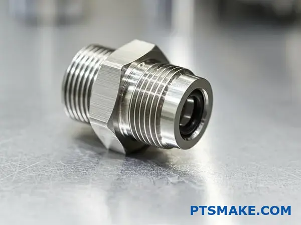
高圧油圧フィッティングのねじ接続を設計する。
すべてをまとめるには、明確な戦略が必要です。高圧的なフィッティングの設計は、ひとつの選択で決まるものではない。3つの重要な要素がいかに協調して機能するかということなのです。
ネジの形状、材質、公差の仕様を正当化する必要があります。これらの決定により、過酷な条件下でも漏れのないシールが保証されます。
コア・ディシジョン・トリオ
スレッドフォームの選択
ここでの選択が土台を作る。それは主要なシーリングメカニズムを決定する。
| 特徴 | NPTF(ドライシール) | SAE Oリングボス |
|---|---|---|
| シール方法 | スレッドの変形 | エラストマーOリング |
| 耐振動性 | フェア | 素晴らしい |
| 再利用性 | 限定 | 高い |
素材と公差
この2つは密接に関連している。材料は圧力に耐えなければならず、一方、公差はシールが正しく係合することを保証する。
堅牢なシールの設計を正当化する
複雑な問題を解決しよう移動式油圧システムのフィッティングを想像してみてください。この継手は、高い圧力スパイクと絶え間ない振動に直面します。
スレッドフォームの選択SAE Oリングボス
この用途では、SAE O-リングボス(ORB)を選ぶ。ネジ山の変形によってシールするNPTFネジとは異なり、ORBはOリングを使用します。これにより、振動による漏れに対して優れた耐性を発揮する。より信頼性の高い長期的なソリューションだ。
Oリングは、制御された 弾性変形20 は、継手面に対してポジティブなシールを維持します。そのため、金属同士のシールよりもはるかに耐久性があり、再利用が可能です。
素材の選択316ステンレススチール
材料の選択は非常に重要です。炭素鋼は一般的ですが、腐食の影響を受けやすく、シール面を損なう可能性があります。
| 素材 | 定格圧力 | 耐食性 |
|---|---|---|
| 炭素鋼 | 高い | フェア |
| 316ステンレス鋼 | 非常に高い | 素晴らしい |
| 真鍮 | ミディアム | グッド |
私は316ステンレスを推奨する。その優れた耐食性は、Oリングが効果的にシールするために必要な精密機械加工面を保護します。また、高い圧力にも故障なく対応できる強度も備えています。
ねじ公差の指定
最後に、正確なねじ山の公差は譲れません。ORB継手の場合、ボスの加工とねじ山の同心度が鍵となります。PTSMAKEでは、CNC加工の専門知識を駆使して、厳しい公差を維持しています。これにより、Oリングが均一に圧縮され、常に漏れのない完璧なシールが実現します。
総合的なアプローチが鍵です。正しいねじ形状、耐久性のある材料を選択し、厳しいねじ公差を指定することで、高圧油圧フィッティングは最も厳しい条件下でも確実に機能します。
検査に不合格となった部品のバッチをトラブルシューティングする。
生産ロットが検査に不合格になると、直ちに注意を払う必要がある。ノーゴーゲージ検査で不合格になったボルトのバッチは、その典型的な例です。これは重大な逸脱のシグナルです。
多くの場合、問題はねじの公差仕様の中にある。根本的な原因を素早く見つけるには、体系的なアプローチが不可欠です。無作為なチェックは、貴重な生産時間を無駄にするだけです。
初動対応チェックリスト
私たちは常に基本的なことから始めます。これにより、複雑な機械の診断に入る前に、簡単なエラーを除外することができます。この構造化されたプロセスが時間を節約します。
| 優先順位 | アクション・アイテム | 目的 |
|---|---|---|
| 1 | 検疫バッチ | 悪い部品と良い部品が混ざらないようにする。 |
| 2 | ベリファイ・ゲージ | 検査ツールが校正されていることを確認する。 |
| 3 | レビュー・プログラム | 最近の変更やタイプミスをチェックする。 |
これらのステップを系統的に踏むことで、調査の出発点が明確になる。
根本原因の特定
初期チェックで問題がなければ、より深い分析に移ります。PTSMAKEでは、CNC加工のトラブルシューティングのプロセスは、当て推量ではなく、論理に基づいて構築されています。これにより、お客様のダウンタイムと材料の無駄を最小限に抑えます。
機械設定と工具オフセット
不正確な機械セットアップが原因であることが多い。工具オフセットのわずかな誤差が、バッチ全体の規格外を簡単に引き起こす。
機械的な問題もチェックします。例えば、機械軸のバックラッシュは、追跡が困難な誤差を引き起こす可能性があります。このような問題は、しばしばねじの公差の不一致につながります。
綿密な成分分析
次に、プロセスの物理的構成要素を検査する。これには、部品に触れるすべてのものを調べることが含まれる。
| コンポーネント | 潜在的な問題 | 診断ステップ |
|---|---|---|
| 切削工具 | インサートが磨耗または欠けている | 拡大して検査し、交換する。 |
| 材料在庫 | 硬度のばらつき | 異なる材料ロットのサンプルをテストする。 |
| クーラントシステム | 不適切なフローまたはミックス | ポンプ圧力とクーラント濃度を確認します。 |
クーラントは見落とされがちである。しかし、潤滑が不十分だと、工具に材料が蓄積する可能性があります。これは仕上げの ピッチ径21 となり、ノー・ゴー・ゲージ・テストに不合格となる可能性がある。各要素が重要な役割を果たしています。
ノーゴーゲージの不具合は、工程の逸脱を意味します。セットアップから工具、材料、クーラントまで、体系的なフローチャートを使用することが、問題を特定し、スクラップを減らし、生産を迅速に軌道に乗せる最も効率的な方法です。
ノーゴーゲージが数回転入る。許容範囲か?
これは典型的な検査のジレンマだ。ノー・ゴー・ゲージは入るべきでないのに、入ってしまう。ほんの2、3回転だけ。では、その部品はスクラップなのか?
単純な答えは "ノー "であることが多い。しかし、本当の答えはもっと複雑だ。単純な合格・不合格の考え方を超えて見る必要があるのだ。
検査のグレーゾーン
多くの基準が明確なルールを定めている。しかし、実際に適用すると曖昧さが生じることがある。部品の最終的な用途は重要な要素である。
| 検査結果 | 初心 | 現実 |
|---|---|---|
| ノーゴーが2ターンに突入 | 失敗 | 規格や機能によって異なる。 |
| 囲碁ゲージ・フィット | パス | この部分は正しい。 |
公式ルールを理解する
ASME B1.2やISO 1502のような規格がガイダンスを提供している。これらの規格では一般的に、ノー・ゴー・ゲージは3回転を超えてはならないと定めている。これはしばしば "3回転ルール "と呼ばれる。
このルールが存在するのには理由がある。それは、ねじ山の始点にある小さな面取りや半径を考慮したものである。わずかな入りは許される。
スタンダードを超えて機能的リスク
しかし、やみくもにルールに従うだけでは十分ではない。機能的なリスクを評価しなければなりません。PTSMAKEでは、部品の用途について常にクライアントに尋ねます。重要なのは、その部品が ピッチ径22 変動がパフォーマンスに影響する。
以下の要因を考えてみよう:
| ファクター | ハイリスク・アプリケーション(航空宇宙など) | 低リスクのアプリケーション(例:治具) |
|---|---|---|
| 安全性 | クリティカル。厳格な遵守が不可欠。 | クリティカルではない。もっと余裕があってもいい。 |
| 負荷 | 高い応力。完璧なねじ係合が必要。 | 低ストレス。小さなばらつきは許容できる。 |
| 環境 | 振動が大きい。ネジ山が緩んではならない。 | 静的。故障のリスクが少ない。 |
これらの点を評価することで、十分な情報に基づいた決定を下すことができます。適切なねじ公差とは、単にゲージのことではなく、部品が意図された環境で完璧に機能することを保証することです。
ノーゴーゲージの部分的な進入はよくある問題だ。規格は、3回転ルールのようなベースラインを提供する。しかし、最終的な判断は常に部品の機能的な用途と関連するリスクに基づいて行われるべきです。
アディティブ・マニュファクチャリングは、ねじの公差をどのように変える可能性がありますか?
積層造形(AM)は部品設計を再構築している。それは従来の機械加工をはるかに超える境界を押し広げます。ねじ山のような基本的なものにとって、これは何を意味するのだろうか?
3Dプリント糸の可能性
AMは驚くほど自由な設計を可能にします。私たちは、複雑な部品に直接組み込まれたスレッドを作成することができます。これにより、組み立て時間が短縮され、潜在的な故障箇所が減少します。
主な検討事項
しかし、この技術は新たな課題をもたらす。表面仕上げが異なるのだ。材料特性も異なる可能性がある。どちらもねじの公差に大きな影響を与えます。
| 特徴 | 伝統的な機械加工 | アディティブ・マニュファクチャリング |
|---|---|---|
| デザインの自由 | ツールアクセスによる制限 | ほぼ無限 |
| 素材の選択 | 確立された合金/プラスチック | 成長中だが性質は異なる |
| 表面仕上げ | 高く、よくコントロールされている | 後処理が必要。 |
アディティブ・マニュファクチャリングは、ねじの設計に新たな活路を開く。私たちはもはや、タップとダイスによって設定された基準に縛られることはありません。この技術は、私たちのアプローチを根本的に変えるものです。
積層造形における機会
非標準スレッドフォーム
特定の負荷に対して完璧に最適化されたねじ山形状を作成することを想像してみてください。AMでは、非対称ねじ山や可変ピッチねじ山を設計することができます。これは従来のCNC加工では現実的ではありません。PTSMAKEの過去のプロジェクトでは、これによってユニークなエンジニアリングの課題を解決してきました。
統合ロック機能
また、部品に直接ロック機能を印刷することもできます。これにより、別途ロックワッシャーや化学接着剤を使用する必要がなくなります。組み立てが簡単になり、高振動環境での信頼性が向上します。
ハードルを乗り越える
最大の課題は表面仕上げだ。3Dプリンティング特有のレイヤーラインが粗い表面を作る。これはスレッドの噛み合いや強度に直接影響する。材料の 異方性23 また、建設方向によって特性が異なることもある。
このばらつきは工程能力に影響を与える。AMで一貫したねじ山公差を達成するには、慎重な工程管理が必要である。多くの場合、後処理工程が必要となる。
| チャレンジ | 潜在的な解決策 |
|---|---|
| 粗面仕上げ | 機械加工、タッピング、ケミカル・スムージング |
| プロセスのばらつき | インプロセスモニタリング、材料試験 |
| 材料の異方性 | 製造中の戦略的な部品の向き |
アディティブ・マニュファクチャリングは、カスタムプロファイルや統合機能など、革新的なねじ設計を可能にします。しかし、精密なねじ山の公差を達成するには、表面仕上げとプロセス制御の課題を克服する必要があります。仕様を満たすためには、後加工が必要になることがよくあります。
新しいインターンに「6g」と「6h」の耐性を説明する。
チームへようこそネジ山の公差に関するよくある質問に取り組みましょう:6g」と「6h」。混乱するように見えるかもしれませんが、簡単な例えを使えば一目瞭然です。
駐車場の例え
スレッドの公称サイズを駐車ラインと考えてください。h'公差は、車をその線上に正確に駐車するようなものです。隙間なくぴったりとフィットするのです。
g』の許容範囲は違う。ラインの少し内側に車を停めるということだ。これは意図的に小さな保証されたスペースを残すためだ。なぜか?それは後ほど。
概要
簡単な内訳はこうだ。
| 許容範囲クラス | 類似性 | 適合特性 |
|---|---|---|
| 6h | ライン上の駐車場 | 小遣いなし |
| 6g | ライン内駐車場 | 特定のギャップを生む |
このわずかなネジ公差の違いが、組み立てに大きな影響を与える。
ギャップの背後にある「理由
では、なぜギャップが必要なのか?公差「6g」によって生じるスペースは無駄ではない。表面コーティングという特定の目的のために設計されているのだ。
公差「6h」の完璧なボルトを加工したとします。それはナットに完璧にフィットします。さて、これを亜鉛メッキやその他の保護コーティングに出したらどうなるでしょうか?
そのメッキは薄い層を追加する。私たちのテストによると、これは数マイクロメートルになります。これで「完璧な」ボルトがわずかに大きくなりすぎました。これ以上ナットにフィットしません。PTSMAKEでは、このような高価なミスを避けるお手伝いをしています。
基本的逸脱の実際
この意図的なギャップを「ギャップ」と呼ぶ。 基本偏差24.h'フィットの場合、基本偏差はゼロである。公差ゾーンは公称サイズに収まる。
g'フィットの場合、負の偏差がある。公差ゾーン全体が公称サイズより下に移動し、そのスペースが保証されます。これにより、メッキ後でもネジ山が公称サイズを超えることはなく、スムーズに組み立てることができます。
適切なフィットクラスを選択することは、機能部品にとって非常に重要です。加工工程だけでなく、製造工程全体の計画を立てることです。
| アプリケーション・シナリオ | 推奨公差 | 根拠 |
|---|---|---|
| 標準的な非塗装ファスナー | 6h | 標準的な密着フィットを提供。 |
| メッキが必要なファスナー | 6g | コーティングの厚さに余裕を持たせる。 |
| 高温、結合の危険性 | 6g | この隙間は拡張のためのクリアランスとなる。 |
要するに、「6h」は、標準的な、メッキを施していない、公称サイズどおりのフィット用である。6g」は、メッキのような機械加工後の仕上げのためのスペースを確保するために不可欠な、意図的な小さな隙間を作り、処理後に部品が正しく適合するようにします。
PTSMAKEの専門知識でねじ公差の成功を高める
お客様の最も困難なねじ公差と精密工学の課題を解決する準備はできていますか?PTSMAKEにご連絡いただければ、迅速かつ専門的なお見積もりをさせていただきます。完璧で、費用対効果の高いCNC機械加工および射出成形部品を毎回お届けする、信頼のB2B製造をご体験ください。次のステップへ今すぐPTSMAKEにお問い合わせください!

材料特性がどのように変化するのか、なぜそれが一貫した高品質の部品生産に重要なのかを学びます。 ↩
ファスナーの寿命を向上させるために、この重要な故障メカニズムを理解してください。 ↩
このことが糸の噛み合いと強度にどのような影響を与えるか、詳細なガイドをご覧ください。 ↩
現代の大量生産とグローバルサプライチェーンを可能にする中核となる工学原理を理解する。 ↩
LMCが設計の組み立てと機能を保証するためにどのように使用されるかを理解する。 ↩
この現象がどのように部品の早期故障を引き起こすかを学び、それを軽減する設計戦略をご覧ください。 ↩
材料の方向特性が最終的な加工結果にどのような影響を与えるかをご覧ください。 ↩
文字コードが、基本サイズに対するトレランス・ゾーンの位置をどのように定義するかを学ぶ。 ↩
適切なゲージ校正が、お客様の部品が常に仕様に適合するために重要である理由をご覧ください。 ↩
ねじ山のクラスと公差が、ファスナーを正しく機能させる仕組みを学びます。 ↩
この重要なパラメータが、基本サイズに対するスレッドの開始位置をどのように定義するかを学ぶ。 ↩
このゲージ設計の基本原則が、どのようにして部品を正しく機能させるかをご覧ください。 ↩
このような材料の付着がどのように部品の焼き付きを引き起こすのか、また、それを防ぐにはどうすればよいのかを学びましょう。 ↩
この重要な指標を理解することで、スレッドの測定が常に正確で信頼できるものであることを保証します。 ↩
作業用ゲージの校正と精度維持にマスター・ゲージがどのように使われるかを学びます。 ↩
測定の科学が、お客様の部品が最も厳しい品質基準を満たすことを保証する方法をご覧ください。 ↩
この製造の基本原則によって、部品が常に完璧に組み合わされることを保証する方法をご覧ください。 ↩
材料の膨張がさまざまな温度で部品の適合性にどのような影響を与えるかを学ぶ。 ↩
このような摩耗がどのように関節の完全性を損なうのか、またそれを防ぐにはどうすればよいのかを学んでください。 ↩
材料特性が圧力下でのシール効果にどのように影響するかを理解する。 ↩
この重要な寸法が、どのようにして適切なねじの噛み合いと強度を確保するのかを理解してください。 ↩
適切なねじのフィットと強度を確保するためのこの重要な寸法を理解するには、クリックしてください。 ↩
製造方向によって材料特性がどのように変化し、それが部品の強度にどのような影響を与えるかを理解する。 ↩
技術的な理解を深めるために、公差位置がどのように定義されるのか、その技術的根拠を探ります。 ↩