Gli ingegneri sanno che le tolleranze di filettatura sono importanti, ma la maggior parte di essi fatica a scegliere le specifiche giuste. Scelte sbagliate portano a guasti di assemblaggio, ritardi di produzione e costose rilavorazioni che avrebbero potuto essere evitate con una corretta comprensione.
Le tolleranze sulla filettatura definiscono i limiti dimensionali accettabili per i dispositivi di fissaggio filettati, assicurando il corretto accoppiamento e funzionamento tra le parti accoppiate e tenendo conto delle variazioni di produzione. Esse specificano la quantità di deviazione dalle dimensioni nominali accettabile per un assemblaggio affidabile.
Nel corso del mio lavoro presso l'PTSMAKE, ho visto progetti avere successo o fallire in base alle decisioni sulla tolleranza della filettatura. Questa guida analizza il complesso mondo delle tolleranze di filettatura in termini di conoscenze pratiche da applicare immediatamente ai vostri progetti.
Quale problema risolve fondamentalmente la tolleranza di filettatura?
Vi siete mai chiesti perché non possiamo fare un filo perfetto? Nella produzione, la perfezione non è il vero obiettivo. La realtà è che le variazioni sono inevitabili.
La sfida della coerenza
Non ci sono mai due parti veramente identiche. Esistono sempre piccole differenze tra di loro. È qui che il concetto di tolleranza della filettatura diventa fondamentale.
Un quadro di riferimento per la funzione
La tolleranza della filettatura offre una soluzione intelligente. Crea un intervallo accettabile, non un singolo punto perfetto. In questo modo si garantisce che i pezzi prodotti in tempi diversi, o anche da fornitori diversi, si adattino perfettamente tra loro.
| Concetto | Mondo ideale | Mondo reale |
|---|---|---|
| Produzione | Replica perfetta | Variazione inevitabile |
| Montaggio | Si adatta sempre | Richiede tolleranza |
Il primo principio: La variazione è inevitabile
Partiamo da una verità di base. Ogni processo di produzione ha una variabilità intrinseca. Dalla lavorazione CNC allo stampaggio a iniezione, le piccole deviazioni sono un dato di fatto. Questo è il primo principio che dobbiamo accettare.
Da dove viene la variazione?
Queste piccole imperfezioni provengono da più fonti. Pensate all'usura delle macchine utensili in un lungo ciclo di produzione. Oppure si pensi alle piccole differenze tra i lotti di materiale grezzo. Anche le variazioni di temperatura in fabbrica possono influenzare le dimensioni finali di un pezzo. Mantenere stabilità dimensionale1 è un obiettivo costante.
| Fonte di variazione | Esempio | Effetto sulla filettatura |
|---|---|---|
| Macchina | Usura degli utensili | Deriva del passo o del diametro |
| Materiale | Variazione della durezza | Modifiche della finitura superficiale |
| Ambiente | Temperatura | Espansione/contrazione della parte |
| Operatore | Differenze di impostazione | Punto di partenza incoerente |
Senza un sistema di gestione, l'assemblaggio sarebbe un incubo. Un bullone prodotto al mattino potrebbe non adattarsi a un dado prodotto nel pomeriggio.
La soluzione principale: Intercambiabilità
Questo è il problema fondamentale che la tolleranza del filetto risolve. Stabilisce una chiara "zona di accettazione" per le dimensioni di una filettatura. Finché un pezzo rientra in questo intervallo specificato, funzionerà correttamente. Questo principio consente una produzione di massa affidabile. Garantisce l'intercambiabilità dei componenti, assicurando un assemblaggio senza soluzione di continuità per i progetti di cui ci occupiamo noi di PTSMAKE.
In breve, la variazione di produzione è una realtà costante. La tolleranza di filettatura è il sistema essenziale che gestisce questa variazione, garantendo l'intercambiabilità e il corretto assemblaggio dei pezzi, che è alla base di una produzione moderna e scalabile.
Perché il diametro del passo è la dimensione più critica della filettatura?
Il diametro del passo è il vero cuore di una connessione a vite. Non è solo una misura, ma determina la capacità di accoppiamento e le prestazioni sotto carico di due parti.
Consideratelo il punto di contatto effettivo. È qui che avviene il vero lavoro.
La zona di contatto
I diametri maggiore e minore si riferiscono ai confini. Ma il diametro del passo controlla il contatto diretto della superficie tra i fianchi. Questo contatto determina la qualità dell'accoppiamento.
Un contatto adeguato garantisce forza e stabilità. Un contatto insufficiente porta al fallimento.
Confronto tra i ruoli del diametro
| Tipo di diametro | Funzione primaria | Impatto sulla connessione |
|---|---|---|
| Diametro maggiore | Definisce il confine più esterno. | Fornisce spazio per il montaggio. |
| Diametro minore | Definisce il confine più interno. | Impedisce l'interferenza alla radice. |
| Diametro del passo | Controlla l'ingaggio da fianco a fianco. | Determina l'adattamento, la resistenza e la distribuzione del carico. |
La meccanica delle filettature di accoppiamento
I diametri maggiore e minore sono importanti, ma servono soprattutto a garantire il gioco. Il diametro maggiore di una filettatura esterna deve lasciare libero il diametro minore di una filettatura interna e viceversa. Creano lo spazio necessario affinché le filettature possano assemblarsi senza legarsi alle punte (creste) o alle radici.
Tuttavia, queste superfici non sono progettate per sostenere il carico di trazione primario. Questo compito critico spetta alle superfici angolate dei fianchi della filettatura.
L'impegno sul fianco è fondamentale
Il diametro del passo regola direttamente l'impegno del fianco. Si tratta di un cilindro immaginario che passa attraverso i filetti nel punto in cui le larghezze del filetto e della scanalatura sono uguali.
Quando i diametri del passo di un bullone e di un dado coincidono perfettamente, i loro fianchi premono l'uno contro l'altro in modo uniforme. In questo modo il carico viene distribuito uniformemente su tutte le filettature impegnate.
Un corretto innesto massimizza la resistenza alla trazione e al taglio della connessione. Impedisce che le sollecitazioni si concentrino su una singola filettatura, causa comune di guasti. Inoltre, evita problemi come galla2.
Come le tolleranze influiscono sull'adattamento
Per questo motivo la tolleranza della filettatura si concentra quasi esclusivamente sul diametro del passo. Nei progetti di PTSMAKE, il controllo di questa singola dimensione è fondamentale per creare connessioni affidabili e ripetibili.
| Dimensione Devianza | Problema risultante | Conseguenza |
|---|---|---|
| Diametro del passo troppo grande | Adattamento all'interferenza | Il montaggio è difficile o impossibile. |
| Diametro del passo troppo piccolo | Calzabilità allentata, gioco eccessivo | Allentamento da vibrazioni, riduzione della resistenza. |
| Diametro maggiore/minore Off | Interferenza tra cresta e radice | Legatura minore, ma meno critica per la resistenza. |
Questo controllo preciso è ciò che separa un collegamento ad alte prestazioni da uno che cede sotto sforzo.
Il controllo del diametro del passo sul contatto con il fianco ne fa la dimensione più importante per l'accoppiamento, la resistenza e l'affidabilità complessiva di una filettatura. I diametri maggiore e minore garantiscono il gioco, ma il diametro del passo assicura che la connessione possa effettivamente svolgere il suo lavoro sotto carico.
Cosa rappresentano le classi di tolleranza dei thread come 6g/6H?
Pensate a una classe di tolleranza del thread come a un semplice codice. Questo codice ha due parti: un numero e una lettera. Ogni parte fornisce istruzioni specifiche per la produzione.
Il numero: Grado di tolleranza
Il numero indica il grado di tolleranza. Un numero più basso indica una tolleranza più stretta e precisa. Un numero più alto consente una maggiore variazione.
Per la maggior parte delle applicazioni standard, il grado 6 è la scelta ideale. Offre un ottimo equilibrio tra prestazioni e costi di produzione.
| Grado di tolleranza | Livello di precisione | Caso d'uso comune |
|---|---|---|
| 4 | Molto alto | Aerospaziale, strumenti di precisione |
| 6 | Medio (Standard) | Ingegneria generale, automotive |
| 8 | Grosso | Elementi di fissaggio non critici |
La lettera: Deviazione fondamentale
La lettera definisce il punto di partenza della zona di tolleranza. Ci dice quanto il filo è lontano dalla sua dimensione teorica di base. Si tratta della cosiddetta deviazione fondamentale.
Le lettere minuscole (come la "g") si riferiscono alle filettature esterne (bulloni). Le lettere maiuscole (come "H") si riferiscono alle filettature interne (dadi).
La comprensione di questo codice è fondamentale per il successo dell'accoppiamento dei pezzi. Noi di PTSMAKE riteniamo che la corretta tolleranza della filettatura fin dall'inizio prevenga costosi problemi di assemblaggio lungo la linea. È un dettaglio fondamentale per una progettazione meccanica affidabile.
Come il grado e la deviazione creano l'adattamento
Il numero e la lettera lavorano insieme. Definiscono l'accoppiamento finale tra un bullone e un dado. Il grado (numero) stabilisce la dimensione della finestra di variazione, mentre la deviazione (lettera) posiziona la finestra.
Ad esempio, la posizione "g" per i bulloni fornisce una tolleranza. Ciò significa che è garantito uno spazio tra il bullone più grande e il dado più piccolo. In questo modo i pezzi si assemblano facilmente senza interferenze.
Il deviazione fondamentale3 è fondamentale per l'intercambiabilità.
Al contrario, una posizione "h" ha una tolleranza pari a zero. La dimensione massima del bullone è la stessa della dimensione di base. Questo può creare un accoppiamento più stretto.
Combinazioni comuni e loro significato
Questo sistema consente diversi tipi di montaggio. È possibile specificare un accoppiamento lasco per un montaggio rapido o un accoppiamento stretto per un allineamento di precisione.
| Combinazione | Filettatura esterna | Filettatura interna | Risultato |
|---|---|---|---|
| 6g/6H | 6g (indennità) | 6H (nessuna indennità) | Montaggio standard di liquidazione |
| 6h/6H | 6h (nessuna indennità) | 6H (nessuna indennità) | Transizione/Abbinamento |
| 4h/5H | 4h (più stretto) | 5H (più stretto) | Precisione e aderenza |
Nei progetti passati, la scelta della giusta combinazione è stata fondamentale. Aiutiamo i clienti a scegliere una classe che garantisca la funzionalità senza un'eccessiva ingegnerizzazione, che può far lievitare inutilmente i costi.
In breve, il numero della classe di tolleranza della filettatura stabilisce il livello di precisione, mentre la lettera posiziona la zona di tolleranza. Insieme, definiscono con precisione l'accoppiamento previsto tra le parti che si accoppiano, garantendo sia la funzionalità che la producibilità per qualsiasi applicazione.
Perché gli ingegneri devono affidarsi a standard come ISO o ASME?
Gli standard creano un linguaggio universale per gli ingegneri. Agiscono come un dizionario condiviso per la progettazione e la produzione. Questo garantisce che tutti parlino lo stesso linguaggio tecnico.
Un progetto universale
Questo linguaggio comune consente a un progettista negli Stati Uniti di creare un pezzo. Poi, un produttore in Cina, come noi di PTSMAKE, può produrlo perfettamente. Non c'è spazio per interpretazioni errate.
Gli elementi chiave
Questa intesa condivisa copre tutto. Include materiali, dimensioni e caratteristiche critiche. Questa precisione elimina le congetture e i costosi errori dal processo.
| Aspetto | Con gli standard | Senza standard |
|---|---|---|
| Comunicazione | Chiaro e preciso | Ambiguo e confuso |
| Interpretazione | Universale | Soggettivo e locale |
| Risultato | Qualità costante | Risultati imprevedibili |
Analizziamo ora cosa succede quando manca questo linguaggio. Immaginate un mondo in cui ogni azienda ha le proprie regole. Sarebbe il caos puro, soprattutto per le catene di fornitura globali.
Il caos dell'assenza di un linguaggio comune
Pensate a una semplice vite M6. Senza gli standard ISO o ASME, il concetto di "M6" potrebbe avere decine di significati diversi. Per questo è essenziale un sistema chiaro di tolleranza della filettatura.
Un mondo di pezzi disadattati
Un bullone di un fornitore non si adatta a un dado di un altro. Le linee di assemblaggio si fermerebbero. L'intero principio di intercambiabilità4 scomparirebbe semplicemente. Non si tratta solo di un inconveniente, ma di un fallimento totale del sistema.
Nei progetti passati di PTSMAKE, affidarsi a questi standard ci ha permesso di rifornirci di componenti a livello globale per un cliente. Sapevamo che un elemento di fissaggio specificato dalla Germania si sarebbe adattato perfettamente a un pezzo lavorato in Cina.
Effetti a catena sulla produzione
Senza standard, i costi esploderebbero. Avremmo bisogno di strumenti e calibri unici per ogni singolo progetto proprietario del cliente. I tempi di consegna si allungherebbero da settimane a mesi.
| Metrico | Con gli standard | Senza standard |
|---|---|---|
| Costi di attrezzaggio | Standardizzato, inferiore | Personalizzato, molto alto |
| Tempi di realizzazione | Prevedibile | Imprevedibile, lungo |
| Controllo qualità | Semplice | Complesso e costoso |
| Approvvigionamento globale | Fattibile | Impossibile |
Questo ambiente controllato è il motivo per cui gli standard non sono solo linee guida, ma sono il fondamento della produzione moderna.
Standard come ISO e ASME forniscono un linguaggio comune fondamentale. Senza di essi, la produzione globale precipiterebbe nel caos. Non esisterebbero parti intercambiabili, il che porterebbe a un'impennata dei costi, a tempistiche imprevedibili e a un diffuso fallimento dei prodotti, soprattutto per quanto riguarda dettagli come la tolleranza delle filettature.
Contrasto tra tolleranza e tolleranza in senso pratico.
Utilizziamo una semplice analogia. Immaginate di parcheggiare un'auto in un garage. La porta del garage è il buco e la vostra auto è il pozzo.
Il divario intenzionale
L'indennità è il intenzionale spazio extra. È la differenza tra la larghezza della porta e la vostra auto. Questo spazio assicura che l'auto entri senza sfregare i lati.
L'errore inevitabile
La tolleranza è il involontario ma un errore di produzione accettabile. La vostra auto potrebbe essere più larga o più stretta di qualche millimetro rispetto alla scheda tecnica. Questa è la variazione di produzione.
| Concetto | Analogia | Descrizione |
|---|---|---|
| Indennità | Spazio extra | La fessura progettata per un'aderenza perfetta. |
| Tolleranza | Variazione delle dimensioni | L'errore consentito nella produzione. |
Come si combinano per definire l'idoneità
La tolleranza e la tolleranza non sono indipendenti. Lavorano insieme per determinare l'accoppiamento finale delle parti. La tolleranza definisce lo spazio previsto, mentre la tolleranza definisce l'intervallo accettabile di tale spazio.
Vediamola in questo modo: l'obiettivo è il margine di tolleranza, mentre la tolleranza è l'anello che lo circonda. Finché le dimensioni finali rientrano nell'anello, il pezzo è accettabile.
Limiti di dimensione
La combinazione delle dimensioni di base di un pezzo, della sua tolleranza e dei suoi limiti crea i "limiti di dimensione". Si tratta delle dimensioni massime e minime che un pezzo può avere ed essere ancora funzionale. Si tratta di un concetto cruciale, soprattutto quando si ha a che fare con accoppiamenti precisi come quelli di Condizione di minimo materiale5.
Nel nostro lavoro all'PTSMAKE, gestiamo questi limiti con attenzione. Ad esempio, in un progetto che coinvolge componenti filettati, il controllo della tolleranza della filettatura è essenziale per garantire una connessione sicura e senza legami. Dopo alcuni test con il nostro cliente, abbiamo scoperto che una tolleranza leggermente più stretta migliorava l'affidabilità dell'assemblaggio di oltre 15%.
| Elemento | Ruolo in Fit |
|---|---|
| Dimensione di base | La dimensione teorica, perfetta. |
| Indennità | Definisce la distanza minima o l'interferenza massima. |
| Tolleranza | Definisce la variazione totale accettabile per un pezzo. |
Questa interazione determina l'ottenimento di un accoppiamento di gioco, di transizione o di interferenza.
La tolleranza è lo spazio previsto per l'inserimento dei pezzi. La tolleranza è l'errore di produzione accettabile. Insieme, definiscono i limiti dimensionali finali che garantiscono il corretto assemblaggio e funzionamento dei pezzi, un principio che applichiamo quotidianamente.
In che modo le tolleranze del diametro maggiore e minore influiscono sul funzionamento?
I diametri maggiori e minori hanno scopi molto diversi. Le loro tolleranze di filettatura non sono intercambiabili. Sono stati progettati per risolvere problemi funzionali diversi.
Ruolo del Diametro Maggiore
La tolleranza del diametro maggiore di una filettatura esterna regola principalmente l'accoppiamento. Garantisce che la vite possa entrare nella parte di accoppiamento senza interferenze. Inoltre, fornisce la superficie per un corretto innesto della chiave.
Ruolo del diametro minore
Al contrario, la tolleranza del diametro minore di una filettatura interna è fondamentale per la resistenza. Determina la corretta dimensione della punta del rubinetto e definisce la capacità del materiale d'anima di resistere alla spanatura sotto carico.
| Tipo di diametro | Scopo principale | Preoccupazione critica |
|---|---|---|
| Maggiore (esterno) | Assemblaggio e utensili | Rischio di interferenza |
| Minore (interno) | Forza e maschiatura | Parte fallita |
Le tolleranze per questi due diametri non sono solo numeri, ma controlli funzionali critici. Se vengono rispettate, si evitano i più comuni errori di produzione e assemblaggio. Nei progetti passati dell'PTSMAKE, questa distinzione è stata fondamentale.
Diametro maggiore: Controllo delle interferenze e della presa
Il diametro maggiore ha il compito principale di evitare interferenze. Se il diametro maggiore di una vite è al massimo della sua tolleranza, potrebbe non entrare in un foro con tolleranza minima. Ciò provoca l'arresto delle linee di assemblaggio.
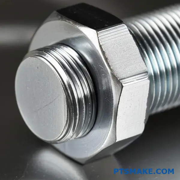
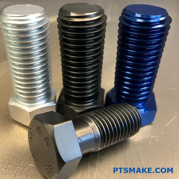
Inoltre, influisce sul modo in cui gli utensili interagiscono con il dispositivo di fissaggio. Nel caso di un bullone esagonale, la dimensione tra le superfici è il diametro maggiore. Una tolleranza non precisa in questo caso si traduce in un montaggio approssimativo della chiave, che può arrotondare gli angoli e rendere impossibile una coppia adeguata.
Diametro minore: Il cuore della forza
Il diametro minore di un dado o di un foro filettato è il suo fondamento. Questa dimensione indica direttamente le dimensioni della punta utilizzata prima della maschiatura. Se il foro è troppo piccolo, il maschiatore si incastra e si rompe.
Se il foro è troppo grande, la filettatura risultante sarà poco profonda e debole. Ciò riduce notevolmente la resistenza del collegamento. Il materiale in corrispondenza del diametro minore deve essere sufficiente a gestire i carichi previsti. Un controllo insufficiente in questo punto può introdurre aree di elevata concentrazione delle sollecitazioni6che è una delle cause principali del cedimento dei bulloni.
| Errore di tolleranza | Problema funzionale risultante |
|---|---|
| Diametro maggiore troppo grande | Le parti non si assemblano. |
| Diametro maggiore troppo piccolo | Scarsa presa dell'utensile, rischio di scivolamento. |
| Diametro minore troppo piccolo | Rottura del rubinetto durante la produzione. |
| Diametro minore troppo grande | Fili deboli che si spogliano facilmente. |
La tolleranza sul diametro maggiore controlla l'accoppiamento esterno, prevenendo le interferenze di assemblaggio e garantendo una presa sicura dell'utensile. La tolleranza sul diametro minore è fondamentale per le filettature interne, in quanto determina la dimensione della punta del rubinetto e salvaguarda la resistenza del nucleo del pezzo contro i cedimenti.
Perché la variazione zero dei fili è praticamente impossibile?
Dal punto di vista della fisica, la perfezione è un'illusione. Ottenere una variazione zero nei filetti non è solo difficile, è impossibile. Ogni fase di produzione introduce piccoli errori inevitabili.
Queste variazioni derivano da limiti fisici fondamentali. Dobbiamo tenere conto della macchina, dell'utensile, del materiale e anche delle variazioni di temperatura. La comprensione di questo aspetto aiuta a stabilire obiettivi realistici per la tolleranza della filettatura.
Ecco un rapido confronto tra l'obiettivo ideale e la realtà fisica con cui lavoriamo nella produzione di precisione.
| Aspetto | L'ideale (variazione zero) | La realtà |
|---|---|---|
| Processo | Perfettamente stabile e ripetibile | Micro-vibrazioni e deviazioni |
| Utensili | Dimensioni immutabili | Si consuma ad ogni utilizzo |
| Materiale | Completamente uniforme | Contiene microimpurità |
| Ambiente | Temperatura costante | Il calore provoca l'espansione |
Inseguire un filo "perfetto" inesistente non è solo poco pratico, ma anche incredibilmente costoso.
Le inflessibili leggi della fisica
Vediamo perché queste variazioni sono una parte fondamentale del mondo produttivo. Non si tratta di mancanza di competenze o di tecnologia, ma di fisica.
Limitazioni dei processi di produzione
Nessuna macchina è infinitamente rigida. Anche le macchine CNC più avanzate presentano vibrazioni e deflessioni microscopiche durante il funzionamento. Questi piccoli movimenti, quasi incommensurabili, si trasferiscono direttamente al pezzo da lavorare. Creano minime deviazioni dalla forma perfetta del filetto. Il materiale comportamento anisotropo7 significa anche che reagisce in modo diverso alle forze di taglio a seconda dell'orientamento della grana.
L'inevitabile usura degli utensili
Un utensile da taglio è più affilato solo prima del primo taglio. Ad ogni taglio effettuato, il tagliente si erode leggermente. L'usura è graduale ma inesorabile. Man mano che l'utensile si consuma, le dimensioni del filo che produce cambiano.
Ecco come l'usura degli utensili può influire su un lotto di pezzi:
| Numero di parte | Condizione dello strumento | Diametro del passo risultante |
|---|---|---|
| Parte #1 | Nuovo strumento | In linea con l'obiettivo |
| Parte #500 | Usura minore | Leggermente più grande |
| Parte #1000 | Usura moderata | Superamento del limite di tolleranza superiore |
Noi di PTSMAKE gestiamo questo aspetto attraverso un rigoroso monitoraggio della durata degli utensili e protocolli di sostituzione per mantenere costante la tolleranza della filettatura.
La natura dei materiali
Le materie prime non sono mai perfettamente uniformi. Contengono microscopiche incongruenze, variazioni di durezza e tensioni interne. Quando un utensile incide il materiale, queste imperfezioni lo fanno reagire in modi leggermente imprevedibili.
L'impatto nascosto dell'espansione termica
L'attrito del taglio genera un notevole calore. Questo calore provoca una dilatazione sia dell'utensile che del pezzo. Un pezzo misurato a caldo avrà dimensioni diverse rispetto a quando si raffredda. Per ottenere un'elevata precisione è necessario controllare e compensare questi effetti termici.
La ricerca della variazione zero si scontra con le leggi fondamentali della fisica. L'usura degli utensili, le incongruenze dei materiali, le vibrazioni della macchina e l'espansione termica sono tutte realtà intrinseche. Riconoscere questi limiti è il primo passo per ottenere una precisione realistica e ripetibile.
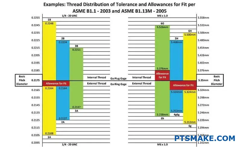
Confrontare i sistemi di tolleranza metrici ISO e unificati (UN/UNF).
La comprensione delle denominazioni delle filettature è fondamentale. I sistemi metrici ISO e unificati (UN/UNF) appaiono diversi sulla carta. Questo perché hanno strutture di designazione uniche.
Ad esempio, un'indicazione metrica comune è M8 x 1,25-6H. Per Unified, si potrebbe vedere 5/16-18 UNC-2B.
La designazione in sintesi
I codici raccontano una storia. I codici "6H" e "2B" definiscono il tolleranza della filettatura. Non sono intercambiabili. Riflettono filosofie di sistema completamente diverse.
| Sistema | Esempio di filettatura esterna | Esempio di filettatura interna |
|---|---|---|
| ISO Metrico | 6g | 6H |
| Unificato (ONU/UNF) | 2A | 2B |
Queste differenze hanno un impatto diretto sul montaggio e sul funzionamento dei pezzi. La scelta di quello giusto è fondamentale per qualsiasi progetto.
La filosofia alla base dei codici
Il sistema ISO è altamente strutturato. Utilizza un numero per il grado di tolleranza. Utilizza anche una lettera per la posizione. In questo modo si crea una matrice dettagliata dei possibili accoppiamenti.
Il sistema ONU/UNF è più basato sulle classi. Raggruppa gli accoppiamenti in ampie categorie. Le classi 1, 2 e 3 definiscono rispettivamente gli accoppiamenti larghi, standard e stretti. La classe 2 è la più comune per le applicazioni generali.
Implicazioni pratiche per i progettisti
I progettisti che lavorano a livello mondiale devono conoscere entrambi i sistemi. Un progettista americano che specifica un attacco di Classe 2B ha bisogno di un equivalente ISO. Di solito, 6H è la corrispondenza più vicina per una filettatura interna.
Ma non sono identici. Nei progetti passati di PTSMAKE, abbiamo visto che le discrepanze causano problemi di assemblaggio. Queste sottili differenze nella zona di tolleranza sono importanti. Il sistema ISO fornisce un controllo più granulare grazie all'uso di deviazioni fondamentali8.
Ecco un confronto generale delle applicazioni di adattamento:
| Classe Fit | Sistema | Applicazione tipica |
|---|---|---|
| Vestibilità ampia | 1A/1B (UNF), 7H/7g (ISO) | Facile da montare, consente l'ingresso di detriti |
| Misura standard | 2A/2B (UNF), 6H/6g (ISO) | Uso commerciale generico |
| Vestibilità stretta | 3A/3B (UNF), 4H/5g (ISO) | Alta precisione, gioco zero |
Questa traduzione è una parte fondamentale del nostro servizio DFM (Design for Manufacturability). Garantiamo il mantenimento dell'intento progettuale, indipendentemente dal sistema utilizzato nel disegno originale.
Etichetta dei sistemi ISO e ONU tolleranza della filettatura in modo diverso (ad esempio, 6H vs. 2B). Questi codici derivano da filosofie diverse: una sistematica, l'altra basata sulle classi. Per i progetti globali, la comprensione di queste distinzioni è fondamentale per evitare errori di assemblaggio e garantire il corretto funzionamento dei pezzi.
Conclusione: La scelta giusta per la vostra applicazione
La scelta tra le filettature di Classe 2A e 2B è semplice. Si tratta di una questione di adattamento e di funzionalità. Ricordate che la 2A è per le filettature esterne (bulloni, viti). Fornisce il gioco.
Questa piccola tolleranza è perfetta per rivestimenti o placcature. La classe 2B è per le filettature interne (dadi, fori filettati). Offre un accoppiamento standard senza spazi aggiuntivi.
Guida di riferimento rapido
Questa tabella semplifica il processo decisionale. Utilizzatela come verifica rapida dei vostri progetti.
| Classe | Tipo di filo | Caratteristiche principali | Caso d'uso comune |
|---|---|---|---|
| 2A | Esterno | Indennità (liquidazione) | Viti placcate o rivestite |
| 2B | Interno | Nessuna indennità | Dadi standard, fori filettati |
Questa distinzione è fondamentale per l'assemblaggio dei pezzi.
In ultima analisi, la scelta influisce sull'intero processo di produzione. Una semplice notazione su un disegno determina il nostro approccio alla produzione e all'ispezione. Nei progetti passati di PTSMAKE, abbiamo visto come la mancata considerazione di questo dettaglio possa causare notevoli problemi di assemblaggio lungo la linea.
Oltre le basi: Impatto della produzione
La tolleranza di filettatura specificata influisce direttamente sulla selezione degli utensili e sul controllo della qualità. Ad esempio, un rivestimento più spesso richiede un calcolo accurato per garantire che la filettatura finale 2A si accoppi correttamente con la sua controparte 2B. Non si tratta solo di numeri, ma di risultati pratici.
Per questo è fondamentale una comunicazione chiara con il partner di produzione. Aiutiamo i clienti a considerare i fattori che vanno oltre il progetto iniziale. Tra questi, la scelta dei materiali e le fasi di post-lavorazione. La nostra esperienza dimostra che una corretta calibrazione del calibro9 non è negoziabile per ottenere risultati costanti.
Fattori che influenzano la decisione
Considerate questi punti quando specificate la vostra classe di filettatura. Ognuno di essi ha un ruolo nelle prestazioni e nel costo della parte finale.
| Fattore | Considerazione per la scelta 2A/2B |
|---|---|
| Post-elaborazione | Il pezzo sarà placcato, anodizzato o rivestito? Se sì, è necessario il 2A. |
| Montaggio | È sufficiente una calzata standard e affidabile? 2B è la scelta ideale. |
| Ambiente | La corrosione sarà un fattore? I rivestimenti protetti da 2A aiutano. |
| Costo | I filetti di classe 2 offrono un ottimo equilibrio tra prestazioni e producibilità. |
Discutere questi fattori in anticipo evita costose rilavorazioni e ritardi.
La scelta corretta tra le filettature di Classe 2A e 2B garantisce un accoppiamento corretto, soprattutto dopo la post-lavorazione. È un dettaglio fondamentale per il successo dell'assemblaggio e del funzionamento. Una comunicazione chiara con il produttore, come noi di PTSMAKE, è essenziale per ottenere la giusta tolleranza di filettatura.
In che modo le classi di tolleranza creano diversi accoppiamenti meccanici?
Gli accoppiamenti meccanici sono il cuore dell'ingegneria di precisione. Definiscono il modo in cui due parti si assemblano e funzionano insieme. Tutto dipende dal rapporto tra il foro e l'albero.
Esistono tre tipi principali di fit. Ognuno di essi è creato da specifiche combinazioni di classi di tolleranza. Queste determinano il comportamento dell'assieme finale.
Spazio libero Adatto
In questo caso, l'albero è sempre più piccolo del foro. Questo garantisce lo spazio tra le parti. Possono muoversi o ruotare liberamente. Una combinazione H7/g6 è un esempio classico.
Adattamenti di transizione
Questa è la via di mezzo. Le tolleranze del foro e dell'albero si sovrappongono. Il montaggio finale potrebbe presentare un piccolo gioco o una leggera interferenza. Un H7/k6 è una scelta comune in questo caso.
Interferenze
In questo caso, l'albero è sempre più grande del foro. È necessaria una forza per assemblare le parti. In questo modo si crea un collegamento forte e fisso. H7/p6 è un tipico accoppiamento per interferenza.
Approfondimento sulle applicazioni Fit
La scelta dell'accoppiamento giusto è fondamentale. Ha un impatto diretto su prestazioni, assemblaggio e costi. Nei nostri progetti all'PTSMAKE, questa decisione è una parte fondamentale del processo di revisione del progetto.
Uso pratico degli accoppiamenti liberi (ad es., H7/g6)
Pensate a un semplice cuscinetto su un albero rotante che non sopporta un carico pesante. È necessario uno spazio per la lubrificazione e la libera rotazione. L'accoppiamento garantisce che l'albero possa ruotare senza legarsi all'interno della pista interna del cuscinetto. I vantaggi sono anche la facilità di montaggio e smontaggio.
Quando utilizzare i fit di transizione (ad es., H7/k6)
Gli attacchi di transizione servono per una collocazione precisa. Offrono un montaggio aderente senza bisogno di una forza significativa. Si pensi agli ingranaggi o alle pulegge su un albero. Devono essere posizionati con precisione, ma possono anche essere rimossi per la manutenzione. Questo accoppiamento offre questo equilibrio. Principi simili si applicano a tolleranza della filettatura10 per garantire il corretto posizionamento degli elementi di fissaggio.
Il potere dell'interferenza Si adatta (ad esempio, H7/p6)
Gli accoppiamenti per interferenza creano assemblaggi robusti e permanenti. Trasmettono coppie o sopportano carichi pesanti senza chiavi o perni. Un esempio comune è la pressione di un perno di acciaio indurito in un alloggiamento più morbido. Le parti si deformano elasticamente, creando un'enorme pressione e attrito.
| Tipo di vestibilità | Esempio di combinazione | Applicazione tipica | Nota di montaggio |
|---|---|---|---|
| Liquidazione | H7/g6 | Albero in un cuscinetto a sfere | Le parti scorrono insieme |
| La transizione | H7/k6 | Perni di localizzazione, Spigots | Necessità di una forza leggera |
| Interferenza | H7/p6 | Cuscinetto in un alloggiamento | Necessario il montaggio a pressione |
La comprensione di questi tre tipi di accoppiamento è fondamentale. Selezionando le classi di tolleranza corrette per un foro e un albero, è possibile controllare con precisione se i pezzi si muoveranno liberamente, si posizioneranno con precisione o si bloccheranno in modo permanente.
In che modo la placcatura o il rivestimento influiscono sulla tolleranza della filettatura?
La placcatura o il rivestimento aggiungono un sottile strato di materiale. Questo strato aumenta le dimensioni finali del pezzo. Per le filettature, questo è un aspetto critico.
Questo materiale aggiunto consuma lo spazio previsto. Questo spazio, o margine, assicura che i pezzi si incastrino senza problemi.
Senza un'adeguata pianificazione, le filettature potrebbero non assemblarsi. L'accoppiamento diventa troppo stretto, causando interferenze. Ciò influisce direttamente sulla tolleranza della filettatura.
L'impatto dello spessore aggiunto
Anche pochi micron di placcatura possono essere importanti. La tabella seguente mostra come i diversi rivestimenti possono influire sull'accoppiamento.
| Tipo di rivestimento | Spessore tipico (μm) | Rischio di interferenza |
|---|---|---|
| Zincatura | 5-15 | Medio |
| Nichel elettrolitico | 10-25 | Alto |
| Anodizzazione (tipo II) | 5-18 | Medio |
Per questo motivo è necessario tenere conto dello spessore del rivestimento fin dall'inizio.
Come gli standard risolvono il puzzle della placcatura
Quindi, come possiamo evitare questa interferenza? Non possiamo ignorare lo spessore del rivestimento.
Gli enti normativi come l'ISO offrono una soluzione intelligente. Specificano diverse classi di tolleranza della filettatura per i pezzi da rivestire.
Questo approccio modifica la posizione iniziale del filo. In questo modo si crea spazio per il futuro rivestimento.
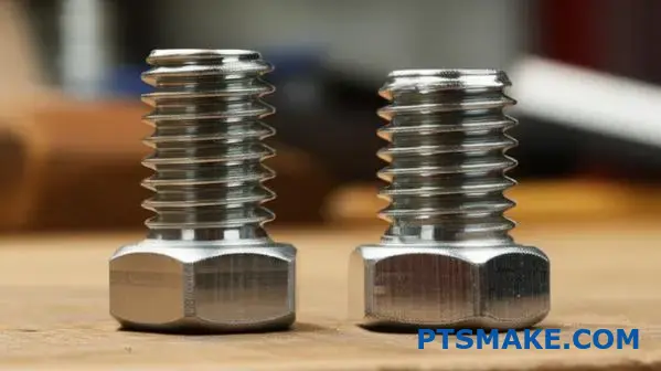
Per le filettature esterne non rivestite, è comune la posizione "h". Ha una tolleranza pari a zero. Ciò significa che la dimensione massima della filettatura è quella di base.
Per i filetti destinati alla placcatura, invece, si utilizza una posizione "g". In questo modo si crea una fessura incorporata prima ancora di applicare il rivestimento.
Questo divario, definito dal deviazione fondamentale11è progettato per adattarsi allo spessore del rivestimento.
Dimensioni prima della placcatura e dopo la placcatura
L'obiettivo è semplice. Dopo la placcatura, la filettatura di posizione "g" deve essere adatta come una filettatura di posizione "h" standard.
| Posizione del filo | Indennità | Uso previsto | Montaggio finale (dopo la placcatura) |
|---|---|---|---|
| h (ad esempio, 6h) | Zero | Non rivestito | N/D |
| g (ad esempio, 6g) | Positivo | Da placcare/rivestire | Simile a 6h |
Applicazione pratica all'PTSMAKE
Noi di PTSMAKE discutiamo sempre delle finiture superficiali fin dalle prime fasi della progettazione. Ci assicuriamo che venga specificata la corretta tolleranza della filettatura di preplaccatura.
Questa fase proattiva evita costose rilavorazioni. Inoltre, evita ritardi dovuti a parti che non si assemblano correttamente.
I rivestimenti aggiungono spessore, il che può rovinare la tenuta della filettatura. Per risolvere questo problema, gli standard utilizzano speciali classi di tolleranza pre-rivestimento. Queste classi, come la "g" per le filettature esterne, creano uno scarto iniziale per fare spazio al rivestimento, garantendo un assemblaggio corretto.
Qual è il sistema alla base degli indicatori Go/No-Go?
I calibri Go/No-Go sono più che semplici strumenti di ispezione. Sono la rappresentazione fisica dei limiti di tolleranza di un componente. Sono una prova fisica diretta dei disegni di progetto.
Il lato "Vai" conferma la dimensione minima accettabile dell'elemento. Deve essere adatta. Al contrario, il lato "No-Go" rappresenta la dimensione massima accettabile. Non deve adattarsi.
Questo semplice sistema binario elimina le congetture. Fornisce un chiaro verdetto di accettazione o meno, assicurando che ogni pezzo aderisca alla tolleranza di filettatura richiesta.
L'eleganza del sistema Go/No-Go risiede nella traduzione diretta di numeri astratti in un controllo fisico. La tolleranza della filettatura di un pezzo è definita da limiti superiori e inferiori; i calibri vengono lavorati esattamente in base a queste condizioni limite.
L'indicatore di marcia: Verifica dell'assemblaggio
Il calibro "Go" è prodotto in base alla condizione massima del materiale della filettatura (MMC). Per una filettatura interna, come quella di un dado, questo corrisponde al diametro del passo più piccolo consentito.
Se il calibro "Go" si infila senza problemi, garantisce che il pezzo si assemblerà con il suo compagno corrispondente. Conferma che il pezzo non è troppo piccolo.
Il calibro "No-Go": Garantire il corretto adattamento
Il calibro "No-Go" controlla la condizione di minimo materiale (LMC). Per una filettatura interna, questo è il diametro massimo consentito del passo. Assicura che la filettatura non sia troppo allentata.
Questo calibro non deve essere in grado di entrare nel pezzo. Questo controllo critico garantisce un impegno sufficiente della filettatura, fondamentale per una connessione forte e sicura. La progettazione e l'utilizzo di questi calibri seguono un concetto fondamentale noto come Principio di Taylor12.
Nei processi di controllo della qualità di PTSMAKE, questa è una fase fondamentale. Garantisce che i pezzi lavorati CNC che forniamo soddisfino la precisa tolleranza di filettatura richiesta dai nostri clienti.
| Tipo di calibro | Controlla questa condizione | Scopo | Risultato per una buona parte |
|---|---|---|---|
| Misuratore di velocità | Condizione massima del materiale (MMC) | Assicura l'assemblaggio delle parti | Deve essere adatto |
| Indicatore di non ritorno | Condizione di minimo materiale (LMC) | Assicura che le parti non siano troppo allentate | Non deve essere adatto |
I calibri Go/No-Go rappresentano fisicamente la tolleranza della filettatura di un pezzo. Il calibro "Go" conferma la condizione massima del materiale per l'assemblaggio, mentre il calibro "No-Go" controlla la condizione minima del materiale per garantire un accoppiamento sicuro ed evitare guasti dovuti all'allentamento.
In che modo la scelta del materiale influenza la selezione delle tolleranze?
La scelta del materiale non si limita alla resistenza e al peso. Le proprietà intrinseche di un materiale influenzano direttamente le tolleranze che si possono ottenere in modo pratico ed economico.
Duttilità e lavorabilità
I materiali altamente duttili possono deformarsi sotto la pressione di taglio. Ciò rende più complesso il raggiungimento di tolleranze strettissime e può aumentare i tempi di lavorazione.
Problemi di espansione termica
I materiali si espandono e si contraggono con le variazioni di temperatura. L'accoppiamento di parti di materiali diversi, come l'alluminio e l'acciaio, richiede un'attenta riflessione.
| Materiale | Coefficiente di espansione termica (ppm/°C) |
|---|---|
| Alluminio | ~23 |
| Acciaio | ~12 |
Questo disallineamento significa che le tolleranze devono tenere conto dell'ambiente operativo previsto per evitare vincoli o guasti.
Uno sguardo più approfondito ai comportamenti dei materiali
Capire come si comporta un materiale durante la lavorazione e nell'applicazione finale è fondamentale per stabilire tolleranze realistiche. In questo modo si evita un'eccessiva ingegnerizzazione e costosi fallimenti.
Effetto della duttilità sulla precisione
I materiali duttili, come alcune leghe di alluminio, possono creare trucioli lunghi e filiformi durante la lavorazione. Questo può avvolgere gli utensili e rovinare la superficie del pezzo. Noi di PTSMAKE controlliamo attentamente gli avanzamenti e le velocità per attenuare questo fenomeno, ma è un fattore chiave quando si definiscono tolleranze molto strette.
La sfida di Galling
Materiali come l'acciaio inossidabile sono soggetti a galla13in cui le superfici si saldano essenzialmente sotto pressione. Si tratta di un problema critico per gli elementi di fissaggio. Una tolleranza di filettatura leggermente inferiore può fornire il gioco necessario per evitare il grippaggio, assicurando che le parti possano essere assemblate e smontate in modo affidabile.
Gestione termica degli assemblaggi
In progetti passati, abbiamo assistito al fallimento di gruppi perché l'espansione termica è stata ignorata. Un albero in acciaio a tenuta stagna in un alloggiamento in alluminio a temperatura ambiente potrebbe gripparsi completamente alla temperatura di esercizio più elevata. Le tolleranze devono essere progettate per l'intero intervallo di temperature funzionali.
| Proprietà | Esempio di materiale | Raccomandazione di tolleranza |
|---|---|---|
| Alta duttilità | Rame | Una tolleranza minore può essere più efficace dal punto di vista dei costi. |
| Tendenza all'accanimento | Acciaio inox | Prendere in considerazione specifiche più basse, soprattutto per quanto riguarda la tolleranza della filettatura. |
| Elevata espansione termica | Plastica, alluminio | Calcolare le tolleranze per l'intera temperatura di esercizio. |
| Fragilità | Acciaio temprato, ceramica | Sono possibili tolleranze più strette, ma aumenta il rischio di fratture. |
Le proprietà dei materiali, come la duttilità, l'espansione termica e la galla, non sono semplici dati, ma vincoli progettuali. Il successo della selezione delle tolleranze dipende dalla comprensione di questi comportamenti per garantire che un pezzo funzioni correttamente e in modo affidabile durante il suo ciclo di vita, evitando guasti evitabili.
Illustrare il processo di selezione della giusta tolleranza di filettatura.
La scelta della giusta tolleranza del filo sembra complessa. Ma è un processo logico. Si tratta di far coincidere il lavoro del pezzo con il modo in cui viene prodotto. Un approccio sistematico evita l'eccessiva ingegnerizzazione e controlla i costi.
Vi forniremo una guida chiara, passo dopo passo. Questo vi aiuterà a prendere sempre la decisione giusta. Per fare chiarezza, suddividiamo il tutto in fasi semplici e gestibili.
Iniziare con i bisogni funzionali
Innanzitutto, bisogna definire cosa deve fare la filettatura. La priorità assoluta è la facilità di montaggio? Oppure deve resistere a vibrazioni costanti? Ogni funzione indica un diverso livello di tolleranza.
| Requisiti funzionali | Obiettivo di tolleranza tipico |
|---|---|
| Montaggio facile e veloce | Tolleranza minore (ad esempio, 6g/6H) |
| Resistenza alle vibrazioni | Tolleranza più stretta (ad esempio, 4g6g/4H5H) |
| Fissaggio ad alta resistenza | Tolleranza da media a stretta |
| Applicazioni di sigillatura | Tolleranza più stretta con il sigillante |
Un accoppiamento più lasco è ottimo per una produzione rapida. Un accoppiamento più stretto garantisce l'affidabilità sotto sforzo.
Poi dobbiamo considerare il processo di produzione e il suo impatto. Il metodo utilizzato per creare il filo influenza direttamente la precisione ottenibile e il costo finale. Si tratta di un bilanciamento critico.
Considerare la produzione e i costi
Il processo di produzione scelto stabilisce limiti realistici. La lavorazione CNC, in cui siamo specializzati alla PTSMAKE, offre un'elevata precisione per tolleranze ristrette. Tuttavia, metodi come la rullatura o la formatura dei filetti sono diversi.
Le tolleranze più strette richiedono una lavorazione più precisa. Ciò significa più tempo macchina, utensili specializzati e ispezioni rigorose. Tutto questo fa lievitare i costi. È importante chiedersi se il costo aggiuntivo fornisce un reale vantaggio in termini di prestazioni. Nei nostri progetti, abbiamo visto che spesso una tolleranza leggermente più bassa ma costante è migliore di una tolleranza inutilmente stretta.
Fattore ambientale
Dove verrà utilizzato il pezzo? Le alte temperature possono causare l'espansione dei materiali. Gli ambienti corrosivi possono influire sulle superfici delle filettature. Questi fattori possono cambiare il modo in cui le filettature si adattano e funzionano nel tempo. Anche la scelta del materiale è fondamentale.
Selezione della classe di tolleranza finale
Con tutte queste informazioni, è ora possibile selezionare una classe di tolleranza specifica. Questa decisione deve bilanciare funzione, producibilità e costo. Non si tratta solo di scegliere l'opzione più stretta. Si tratta di scegliere quella più intelligente per l'applicazione. Corretto Ripetibilità e riproducibilità del calibro14 garantisce che qualsiasi classe selezionata possa essere verificata in modo affidabile.
| Fattore | Tolleranza più bassa | Tolleranza più stretta |
|---|---|---|
| Velocità di montaggio | Più veloce | Più lento |
| Blocco delle vibrazioni | Più basso | Più alto |
| Costo di produzione | Più basso | Più alto |
| Difficoltà di misurazione | Più facile | Più complesso |
Questo processo strutturato consente di passare dalle esigenze generali a una selezione specifica e giustificabile delle tolleranze di filettatura.
Un processo decisionale chiaro è fondamentale. Valutando la funzione, la produzione, il costo e l'ambiente, si può scegliere con sicurezza la tolleranza di filettatura ottimale, in grado di bilanciare i requisiti di prestazione con il budget, assicurando un risultato positivo per il progetto.
Come si selezionano i misuratori di ispezione corretti?
L'interpretazione di un disegno è il primo passo. Detta l'intero piano di ispezione. È un linguaggio preciso.
Questo processo assicura che ogni pezzo sia conforme alle specifiche. Indica esattamente quali calibri estrarre dalla culla degli utensili.
Di seguito è riportata una guida rapida. Mostra come una caratteristica di un disegno si traduce in tipi di calibro specifici.
| Caratteristica del disegno | Tipo di calibro richiesto |
|---|---|
| Filettatura M8x1.25-6H | Misuratore di spine per filettatura Go/No-Go |
| Ø10,00 Foro H7 | Misuratore a spina liscia Go/No-Go |
| Ø25,00 g6 Albero | Calibro ad anello liscio Go/No-Go |
Questo approccio sistematico elimina le congetture. Costruisce una base per un controllo di qualità costante.
Una procedura pratica per la selezione del calibro
Noi di PTSMAKE seguiamo una procedura chiara. In questo modo ci assicuriamo di selezionare gli strumenti giusti per ogni singola caratteristica. Si inizia con il disegno tecnico.
Fase 1: decodifica della chiamata
In primo luogo, analizziamo il disegno in dettaglio. Identifichiamo la dimensione nominale, il passo e la tolleranza critica della filettatura. Queste informazioni costituiscono la base per la selezione del calibro. Ogni dettaglio è importante per ottenere un accoppiamento perfetto.
Fase 2: Scelta dei calibri di lavoro
In base alle indicazioni, selezioniamo i calibri di lavoro. Per una filettatura interna, utilizziamo un calibro per tappi Go/No-Go. Per una filettatura esterna, si tratta di un calibro ad anello.
| Parte Caratteristica | Calibro di lavoro | Scopo |
|---|---|---|
| Filettatura interna | Misuratore di spine per filettatura | Controlla il diametro minimo e massimo del passo |
| Filettatura esterna | Calibro per anelli filettati | Verifica il profilo e le dimensioni della filettatura |
| Foro semplice | Calibro a spina liscia | Assicura che il foro rientri nella tolleranza del diametro |
| Albero/perno | Calibro dell'anello liscio | Conferma che l'albero rientra nella tolleranza del diametro |
Fase 3: Non dimenticare la verifica del calibro
Per i calibri ad anello per filettatura, utilizziamo sempre i master controllare le spine15. Questi tappi verificano che il calibro ad anello sia preciso e non si sia usurato. Si tratta di una fase critica di garanzia della qualità.
Fase 4: sapere quando i misuratori non sono sufficienti
A volte i calibri non sono sufficienti. Nel caso di pezzi con tolleranze molto strette, profili complessi o funzioni di sicurezza critiche, si ricorre a strumenti avanzati come CMM, comparatori ottici o sistemi di visione per un'analisi più dettagliata. Utilizziamo strumenti avanzati come CMM, comparatori ottici o sistemi di visione per un'analisi più dettagliata.
Questa decisione si basa sul rischio. Se un guasto è catastrofico, utilizziamo il metodo di misurazione più preciso disponibile.
La scelta dei giusti calibri di ispezione è un processo disciplinato. Si inizia leggendo attentamente il disegno e scegliendo sistematicamente i calibri di lavoro e gli strumenti di verifica. Conoscere i limiti dei calibri e sapere quando utilizzare una CMM avanzata o un'ispezione ottica è fondamentale per garantire la qualità totale.
In che modo il restringimento di una tolleranza influisce sui costi di produzione?
La relazione tra grado di tolleranza e costo non è lineare, ma esponenziale. Passare da una tolleranza grossolana a una fine aumenta drasticamente i costi.
Non si tratta di un piccolo aumento di prezzo. Si tratta di un cambiamento fondamentale nel processo di produzione.
La curva grado di tolleranza-costo
Considerate le classi di tolleranza del filo comune. Passare da un 8g standard a un 4g fine richiede un approccio e un budget completamente diversi.
Ecco una ripartizione semplificata:
| Caratteristica | Tolleranza grossolana (ad es. 8 g) | Tolleranza fine (ad esempio, 4 g) |
|---|---|---|
| Tipo di macchina | CNC standard | CNC ad alta precisione |
| Velocità di produzione | Più veloce | Più lento |
| Impatto sui costi | Linea di base | Significativamente più alto |
Ogni passo verso una tolleranza più stretta aggiunge complessità e, quindi, costi.

Il passaggio a un grado di tolleranza più fine ha un impatto su ogni fase della produzione. Noi di PTSMAKE guidiamo i nostri partner attraverso queste implicazioni per trovare un equilibrio tra precisione e costi.
Fabbisogno di macchinari e utensili
Una macchina CNC standard potrebbe essere perfetta per una filettatura da 8g. Ma per una tolleranza di filettatura di 4 g, spesso è necessaria una macchina di livello superiore. Queste macchine offrono maggiore stabilità e precisione, ma hanno un costo superiore.
Un altro fattore è rappresentato dagli utensili. Per mantenere una tolleranza stretta, gli utensili devono essere cambiati più frequentemente. Si consumano più rapidamente e anche un'usura minima può portare un pezzo fuori specifica. Ciò significa maggiori spese per nuovi utensili e maggiori tempi di fermo macchina per le sostituzioni.
Impatto della produzione e del tasso di scarto
La precisione richiede pazienza. Le macchine devono funzionare a velocità e avanzamenti inferiori per ottenere finiture più fini e mantenere tolleranze ristrette. Questo aumenta direttamente il tempo di ciclo per pezzo.
Anche il margine di errore si riduce drasticamente. Una minima vibrazione o uno sbalzo di temperatura possono portare allo scarto di un pezzo. In base ai dati dei nostri progetti, il passaggio a una tolleranza molto fine può aumentare i tassi di scarto da meno di 2% a oltre 5% o anche più. Ogni pezzo scartato è uno spreco di materiale, tempo macchina e manodopera. Anche il processo di ispezione stesso diventa più intensivo, e spesso richiede un'analisi avanzata. Metrologia16 strumenti.
| Driver di costo | Tolleranza grossolana Impatto | Tolleranza fine Impatto |
|---|---|---|
| Tempo di lavorazione | Basso | Alta (velocità ridotta) |
| Costo degli utensili | Standard | Alto (cambi frequenti) |
| Costo dell'ispezione | Controlli di base | Attrezzatura avanzata necessaria |
| Tasso di scarto | In genere < 2% | Spesso > 5% |
L'inasprimento di un grado di tolleranza aumenta significativamente i costi. Ciò è dovuto alla necessità di macchinari migliori, cambi di utensili più frequenti, ritmi di produzione più lenti e tassi di scarto più elevati. Si tratta di un compromesso tra precisione e budget che richiede un'attenta considerazione.
Come creereste uno standard aziendale interno?
La creazione di una guida specifica per l'azienda è essenziale. Elimina le congetture per il team di progettazione. In questo modo si riducono gli errori e si snellisce la produzione.
Un semplice modello può fare una grande differenza. Standardizza l'approccio alle tolleranze fin dall'inizio.
Un punto di partenza per la vostra guida
Questa guida dovrebbe collegare i tipi di applicazione alle classi di tolleranza predefinite. In questo modo si garantisce che tutti i membri del team siano sulla stessa lunghezza d'onda.
Ecco una struttura di base su cui basarsi:
| Categoria di applicazione | Classe di tolleranza consigliata | Esempio |
|---|---|---|
| Componenti non critici | Sciolto (ad esempio, ISO 2768-c) | Coperture esterne, pannelli cosmetici |
| Forma e funzionalità generali | Medio (ad esempio, ISO 2768-m) | Staffe, supporti strutturali |
| Parti di precisione e di accoppiamento | Fine (ad esempio, ISO 2768-f) | Perni di posizionamento, componenti a pressione |
Questa struttura fornisce una guida chiara e immediata ai progettisti.
Dettaglio delle categorie di applicazioni
Il vero valore deriva dall'ampliamento di queste categorie. È necessario definire ciò che rientra in ciascuna classe. In questo modo si evita l'ambiguità.
Componenti non critici
Questi componenti di solito non hanno funzioni portanti o di interfacciamento preciso. Si pensi a coperture decorative o a semplici involucri. L'utilizzo di tolleranze meno rigide in questo caso può ridurre significativamente i costi di produzione senza influire sulla funzionalità del prodotto finale.
Parti strutturali e funzionali
Si tratta di una categoria ampia. Comprende tutto, dalle staffe di montaggio ai telai di supporto interni. La coerenza è fondamentale. Per le parti imbullonate, la standardizzazione della tolleranza della filettatura è particolarmente importante per garantire un assemblaggio e prestazioni affidabili.
Caratteristiche di localizzazione di precisione
Queste sono le aree più critiche. Determinano l'allineamento e l'assemblaggio dell'intero prodotto. Caratteristiche come i fori dei perni o le sedi dei cuscinetti richiedono uno stretto controllo. Questo assicura una perfetta intercambiabilità17 tra le parti, fondamentale sia per l'assemblaggio iniziale che per le riparazioni successive.
Noi di PTSMAKE forniamo spesso consulenza ai clienti su queste classificazioni. La nostra esperienza nella lavorazione contribuisce a colmare il divario tra l'intento progettuale e la realtà produttiva.
| Esempio di funzione | Categoria di applicazione | Grado ISO suggerito | Motivazione |
|---|---|---|---|
| Alloggiamento esterno | Non critico | IT12 - IT14 | L'estetica è fondamentale, ma la vestibilità non è precisa. |
| Schema dei fori di montaggio | Strutturale e funzionale | IT9 - IT11 | Assicura l'allineamento con i componenti di accoppiamento. |
| Foro del cuscinetto | Localizzazione di precisione | IT6 - IT7 | Richiede un adattamento specifico per il corretto funzionamento. |
| Foro per il perno di fissaggio | Localizzazione di precisione | IT5 - IT6 | È fondamentale per l'allineamento accurato degli assiemi. |
Una guida di tolleranza ben definita è uno strumento potente. Standardizza le pratiche di progettazione, riduce gli errori e aiuta a controllare i costi di produzione applicando la precisione solo dove è veramente necessaria. Questo porta a prodotti più coerenti e affidabili.
Analizzare il guasto di un prodotto dovuto a un'errata tolleranza della filettatura.
Un guasto del prodotto può essere costoso. Esaminiamo un caso: una filettatura di alluminio spanata in un alloggiamento di acciaio. Questo problema sembra piccolo, ma può bloccare un'intera catena di montaggio.
La causa principale raramente è un singolo errore. Spesso si tratta di una combinazione di fattori. La scarsa tolleranza della filettatura è uno dei principali. Ma anche la scelta del materiale e la forza di assemblaggio giocano un ruolo fondamentale.
Analizziamo i fattori di fallimento.
| Fattore | Descrizione | Impatto |
|---|---|---|
| Tolleranza | Incompatibilità tra le filettature | Alto |
| I materiali | Disparità di durezza/resistenza | Alto |
| Coppia | Forza eccessiva durante il montaggio | Alto |
L'analisi mostrerà come questi elementi si siano combinati per causare un guasto critico.
Uno sguardo più approfondito: Analisi delle cause profonde
In un progetto passato, un cliente ha dovuto affrontare esattamente questo problema. Un componente in alluminio si è ripetutamente guastato quando è stato avvitato a un telaio in acciaio. La nostra indagine ha evidenziato tre cause interconnesse.
Il disallineamento materiale
In primo luogo, i materiali non erano partner ideali. L'alluminio è molto più morbido dell'acciaio. Quando si applica una forza, le filettature in alluminio più morbide sono le prime a deformarsi e a spanarsi. Si tratta di una considerazione fondamentale per la progettazione, spesso trascurata.
Tolleranza della filettatura errata
La tolleranza della filettatura specificata era troppo bassa. Ciò ha creato un impegno insufficiente della filettatura. Sotto carico, la forza si concentrava solo su alcune filettature. Questi pochi punti di contatto non erano in grado di gestire le sollecitazioni, con conseguente spanatura. L'interazione tra materiali dissimili è stata influenzata anche dalla Coefficiente di espansione termica18.
Coppia di montaggio eccessiva
Infine, le istruzioni di montaggio indicavano una coppia di serraggio adatta alle connessioni acciaio-acciaio. Questa coppia era di gran lunga troppo elevata per le morbide filettature in alluminio. Questa forza eccessiva è stata l'azione finale che ha causato il distacco completo delle filettature.
| Causa principale | Analisi | Soluzione |
|---|---|---|
| Scelta del materiale | L'alluminio è troppo morbido per l'alloggiamento in acciaio. | Utilizzare un inserto in acciaio (ad esempio, Helicoil) nella parte in alluminio. |
| Tolleranza della filettatura | La scarsa tolleranza ha portato a una cattiva distribuzione del carico. | Stringere la tolleranza per ottenere un migliore impegno della filettatura. |
| Coppia di montaggio | Le specifiche di coppia erano troppo elevate per l'alluminio. | Ricalcolare e specificare un valore di coppia inferiore. |
Questa analisi sistematica ha aiutato noi di PTSMAKE a fornire un percorso chiaro verso una soluzione affidabile per il nostro cliente.
Questo caso dimostra che il fallimento di un prodotto è una reazione a catena. Una tolleranza di filettatura errata, una scelta di materiale inadeguata e una coppia di montaggio sbagliata hanno creato la tempesta perfetta. Un singolo anello debole ha compromesso l'intero progetto.
Decostruire le scelte di filettatura in un assemblaggio aerospaziale.
Nel settore aerospaziale, ogni componente è importante. Esaminiamo un giunto imbullonato ad alte prestazioni. Le scelte qui non sono arbitrarie. Sono decisioni ingegneristiche deliberate.
Ci concentreremo su una combinazione specifica. Questa comprende la forma della filettatura UNJF, una classe di tolleranza ristretta e rivestimenti specializzati.
Questi elementi lavorano insieme. Garantiscono che il giunto soddisfi i requisiti estremi di sicurezza, peso e affidabilità a lungo termine. Un piccolo dettaglio può fare una grande differenza.
| Caratteristica | Bullone standard | Bullone aerospaziale |
|---|---|---|
| Forma del filo | ONU | UNJF (radice arrotondata) |
| Tolleranza | Classe 2A/2B | Classe 3A/3B |
| Materiale | Acciaio legato | Titanio / Inconel |
| Rivestimento | Zincatura | Argento / Lubrificante a film secco |
Il vantaggio della forma del filo UNJF
Perché scegliere i filetti UNJF? La "J" è fondamentale. Indica un raggio di radice controllato nella filettatura esterna. Questa radice arrotondata non è un dettaglio secondario. Riduce drasticamente le concentrazioni di stress nel punto più debole della filettatura.
Questo design migliora direttamente la durata a fatica dell'elemento di fissaggio. Nel settore aerospaziale, i componenti sono sottoposti a milioni di cicli di vibrazioni. Una radice affilata, come in una filettatura UN standard, creerebbe un punto di partenza per una cricca da fatica. Il design UNJF lo impedisce.
Tolleranze strette per una massima affidabilità
Successivamente, si consideri il Tolleranza della filettatura. I giunti aerospaziali utilizzano quasi sempre un accoppiamento di Classe 3A/3B. Si tratta di una tolleranza molto più stretta rispetto alle comuni classi 2A/2B. Un accoppiamento stretto garantisce una maggiore superficie di contatto tra le filettature del bullone e del dado.
Questo contatto migliorato distribuisce il carico in modo più uniforme. Impedisce lievi movimenti che potrebbero portare all'usura. Nel tempo, tali movimenti possono causare problemi come Corrosione da sfregamento19che compromette l'integrità del giunto. Per PTSMAKE, il raggiungimento di queste tolleranze precise è una parte fondamentale dei nostri servizi di lavorazione CNC per i clienti del settore aerospaziale.
| Classe di tolleranza | Descrizione della vestibilità | Applicazione tipica |
|---|---|---|
| 1A/1B | Vestibilità ampia | Montaggio rapido, condizioni di sporco |
| 2A/2B | Misura standard | La maggior parte dei prodotti commerciali |
| 3A/3B | Vestibilità stretta | Alta sollecitazione, alta affidabilità |
Il ruolo dei rivestimenti avanzati
Infine, i rivestimenti non sono solo estetici. Nel nostro esempio, una placcatura d'argento potrebbe essere utilizzata su un bullone in titanio. Questo serve a uno scopo fondamentale. Funge da lubrificante solido.
In questo modo si evita la formazione di galla durante l'accoppiamento con un dado. Inoltre, migliora la conduttività e protegge dalla corrosione. I rivestimenti sono un trattamento superficiale funzionale scelto per specifiche sfide ambientali e meccaniche.
Nei giunti aerospaziali ad alte prestazioni, ogni caratteristica è ottimizzata. La forma della filettatura UNJF, stretta Tolleranza della filettaturae rivestimenti avanzati sono essenziali. Vengono selezionati per massimizzare la durata a fatica, garantire l'affidabilità e mantenere un elevato rapporto resistenza/peso.
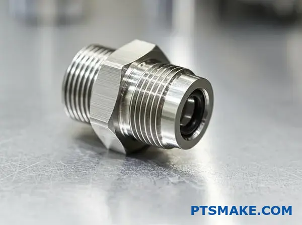
Progettare la connessione filettata di un raccordo idraulico ad alta pressione.
Per mettere insieme tutto questo è necessaria una strategia chiara. La progettazione di un raccordo ad alta pressione non si basa su una sola scelta. È una questione di come tre elementi chiave lavorano di concerto.
È necessario giustificare la forma della filettatura, il materiale e le specifiche di tolleranza. Queste decisioni garantiscono una tenuta a prova di perdite in condizioni estreme.
Il trio decisionale di base
Selezione della forma della filettatura
La scelta di questo punto pone le basi. Determina il meccanismo di tenuta principale.
| Caratteristica | NPTF (Dryseal) | O-ring SAE Boss |
|---|---|---|
| Metodo di sigillatura | Deformazione della filettatura | O-ring elastomerico |
| Resistenza alle vibrazioni | Fiera | Eccellente |
| Riutilizzabilità | Limitato | Alto |
Materiale e tolleranza
Questi due aspetti sono strettamente legati. Il materiale deve sopportare la pressione, mentre la tolleranza assicura che la guarnizione si innesti correttamente.
Giustificare il progetto per una tenuta robusta
Risolviamo un problema complesso. Immaginate un raccordo per un sistema idraulico mobile. Dovrà affrontare picchi di pressione elevati e vibrazioni costanti.
Scelta della forma della filettatura: O-ring Boss SAE
Per questa applicazione, sceglierei il raccordo O-ring SAE (ORB). A differenza delle filettature NPTF, che sigillano per deformazione della filettatura, l'ORB utilizza un O-ring. Questo garantisce una resistenza superiore alle perdite indotte dalle vibrazioni. È una soluzione più affidabile a lungo termine.
L'O-ring si basa su un controllo deformazione elastica20 per mantenere una tenuta positiva contro la superficie del raccordo. Ciò la rende molto più tollerante e riutilizzabile di una guarnizione metallo-metallo.
Selezione del materiale: Acciaio inox 316
La scelta del materiale è fondamentale. L'acciaio al carbonio, pur essendo comune, è soggetto alla corrosione, che può compromettere la superficie di tenuta.
| Materiale | Pressione nominale | Resistenza alla corrosione |
|---|---|---|
| Acciaio al carbonio | Alto | Fiera |
| Acciaio inox 316 | Molto alto | Eccellente |
| Ottone | Medio | Buono |
Consiglio l'acciaio inox 316. La sua eccellente resistenza alla corrosione protegge le superfici lavorate con precisione necessarie per la tenuta efficace dell'O-ring. Inoltre, offre la resistenza necessaria per gestire le alte pressioni senza subire guasti.
Specificare la tolleranza della filettatura
Infine, la tolleranza precisa della filettatura non è negoziabile. Per un raccordo ORB, la lavorazione del raccordo e la concentricità della filettatura sono fondamentali. Noi di PTSMAKE utilizziamo la nostra esperienza nella lavorazione CNC per mantenere tolleranze strette. Ciò garantisce che l'O-ring venga compresso in modo uniforme, creando ogni volta una tenuta perfetta e a prova di perdite.
La chiave è un approccio olistico. La scelta della giusta forma di filettatura, di un materiale resistente e di una tolleranza di filettatura ristretta garantisce che il vostro raccordo idraulico ad alta pressione funzioni in modo affidabile anche nelle condizioni più difficili.
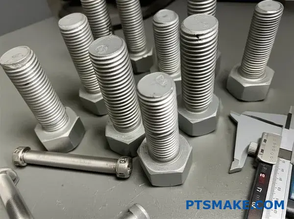
Risolvere i problemi di un lotto di pezzi che non supera l'ispezione.
Quando un lotto di produzione non supera l'ispezione, richiede un'attenzione immediata. Un lotto di bulloni che non supera il test del calibro No-Go è un esempio classico. Questo segnala una deviazione critica.
Spesso il problema risiede nelle specifiche di tolleranza della filettatura. Un approccio sistematico è essenziale per trovare rapidamente la causa principale. Controlli casuali fanno solo perdere tempo prezioso alla produzione.
Lista di controllo per la prima risposta
Iniziamo sempre dalle basi. Questo ci permette di escludere errori semplici prima di immergerci nella diagnostica di macchine complesse. Questo processo strutturato consente di risparmiare tempo.
| Priorità | Punto d'azione | Scopo |
|---|---|---|
| 1 | Lotto di quarantena | Evitare di mescolare i pezzi difettosi con quelli buoni. |
| 2 | Verificare l'indicatore | Assicurarsi che lo strumento di ispezione sia calibrato. |
| 3 | Programma di revisione | Verificare la presenza di modifiche o errori di battitura recenti. |
Seguire queste fasi in modo metodico fornisce un chiaro punto di partenza per qualsiasi indagine.
Isolare la causa principale
Se i controlli iniziali non mostrano nulla, si passa a un'analisi più approfondita. Alla PTSMAKE, il nostro processo di risoluzione dei problemi di lavorazione CNC si basa sulla logica, non sulle congetture. Questo riduce al minimo i tempi di inattività e gli sprechi di materiale per i nostri clienti.
Impostazione della macchina e offset degli utensili
Un'impostazione errata della macchina è un colpevole frequente. Un piccolo errore nell'offset di un utensile può facilmente causare un intero lotto fuori specifica.
Verifichiamo anche la presenza di problemi meccanici. Ad esempio, il gioco degli assi della macchina può introdurre errori difficili da rintracciare. Questi problemi spesso portano a incongruenze nella tolleranza della filettatura.
Analisi approfondita dei componenti
Successivamente, ispezioniamo i componenti fisici del processo. Si tratta di esaminare tutto ciò che tocca il pezzo.
| Componente | Problema potenziale | Fase diagnostica |
|---|---|---|
| Strumento di taglio | L'inserto è usurato o scheggiato | Ispezionare con ingrandimento e sostituire. |
| Materiale Stock | Variazione della durezza | Testare un campione proveniente da un lotto di materiale diverso. |
| Sistema di raffreddamento | Flusso o miscela improprio | Verificare la pressione della pompa e la concentrazione del refrigerante. |
Il refrigerante viene spesso trascurato. Tuttavia, una scarsa lubrificazione può causare l'accumulo di materiale sull'utensile. Questo ha un impatto diretto sul prodotto finito. Diametro del passo21 e può far sì che il pezzo non superi il test del calibro No-Go. Ogni elemento svolge un ruolo cruciale.
Un guasto all'indicatore No-Go indica una deviazione del processo. L'uso di un diagramma di flusso sistematico - dall'impostazione all'utensileria, al materiale e al refrigerante - è il modo più efficiente per individuare il problema, ridurre gli scarti e ripristinare rapidamente la produzione.
L'indicatore No-Go entra di qualche giro. È accettabile?
Questo è un classico dilemma di ispezione. L'indicatore No-Go non dovrebbe entrare, ma lo fa. Solo per un paio di giri. Allora, il pezzo è un rottame?
La risposta semplice è spesso "no". Ma la vera risposta è più complessa. Richiede di guardare oltre la semplice mentalità "pass/fail".
L'area grigia dell'ispezione
Molti standard forniscono regole chiare. Tuttavia, l'applicazione pratica può creare ambiguità. L'uso finale del pezzo è un fattore critico.
| Risultato dell'ispezione | Pensiero iniziale | La realtà |
|---|---|---|
| Il No-Go entra in 2 turni | Bocciatura | Dipende dallo standard e dalla funzione. |
| Il calibro Go si adatta | Passo | Questa parte è corretta. |
Comprendere il Regolamento ufficiale
Norme come ASME B1.2 e ISO 1502 offrono una guida. In genere stabiliscono che l'indicatore No-Go non deve compiere più di tre giri. Questa regola è spesso chiamata "regola dei tre giri".
Questa regola esiste per un motivo. Tiene conto del piccolo smusso o raggio all'inizio di una filettatura. Una leggera entrata è ammessa.
Oltre lo standard: Rischio funzionale
Tuttavia, seguire ciecamente una regola non è sufficiente. Dobbiamo valutare il rischio funzionale. Noi di PTSMAKE chiediamo sempre al cliente l'applicazione del pezzo. La chiave è capire come il diametro del passo22 la variazione influisce sulle prestazioni.
Considerate i seguenti fattori:
| Fattore | Applicazione ad alto rischio (ad esempio, aerospaziale) | Applicazione a basso rischio (ad esempio, apparecchio) |
|---|---|---|
| Sicurezza | Critico. La stretta osservanza è fondamentale. | Non critico. È possibile un maggiore margine di manovra. |
| Carico | Elevate sollecitazioni. È necessario un perfetto ingranamento della filettatura. | Basso livello di stress. Sono accettabili variazioni minime. |
| Ambiente | Vibrazioni elevate. Le filettature non devono allentarsi. | Statico. Minore rischio di guasti. |
Valutare questi aspetti aiuta a prendere una decisione consapevole. Un'adeguata tolleranza di filettatura non è solo una questione di calibro, ma anche la garanzia che il pezzo funzioni perfettamente nell'ambiente in cui è destinato.
L'ingresso parziale di un indicatore di divieto di transito è un problema comune. Gli standard forniscono una base di riferimento, come la regola dei tre giri. Tuttavia, la decisione finale deve sempre basarsi sull'applicazione funzionale del pezzo e sui rischi associati.
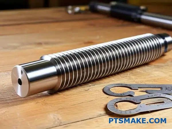
In che modo la produzione additiva potrebbe cambiare la tolleranza delle filettature?
La fabbricazione additiva (AM) sta ridisegnando la progettazione dei componenti. Si spinge ben oltre i confini della lavorazione tradizionale. Cosa significa questo per un elemento fondamentale come la filettatura di una vite?
La promessa dei fili stampati in 3D
L'AM consente un'incredibile libertà di progettazione. Possiamo creare filettature integrate direttamente in parti complesse. Questo riduce i tempi di assemblaggio e i potenziali punti di guasto.
Considerazioni chiave
Tuttavia, questa tecnologia comporta nuove sfide. La finitura superficiale è diversa. Anche le proprietà del materiale possono variare. Entrambi hanno un impatto significativo sulla tolleranza della filettatura.
| Caratteristica | Lavorazione tradizionale | Fabbricazione additiva |
|---|---|---|
| Libertà di progettazione | Limitato dall'accesso agli strumenti | Quasi senza limiti |
| Scelta del materiale | Leghe/plastiche consolidate | Crescita ma proprietà diverse |
| Finitura superficiale | Alto, ben controllato | Spesso più ruvido, necessita di post-elaborazione |
La produzione additiva apre un nuovo libro di giochi per la progettazione delle filettature. Non siamo più limitati agli standard stabiliti da maschi e filiere. Questa tecnologia cambia radicalmente il nostro approccio.
Opportunità nella produzione additiva
Forme di filettatura non standard
Immaginate di creare un profilo di filettatura perfettamente ottimizzato per un carico specifico. Con l'AM possiamo progettare filettature asimmetriche o a passo variabile. Questo non è possibile con la tradizionale lavorazione CNC. Nei progetti passati dell'PTSMAKE, questo ha risolto sfide ingegneristiche uniche.
Caratteristiche di bloccaggio integrate
Possiamo anche stampare elementi di bloccaggio direttamente nel pezzo. Questo elimina la necessità di rondelle di bloccaggio separate o di adesivi chimici. Semplifica l'assemblaggio e aumenta l'affidabilità in ambienti ad alta vibrazione.
Superare gli ostacoli
La sfida più grande è la finitura superficiale. Le linee di livello tipiche della stampa 3D creano una superficie ruvida. Ciò influisce direttamente sull'innesto e sulla resistenza della filettatura. Il materiale Anisotropia23 significa anche che le proprietà possono variare in base all'orientamento della costruzione.
Questa variabilità influisce sulla capacità del processo. Per ottenere una tolleranza costante della filettatura con l'AM è necessario un attento controllo del processo. Spesso sono necessarie fasi di post-elaborazione.
| Sfida | Soluzione potenziale |
|---|---|
| Finitura superficiale grezza | Lavorazione, maschiatura o levigatura chimica |
| Variabilità del processo | Monitoraggio in-process, test sui materiali |
| Anisotropia del materiale | Orientamento strategico dei pezzi durante la costruzione |
La produzione additiva consente di realizzare filettature innovative, come profili personalizzati e caratteristiche integrate. Tuttavia, per ottenere una tolleranza precisa della filettatura è necessario superare le sfide della finitura superficiale e del controllo del processo. La post-elaborazione è spesso necessaria per soddisfare le specifiche.
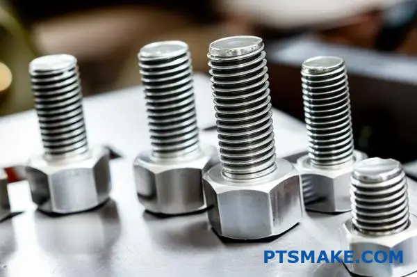
Spiegare la tolleranza "6g" e "6h" a un nuovo stagista.
Benvenuti nel team! Affrontiamo una domanda comune sulle tolleranze delle filettature: 6g" contro "6h". Potrebbe sembrare confuso, ma una semplice analogia lo rende chiaro.
L'analogia del parcheggio
Considerate la dimensione nominale di una filettatura come una linea di parcheggio. La tolleranza 'h' è come parcheggiare l'auto esattamente su quella linea. Si tratta di un accoppiamento perfetto, senza spazi vuoti.
La tolleranza "g" è diversa. Significa parcheggiare l'auto leggermente all'interno della linea. In questo modo si lascia intenzionalmente un piccolo spazio garantito. Perché? Ci arriveremo.
In sintesi
Ecco una semplice ripartizione.
| Classe di tolleranza | Analogia | Caratteristica di adattamento |
|---|---|---|
| 6h | Parcheggio in linea | Accogliente, senza indennità |
| 6g | Parcheggio all'interno della linea | Crea una lacuna specifica |
Questa piccola differenza nella tolleranza della filettatura ha un impatto enorme sull'assemblaggio.
Il "perché" del divario
Quindi, perché mai dovremmo volere uno spazio vuoto? Lo spazio creato dalla tolleranza "6g" non è sprecato. È stato progettato per uno scopo specifico: i rivestimenti superficiali.
Immaginate di aver lavorato un bullone perfetto con tolleranza '6h'. Si adatta perfettamente al dado. Ora, cosa succede se lo inviate per la zincatura o per un altro rivestimento protettivo?
La placcatura aggiunge un sottile strato di materiale. I nostri test dimostrano che può trattarsi di pochi micrometri. Ora il vostro bullone "perfetto" è leggermente troppo grande. Non si adatta più al dado. Questo è un errore costoso che noi di PTSMAKE aiutiamo i nostri clienti a evitare.
Deviazione fondamentale nella pratica
Questa lacuna intenzionale è chiamata deviazione fondamentale24. Per un adattamento 'h', la deviazione fondamentale è pari a zero. La zona di tolleranza si trova proprio sulla dimensione nominale.
Per un adattamento "g", si ha una deviazione negativa. L'intera zona di tolleranza viene spostata al di sotto della dimensione nominale, garantendo questo spazio. In questo modo, anche dopo la placcatura, la filettatura non supererà la dimensione nominale e si assemblerà senza problemi.
La scelta della giusta classe di adattamento è fondamentale per i pezzi funzionali. Si tratta di pianificare l'intero processo produttivo, non solo la fase di lavorazione.
| Scenario di applicazione | Tolleranza consigliata | Motivazione |
|---|---|---|
| Chiusura standard non rivestita | 6h | Offre una vestibilità standard e ravvicinata. |
| Elementi di fissaggio che richiedono la placcatura | 6g | Lascia spazio allo spessore del rivestimento. |
| Alta temperatura, rischio di incollaggio | 6g | La fessura consente di espandersi. |
In breve, '6h' è per un adattamento standard, non placcato, alla dimensione nominale. 6g" crea una piccola fessura intenzionale, essenziale per fare spazio alle finiture successive alla lavorazione, come la placcatura, assicurando che i pezzi si adattino correttamente dopo il trattamento.
Migliorare il successo della tolleranza della filettatura con la competenza di PTSMAKE
Siete pronti a risolvere le vostre sfide più difficili in termini di tolleranza della filettatura e ingegneria di precisione? Contattate PTSMAKE per un preventivo veloce ed esperto: sperimentate la produzione B2B di fiducia che fornisce pezzi lavorati a CNC e stampati a iniezione impeccabili ed economici, ogni volta. Fate il passo successivo: Inviate oggi stesso la vostra richiesta a PTSMAKE!

Scoprite come cambiano le proprietà dei materiali e perché è importante per una produzione di pezzi costante e di alta qualità. ↩
Comprendete questo meccanismo critico di rottura per migliorare la longevità dei dispositivi di fissaggio. ↩
Esplora una guida dettagliata su come questo influisce sull'impegno e sulla resistenza del filo. ↩
Comprendere il principio ingegneristico fondamentale che rende possibile la moderna produzione di massa e le catene di fornitura globali. ↩
Capire come l'LMC viene utilizzato per garantire l'assemblaggio e il funzionamento dei vostri progetti. ↩
Scoprite come questo fenomeno causa il cedimento prematuro dei pezzi e le strategie di progettazione per attenuarlo. ↩
Scoprite come le proprietà direzionali di un materiale possono influenzare il risultato finale della lavorazione. ↩
Scoprite come i codici delle lettere definiscono la posizione della zona di tolleranza rispetto alla dimensione di base. ↩
Scoprite perché una corretta calibrazione dei calibri è fondamentale per garantire che i vostri pezzi siano sempre conformi alle specifiche. ↩
Scoprite come le classi di filettatura e le tolleranze garantiscono il corretto funzionamento degli elementi di fissaggio. ↩
Scoprite come questo parametro chiave definisce la posizione iniziale del filo rispetto alla dimensione di base. ↩
Scoprite come questo principio fondamentale della progettazione dei calibri garantisca il corretto funzionamento dei vostri pezzi. ↩
Scoprite come questa adesione di materiale può causare il grippaggio dei componenti e come prevenirlo. ↩
Comprendete questa metrica chiave per garantire che le vostre misurazioni del filo siano sempre accurate e affidabili. ↩
Scoprite come si usano i calibri master per calibrare e mantenere la precisione dei vostri calibri da lavoro. ↩
Scoprite come la scienza della misurazione assicura che i vostri pezzi soddisfino gli standard di qualità più esigenti. ↩
Scoprite come questo principio fondamentale della produzione assicura che i pezzi si incastrino perfettamente, ogni volta. ↩
Imparate come l'espansione del materiale influisce sull'adattamento dei componenti a diverse temperature. ↩
Scoprite come questa usura specifica può compromettere l'integrità dell'articolazione e come prevenirla. ↩
Comprendere come le proprietà dei materiali influenzino l'efficacia della tenuta sotto pressione. ↩
Capire come questa dimensione critica garantisca l'impegno e la resistenza della filettatura. ↩
Fare clic per comprendere questa dimensione cruciale per garantire l'adattamento e la resistenza della filettatura. ↩
Comprendere come le proprietà del materiale cambiano con la direzione di costruzione e il suo impatto sulla resistenza del pezzo. ↩
Esplorare le basi tecniche della definizione delle posizioni di tolleranza per una comprensione ingegneristica più approfondita. ↩