Finding the right aluminum die casting manufacturer feels overwhelming when part quality, delivery deadlines, and cost targets all hang in the balance. You’ve likely experienced the frustration of receiving parts that don’t meet specifications or dealing with suppliers who can’t scale production when you need it most.
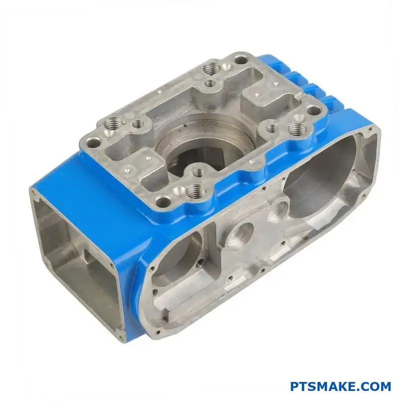
PTSMAKE specializes in custom aluminum die casting parts, offering precision manufacturing from prototype to production with advanced alloy expertise, strict quality control, and scalable production capabilities for industries including automotive, aerospace, electronics, and medical devices.
This comprehensive guide covers everything from fundamental alloy properties and process optimization to defect prevention and cost management. I’ll walk you through the technical principles that drive successful aluminum die casting projects, helping you make informed decisions for your next manufacturing partnership.
What are the core properties of a common die casting alloy?
Let’s talk about A380 aluminum. It is a workhorse in the industry for good reason. Its fundamental properties directly impact the casting process and your final part’s performance.
A380 Alloy’s Foundational Traits
Excellent melt flow is crucial. It ensures the molten metal fills complex mold cavities completely. This simple factor reduces misruns and surface defects.
Quick solidification is another key feature. This allows for faster production cycles. It also helps achieve consistent quality across large batches.
Below are its main mechanical properties.
| Property | Typical Value | Importance for Your Part |
|---|---|---|
| Tensile Strength | 47 ksi | Measures the part’s durability under load. |
| Elongation | 3.5% | Indicates resistance to cracking when bent. |
| Thermal Conductivity | 96 W/m-K | Affects how well the part dissipates heat. |
How Properties Influence Design and Production
The excellent fluidity of A380 is mainly due to its silicon content. This property is essential for producing parts with thin walls and intricate details. We often leverage this for complex electronics housings.
This high silicon level also minimizes shrinkage as the part cools. This means better dimensional accuracy. Your finished parts will match the design specifications more closely.
The solidification process is critical for efficiency. A380’s ability to freeze quickly enables faster cycle times. In high-volume manufacturing, this directly translates to a lower cost per unit.
However, this must be controlled. Rapid cooling can trap air, leading to porosity. This internal defect can weaken the part. Proper process control is everything in aluminum die casting.
Balancing Strength and Flexibility
A380 offers a great balance for many applications. Its tensile strength is suitable for many structural components. But its lower elongation means it is more brittle than some other alloys.
This is a classic engineering trade-off. If a part requires high impact resistance, another alloy might be better. The material’s internal microstructure1 is what defines these mechanical behaviors.
At PTSMAKE, we guide clients through these decisions. Choosing the right alloy is the first step to ensuring your product performs exactly as intended.
A380 alloy’s core properties, from melt flow to tensile strength, are interconnected. They directly influence design possibilities, manufacturing efficiency, and the final part’s real-world performance and reliability.
The Core Role of Thermal Energy Exchange
Die temperature is all about managing heat. Think of it as a controlled energy transfer. The die must be hot enough to let the metal flow, but cool enough to solidify it correctly.
This balance is critical. It directly influences how the molten metal behaves inside the cavity.
Impact on Metal Flow and Solidification
A die that’s too cold will cause the metal to solidify too quickly. This can lead to incomplete filling, known as a cold shut.
Conversely, a die that’s too hot can cause other problems. It can prolong the cycle time and lead to defects like soldering.
| Die Temperature | Effect on Molten Metal | Potential Part Quality Issue |
|---|---|---|
| Too Low | Poor Fluidity | Cold Shuts, Flow Lines |
| Optimal | Controlled Flow | Good Surface Finish, Dense |
| Too High | Excessive Fluidity | Soldering, Blisters, Porosity |
The Principle of Thermal Balance
Achieving consistent quality in production hinges on one key principle: thermal balance. This means the heat removed from the casting with each cycle equals the heat introduced.
Without this balance, the die temperature will drift. It might get progressively hotter or colder, leading to inconsistent part quality. In our projects at PTSMAKE, we use thermal imaging and sensors to monitor and maintain this stability.
This consistent state, or thermal equilibrium2, is the goal. It ensures that the first part and the thousandth part are made under nearly identical conditions. This is vital for processes like high-pressure aluminum die casting where tolerances are tight.
Maintaining this balance requires a well-designed cooling system within the mold. The placement and flow rate of cooling channels are engineered to extract heat precisely where needed.
| Thermal State | Production Outcome |
|---|---|
| Unbalanced | Inconsistent part dimensions, varying defects |
| Balanced | Repeatable quality, stable cycle times, less scrap |
Effective thermal management prevents a cascade of problems. It’s not just about avoiding obvious defects; it’s about guaranteeing the mechanical properties and dimensional accuracy of every single part that comes out of the mold. It is the foundation of reliable manufacturing.
Die temperature governs the thermal exchange between the molten metal and the mold. Maintaining a precise thermal balance is essential for controlling metal flow, solidification, and ultimately preventing defects. This ensures consistent, high-quality part production from start to finish.
What is the primary purpose of draft angles in casting?
From a physics standpoint, a draft angle is a simple solution to complex forces. During ejection, two primary forces work against a clean release.
The Forces of Resistance
Friction is the most obvious opponent. The part’s surface drags against the mold wall. A larger surface area creates more friction.
The second force is vacuum pressure. As the part cools and shrinks, it can create sealed pockets. Pulling the part away from these pockets creates a vacuum that holds it in place.
How Draft Angles Help
A draft angle changes the direction of these forces. It allows the part to move away from the mold wall immediately upon ejection.
| Force Type | Without Draft Angle | With Draft Angle |
|---|---|---|
| Friction | Acts along the entire surface | Greatly reduced at ejection |
| Vacuum | Can form and hold the part | Less likely to form sealed pockets |
This simple taper makes a huge difference.
When molten metal solidifies, it shrinks. This is especially true in processes like aluminum die casting. The part literally grips onto the mold’s cores and internal features. This creates immense friction and adhesion3 between the two surfaces.
Overcoming Shrinkage and Friction
Without a draft angle, the ejection pins must apply force to overcome this static friction. This is like dragging a heavy box across a rough floor. The force required can be high enough to break, bend, or scratch the part.
A draft angle fundamentally changes this dynamic. The moment the ejection system moves, the part’s tapered walls separate from the mold walls.
This turns a high-friction vertical drag into a smooth, low-resistance angled release. The force is no longer fighting the entire surface at once.
The Vacuum Effect Explained
Imagine a deep, straight-walled pocket in a mold. As the metal shrinks, it might pull away slightly from the bottom but still seal against the sides. When the ejector pins push, a vacuum is created in that gap. This vacuum can hold the part with surprising force, preventing its release. The draft angle ensures an air gap can form instantly, breaking any potential vacuum seal.
At PTSMAKE, we analyze these forces carefully. We ensure every feature has the optimal draft for a damage-free release.
Draft angles are a crucial design element rooted in physics. They redirect friction and prevent vacuum lock during ejection. This ensures the part is released smoothly from the mold without damage or excessive force, protecting both the part and the tool.
What defines solidification in thin versus thick sections?
The core principles are heat transfer and volumetric contraction. How a part cools defines its final properties and internal structure.
Heat Transfer Dynamics
Thin sections have a large surface area-to-volume ratio. This allows internal heat to escape very quickly.
Thick sections retain heat much longer. This slow cooling rate has significant consequences for the final part’s integrity.
Comparing Solidification Outcomes
The difference in cooling creates vastly different internal structures. This is a critical factor in part design and performance.
| Feature | Thin Section | Thick Section |
|---|---|---|
| Cooling Rate | Very Fast | Slow |
| Grain Structure | Fine, uniform | Coarse, varied |
| Solidification Time | Rapid | Prolonged |
The Challenge of Shrinkage Porosity
As molten metal cools, it shrinks. In thick sections, the outer surface solidifies first, forming a solid shell.
The liquid metal inside continues to cool and shrink. Without extra material to fill the space, this creates voids, or porosity.
Why This Matters in Manufacturing
Porosity is a serious defect that weakens the part. It creates stress concentration points that can lead to failure under load.
This is a major concern in processes like aluminum die casting, where strength and reliability are paramount for our clients.
Grain Structure and Its Impact
Rapid cooling in thin sections restricts crystal formation. This results in a fine, strong, and dense grain structure.
Slower cooling in thick sections allows for more extensive crystal formation. This can lead to dendritic growth4, creating a coarser, and often weaker, internal structure.
The Role of Gates and Risers
To combat shrinkage in thick sections, we use gates and risers. These are channels and reservoirs that hold extra molten metal.
They feed the main casting as it solidifies and shrinks. This process fills potential voids and ensures a solid, dense part. At PTSMAKE, optimizing gate and riser design is key to quality.
In summary, section thickness dictates cooling speed. This directly impacts grain structure and the risk of defects like porosity. Thin sections are generally stronger, while thick sections need careful design considerations to ensure soundness and prevent internal flaws.
What are the main categories of aluminum die casting defects?
To solve a problem, you first need to name it. This is true for aluminum die casting defects. A clear classification system helps us diagnose issues quickly.
Think of it as a diagnostic tree. It simplifies complex problems.
A Framework for Diagnosis
We group defects into four main families. This structure helps pinpoint the root cause, whether it’s in the process, material, or tooling design. Each category points to a different area of the manufacturing cycle.
| Defect Category | Common Examples |
|---|---|
| Porosity | Gas Porosity, Shrinkage Porosity |
| Surface Defects | Cold Shuts, Flow Lines, Blisters |
| Dimensional Defects | Warpage, Sink Marks |
| Cracking | Hot Tears, Stress Cracks |
This approach creates a clear path from problem to solution.
Understanding these categories is the first step. At PTSMAKE, we use this framework to streamline our troubleshooting process, ensuring consistent quality for every part. It provides a shared language for our engineers and clients.
Diving Deeper into Defect Types
Each category has specific defects with distinct causes. Let’s break them down. This detailed view is crucial for effective problem-solving in any aluminum die casting project.
Porosity Problems
Porosity is essentially trapped voids within the casting. Gas porosity comes from dissolved gases trapped during solidification. Shrinkage porosity occurs when sections of molten metal are isolated before they fully solidify.
Surface Imperfections
These defects affect the part’s appearance and finish. Cold shuts happen when two molten metal streams fail to fuse properly. Blisters are raised surface bubbles from trapped gases just below the skin. Proper solidification5 control is key here.
Dimensional Inaccuracies
Warpage is a distortion where the part deviates from its intended shape, usually due to internal stresses from uneven cooling. Sink marks are depressions on the surface, often opposite thick sections like ribs or bosses.
Cracking Concerns
Hot tears are fractures that appear at high temperatures as the casting cools and contracts. Stress cracks can develop later due to residual internal stresses or external loads applied after casting.
| Defect Type | Primary Cause |
|---|---|
| Gas Porosity | Trapped air or gas from lubricant |
| Cold Shuts | Low melt temperature or slow injection |
| Warpage | Uneven cooling or poor part ejection |
| Hot Tears | High thermal stress during cooling |
Classifying defects into porosity, surface, dimensional, and cracking categories creates a powerful diagnostic tool. This structured approach helps identify root causes faster, leading to more effective and reliable solutions in aluminum die casting.
What are common aluminum alloys and their practical tradeoffs?
Choosing the right aluminum alloy is a critical decision. It directly impacts your part’s performance, durability, and final cost. It’s not about finding the "best" alloy. It’s about finding the right one for your specific needs.
Let’s compare four of the most common alloys we work with at PTSMAKE. This practical map helps clarify their specific trade-offs.
Quick Comparison of Common Alloys
Here’s a high-level look at their primary strengths.
| Alloy | Key Feature | Best For |
|---|---|---|
| A380 | Good All-Rounder | General-purpose, cost-effective parts |
| ADC12 | A380 Equivalent | Similar applications, Japanese standard |
| A360 | Corrosion Resistance | Marine, outdoor, harsh environments |
| A413 | High Fluidity | Complex, thin-walled components |
Digging Deeper into Trade-offs
Now, let’s explore the nuances. In past projects at PTSMAKE, these details have often been the deciding factor for our clients. Each alloy forces a compromise between different properties.
A380 and ADC12: The Industry Workhorses
A380 is the go-to choice for most aluminum die casting projects. It provides an excellent balance of casting ease, mechanical properties, and cost-effectiveness. ADC12 is the Japanese Industrial Standards (JIS) equivalent, and for most practical purposes, they are interchangeable.
A360: Superior Corrosion Resistance
If your part will be exposed to moisture or harsh elements, A360 is a strong contender. Its lower copper content gives it superior corrosion resistance. It also provides better pressure tightness. The trade-off? It can be slightly more difficult to machine than A380.
A413: The Fluidity Champion
For parts with intricate details and very thin walls, A413 is often the answer. Its high silicon content creates a composition near the eutectic6 point, giving it exceptional fluidity to fill complex mold cavities. However, this comes at the cost of slightly lower tensile and yield strength.
Mechanical and Physical Property Comparison
This table, based on our internal testing and data, shows a more detailed comparison.
| Property | A380 / ADC12 | A360 | A413 |
|---|---|---|---|
| Tensile Strength (ksi) | 47 | 46 | 42 |
| Yield Strength (ksi) | 23 | 25 | 21 |
| Castability | Excellent | Good | Excellent |
| Corrosion Resistance | Good | Excellent | Good |
| Pressure Tightness | Good | Excellent | Excellent |
| Machinability | Good | Fair | Good |
Your choice hinges on your primary requirement. A380 offers a balanced profile for general use. A360 prioritizes durability in harsh conditions, while A413 is perfect for creating complex, thin-walled parts that require excellent casting flow.
What are the main secondary operations after die casting?
A die-cast part isn’t complete when it exits the mold. It’s just the beginning. A structured workflow transforms this raw casting into a finished product.
This sequence is essential for quality. Each step prepares the part for the next. The journey typically follows a clear path from raw casting to the final, functional component.
The Typical Post-Casting Flow
| Step | Purpose |
|---|---|
| 1. Trimming | Remove excess material. |
| 2. Shot Blasting | Create a uniform surface. |
| 3. Machining | Achieve tight tolerances. |
| 4. Finishing | Apply protective/cosmetic coating. |
This process ensures every part meets precise design specifications.
Understanding the post-casting workflow is key to managing production and ensuring quality. Each stage has a specific role in refining the part from its as-cast state to its final form. It’s a systematic progression we follow at PTSMAKE to guarantee predictable, high-quality results.
Trimming: The First Cut
The first operation is trimming. A trim press cleanly shears off excess material. This includes the runners, overflows, and flash left from the casting process. This step creates the part’s basic net shape, preparing it for subsequent operations.
Shot Blasting: Creating a Uniform Surface
Next, shot blasting removes any minor imperfections. It propels fine media against the part. This process creates a clean, uniform matte finish. This surface is ideal for subsequent painting, coating, or other finishing treatments.
Precision Machining: Achieving Final Tolerances
For features requiring tight tolerances, machining is essential. CNC machines can drill, tap threads, or mill surfaces that the casting process cannot form precisely. This step ensures the part meets all critical dimensional requirements for assembly and function.
Finishing: The Protective and Aesthetic Layer
The final stage is applying a finish. This protects the part from corrosion and enhances its appearance. For aluminum die casting, options like powder coating or anodizing7 are common.
| Finishing Type | Primary Benefit | Best For |
|---|---|---|
| Powder Coating | Durability, Color Options | High-wear applications |
| Anodizing | Corrosion Resistance | Aluminum parts |
| Chromating | Corrosion Protection, Primer | Electrical conductivity |
This systematic workflow ensures that every die-cast part moves efficiently from a raw casting to a precision component. Each step, from trimming excess material to applying the final finish, is crucial for achieving the required quality, function, and appearance.
How do you adapt a process for a high-silicon aluminum alloy?
High-silicon aluminum alloys are tough. They are known for being very abrasive on tooling. This makes the aluminum die casting process tricky.
Success requires more than just changing settings. It demands a full strategy. You must account for lower fluidity and protect your molds from rapid wear.
Adjusting for Abrasiveness
We start by adjusting key parameters. This helps manage the alloy’s characteristics. Higher temperatures for both the metal and the die are essential for good flow.
Key Parameter Shifts
| Parameter | Standard Al-Alloy | High-Si Al-Alloy |
|---|---|---|
| Metal Temp | 660-680°C | 700-730°C |
| Die Temp | 180-220°C | 240-280°C |
| Injection Speed | Moderate | Slightly Slower |
These initial changes help ensure the mold fills completely. They prevent defects caused by the alloy’s sluggish nature.
Adapting process parameters is only half the battle. The real challenge with high-silicon alloys is managing tool wear. The abrasive silicon particles act like sandpaper on the mold steel.
At PTSMAKE, we’ve found that a proactive tooling strategy is non-negotiable. Without it, tool life is drastically reduced, leading to higher costs and downtime. This is a critical factor in any high-volume production plan.
A Robust Tooling Maintenance Plan
A strict maintenance schedule is your first line of defense. You cannot afford to wait for problems to appear. Regular inspection and servicing are key.
Sample Maintenance Checklist
| Frequency | Task | Purpose |
|---|---|---|
| Every 2,000 Cycles | Visual Inspection | Check for early signs of erosion or galling. |
| Every 5,000 Cycles | Minor Polishing | Restore surface finish in high-wear areas. |
| Every 10,000 Cycles | Full Teardown | Detailed inspection, cleaning, and replacement of worn pins. |
The Role of Advanced Coatings
Even with great maintenance, the base steel needs help. PVD (Physical Vapor Deposition) coatings create a hard, lubricious barrier. This shield protects the mold from the abrasive alloy. The formation of hard intermetallic compounds8 at the tool surface is a major cause of wear, and coatings mitigate this. Choosing the right coating, like TiN or CrN, is vital.
Adapting for high-silicon aluminum involves raising temperatures to improve flow. More importantly, it requires a rigorous mold maintenance schedule and the use of PVD coatings to combat the alloy’s abrasive nature, ensuring tooling longevity and consistent part quality.
How to balance part cost, quality, and production rate?
Making sound business decisions requires technical knowledge. The "fastest" process is not always the most profitable one. Real success comes from balancing competing operational goals.
Let’s analyze a common scenario. Imagine increasing a machine’s cycle time by 10%. This seems like a loss, but what if it eliminates a 2% scrap rate? This simple trade-off can reveal hidden profits.
The Initial Situation
| Metric | Value |
|---|---|
| Cycle Time | 60 seconds |
| Scrap Rate | 2% |
| Output/Hour | 60 parts |
This scenario shows that speed can come at a cost. We need to look deeper than just the production rate to understand the full picture.
Let’s break down the cost-benefit analysis for this situation. We need to quantify the cost of scrap versus the cost of a slower cycle. This is where technical insight directly impacts business outcomes.
In a past project at PTSMAKE involving an aluminum die casting part, we faced this exact issue. The client wanted maximum speed, but tiny defects caused a consistent 2% scrap rate. These scrapped parts weren’t just lost material; they represented wasted machine time, labor, and energy.
Cost-Benefit Analysis
| Factor | Original Process | New Process |
|---|---|---|
| Cycle Time | 60 sec | 66 sec (+10%) |
| Parts per Hour | 60 | ~54.5 |
| Scrap Rate | 2% | 0% |
| Good Parts/Hour | 58.8 | 54.5 |
While the new process produces fewer parts per hour, it produces zero scrap. The key is understanding the Opportunity Cost9 of the lost production time versus the tangible cost of scrapped parts.
If the cost of a single scrapped part is high, eliminating that waste can easily justify the reduced output. We found that the savings from eliminating scrap far outweighed the cost of the slightly lower production rate. This decision increased overall profitability.
This simple analysis shows that a small, controlled slowdown can be a smart business move. It converts wasted resources from scrap into valuable, high-quality parts, improving the bottom line.
A slower, more controlled process can yield higher profitability by eliminating waste. This data-driven approach, which we champion at PTSMAKE, turns technical adjustments into tangible business advantages, proving that efficiency is more than just speed.
Unlock Superior Aluminum Die Casting with PTSMAKE Today
Ready to achieve unparalleled quality, cost-efficiency, and reliability for your aluminum die casting projects? Contact PTSMAKE now for a fast, competitive quote and discover how our expertise can optimize your part performance from prototype to large-scale production. Send your inquiry to get started!

Discover how this internal structure impacts an alloy’s strength and casting behavior for better design outcomes. ↩
Learn how mastering this concept helps optimize your die casting process and reduce scrap rates. ↩
Understand the molecular forces causing parts to stick to mold surfaces. ↩
Understand how crystal formation during solidification impacts the final mechanical properties of your cast parts. ↩
Learn how the cooling and solidification process influences the final mechanical properties of the cast part. ↩
Discover how this specific alloy composition enhances metal flow for detailed castings. ↩
Learn how this electrochemical process improves durability and appearance on aluminum die casting parts. ↩
Understand how these micro-alloys form and impact tool life in high-wear applications. ↩
Understand how choosing one manufacturing option over another impacts your project’s hidden costs. ↩