Custom liquid cooling systems fail when companies choose the wrong cold plate design or manufacturer. Many engineers face delays, poor thermal performance, and reliability issues that compromise their entire cooling system and project timelines.
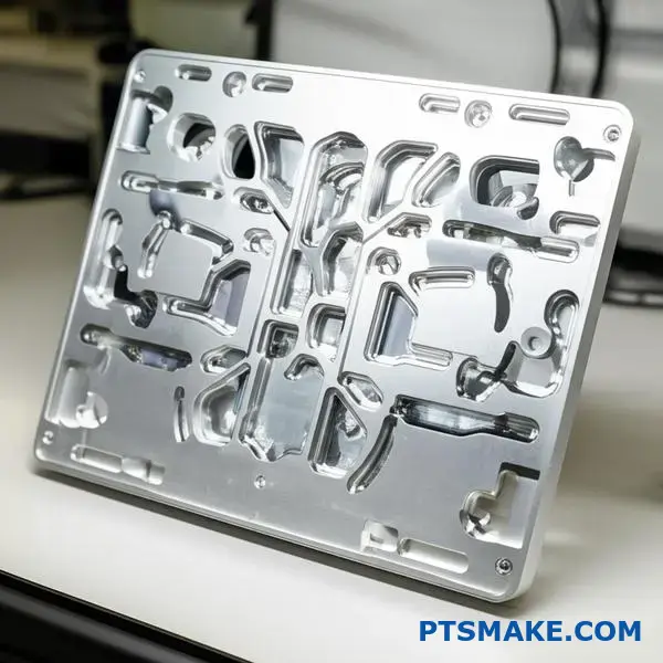
PTSMAKE manufactures custom cold plates using precision CNC machining and advanced manufacturing techniques, delivering reliable liquid cooling solutions from prototype to production for high-performance applications across aerospace, electronics, and automotive industries.
Whether you need basic serpentine designs or complex microchannel geometries, the right cold plate selection depends on your specific heat flux requirements, material constraints, and performance targets. This guide covers the key decisions you’ll face when designing your next liquid cooling system.
What are the main types of cold plate manufacturing methods?
Choosing the right manufacturing method for your cold plate is critical. It directly impacts performance, cost, and system reliability. Your choice depends entirely on your specific thermal and mechanical needs.
Let’s explore the common options for effective cold plate liquid cooling.
Key Manufacturing Approaches
Each method has unique trade-offs. Understanding them is the first step to an optimized design.
| Method | Simplicity | Typical Cost |
|---|---|---|
| Machined/Drilled | High | Low |
| Tube-in-Plate | Medium | Low-Medium |
| Brazed Assembly | Low | High |
| Friction Stir Welding | Medium | High |
This simple comparison guides initial selection.
Deeper Dive into Manufacturing Techniques
Choosing the right technique requires a closer look at the details. In my experience, the application dictates the best path forward.
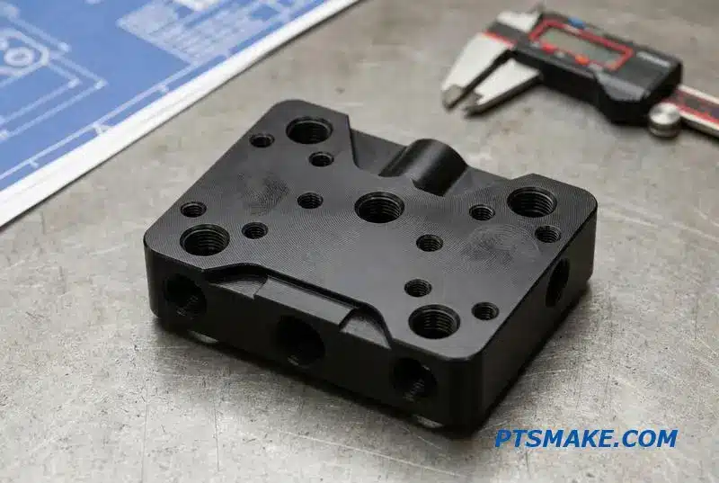
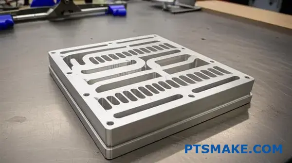
Machined and Drilled Plates
This is the most basic approach. A simple fluid path is drilled into a solid metal plate. It’s cost-effective for prototypes and low-volume production. However, its thermal performance is limited. It works best for applications with low heat densities.
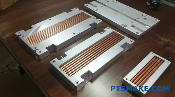
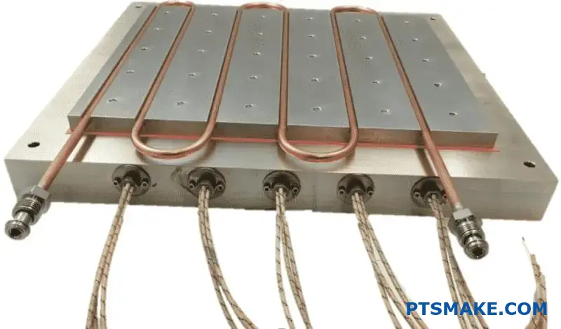
Tube-in-Plate Designs
Here, we embed tubes into a milled channel in the base plate. This method offers better thermal contact and performance than a simple drilled plate. The quality of the connection between the tube and plate is crucial for efficiency.
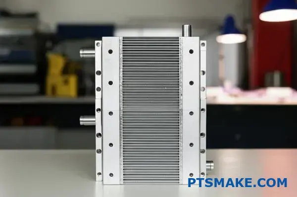
Brazed and Welded Assemblies
For high-performance cold plate liquid cooling, brazed assemblies are often the top choice. They allow for complex internal fin structures, maximizing the surface area for heat transfer. The brazing1 process creates a strong, leak-proof metallurgical bond. At PTSMAKE, we focus on joint integrity to ensure maximum reliability.
Friction Stir Welding (FSW)
FSW is a solid-state joining process. It produces exceptionally strong and void-free joints without melting the base material. This makes it ideal for high-reliability applications where leaks are not an option.
| Feature | Machined | Tube-in-Plate | Brazed | FSW |
|---|---|---|---|---|
| Thermal Performance | Low | Medium | High | Very High |
| Leak Risk | Low | Medium | Low | Very Low |
| Design Flexibility | Low | Medium | High | High |
Selecting the ideal method involves a careful trade-off analysis.
Each cold plate manufacturing method offers a unique balance of cost, performance, and reliability. From simple drilled plates for prototypes to advanced FSW for critical applications, the right choice ensures your system operates efficiently and safely.
How do internal channel designs (serpentine vs. parallel) differ?
When designing for cold plate liquid cooling, the internal channel layout is crucial. The two most common paths are serpentine and parallel. Each has distinct advantages and disadvantages.
A serpentine design uses one long, winding channel. This forces high fluid velocity, which is great for heat transfer. However, it also creates significant pressure drop.
In contrast, a parallel design splits the flow into multiple shorter channels. This drastically reduces pressure drop. But it introduces other risks.
Let’s compare them directly.
| Feature | Serpentine Design | Parallel Design |
|---|---|---|
| Fluid Path | Single, long channel | Multiple, short channels |
| Velocity | High | Low |
| Pressure Drop | High | Low |
| Heat Transfer | Excellent | Good |
Choosing the right design involves balancing trade-offs. It is a critical decision in any cold plate liquid cooling project.
The Serpentine Trade-Off
The long, single path of a serpentine design ensures all fluid travels the same distance. This guarantees consistent flow and temperature distribution along the channel. The high velocity scrubs the thermal boundary layer, boosting heat transfer. But this comes at the cost of requiring a more powerful pump to overcome the high pressure drop.
The Parallel Predicament
A parallel design offers an easy path for the coolant, demanding less from the pump. This is a huge benefit for system efficiency. However, the fluid will naturally favor paths of least resistance. This can lead to some channels receiving less flow than others. This issue of flow maldistribution2 can create hotspots and compromise cooling performance, a problem we have helped many clients solve at PTSMAKE.
Hybrid Designs: The Best of Both Worlds
To balance these factors, we often develop hybrid designs. These can feature a mix of parallel and serpentine sections. For instance, a design might split the flow into a few serpentine paths that run in parallel. This approach helps manage pressure drop while maintaining good flow velocity and distribution.
| Design Type | Primary Advantage | Primary Disadvantage | Best For… |
|---|---|---|---|
| Serpentine | High heat transfer | High pressure drop | High heat-flux components |
| Parallel | Low pressure drop | Risk of maldistribution | Low-pressure systems |
| Hybrid | Balanced performance | More complex to design | Optimized, specific applications |
The choice between serpentine, parallel, or hybrid designs is not arbitrary. It depends entirely on your system’s specific thermal loads, pressure budget, and performance goals. Each design offers a different balance of performance characteristics.
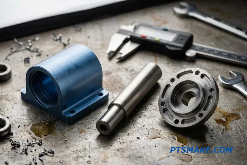
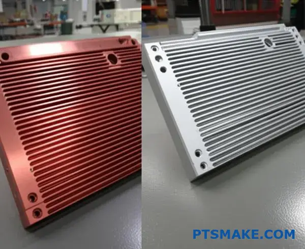
When is copper a better choice than aluminum for cold plates?
Choosing between copper and aluminum isn’t just about material properties. It’s about your specific application’s demands.
High-Performance Scenarios
Copper is the champion for high heat flux situations. Its superior thermal conductivity excels at pulling heat away quickly. This is critical for powerful electronics.
Cost and Weight Constraints
Aluminum is lighter and more cost-effective. It’s often the go-to for weight-sensitive applications. Or for projects with tighter budgets where heat loads are moderate.
Here is a quick comparison:
| Feature | Copper | Aluminum |
|---|---|---|
| Thermal Conductivity | ~400 W/m-K | ~235 W/m-K |
| Density | High | Low |
| Cost | Higher | Lower |
| Best For | High Heat Flux | Weight/Cost Sensitive |
Diving Deeper into Application Needs
The term "high heat flux" means a lot of thermal energy concentrated in a small area. Think of modern CPUs, GPUs, or laser diodes. Here, heat must be spread and removed instantly to avoid damage.
Copper’s ability to spread this heat prevents damaging hot spots. This is a primary reason it’s chosen for demanding cold plate liquid cooling systems.
Material Compatibility Concerns
However, copper isn’t a simple drop-in upgrade. You must consider the entire liquid cooling loop. Mixing copper with aluminum parts can cause serious issues. This is due to potential corrosion if the wrong coolant is used. We always advise clients to check full system compatibility.
Low thermal resistance3 is the ultimate goal. Your material choice is a huge part of achieving it effectively.
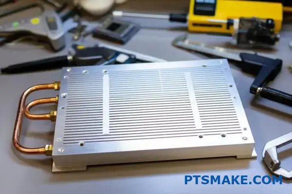
A Hybrid Approach
Sometimes, the best solution combines both materials. For instance, embedding copper tubes within an aluminum cold plate offers a balance. It provides targeted high-performance cooling while managing overall weight and cost.
This table shows common pairings and considerations:
| Cold Plate | Other Components | Key Consideration |
|---|---|---|
| Copper | Copper/Brass | Ideal for maximum performance |
| Aluminum | Aluminum | Cost-effective, avoids mixing metals |
| Copper | Aluminum | Requires specific corrosion inhibitors in coolant |
In past projects at PTSMAKE, a thorough system analysis has always prevented costly future failures.
The decision hinges on a careful trade-off. You must balance thermal performance against weight, cost, and material compatibility. Copper excels in heat transfer, but aluminum offers practical advantages for many applications. This balance is key to successful cold plate liquid cooling design.
What are the trade-offs between different coolant types?
Choosing the right coolant is critical. It directly impacts performance and system longevity. It’s not just about what cools best.
You must consider cost, safety, and compatibility with your hardware. Each option has clear pros and cons.
Key Coolant Categories
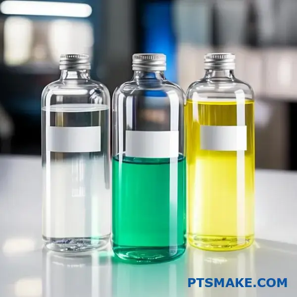
Deionized (DI) Water
DI water offers superior thermal performance. But it can be corrosive over time and may promote biological growth if not treated properly.
Water-Glycol Mixtures
These mixtures provide excellent freeze protection. They also inhibit corrosion but slightly reduce cooling efficiency compared to pure DI water.
Dielectric Fluids
These are non-conductive. This makes them perfect for direct contact with electronics. However, their thermal performance is generally lower.
| Coolant Type | Key Advantage | Key Disadvantage |
|---|---|---|
| Deionized Water | Highest Thermal Performance | Corrosive / Bio-risk |
| Water-Glycol | Freeze/Corrosion Protection | Lower Performance |
| Dielectric Fluid | Electrically Insulating | Lowest Performance |
Making the right choice involves balancing these trade-offs. It’s a frequent topic of discussion in our projects at PTSMAKE. A decision matrix is a useful tool.
Creating a Decision Matrix
This matrix helps clarify priorities. It maps coolant properties against your project’s specific needs, like those for a cold plate liquid cooling system.
Core Decision Factors
- Temperature Range: Will the system face freezing conditions? This immediately points toward a glycol mixture.
- Cost: DI water is inexpensive initially. However, maintenance and additives can increase long-term costs. Dielectric fluids are the most expensive option.
- Electrical Needs: If the coolant might touch electronics, a dielectric fluid is the only safe choice. This is non-negotiable for some applications. The fluid’s viscosity4 also affects pump selection and power draw.
In our experience, a simple chart helps clients visualize these trade-offs clearly. It removes ambiguity from the decision-making process.
| Factor | Deionized Water | Water-Glycol | Dielectric Fluid |
|---|---|---|---|
| Operating Temp. | 0°C to 100°C | -50°C to 120°C | -80°C to 200°C+ |
| Relative Cost | Low | Medium | High |
| Electrical Risk | High (if contaminated) | High | Very Low |
| Thermal Perf. | Excellent | Good | Fair |
Choosing a coolant involves balancing thermal performance against operational safety and budget. Your application’s specific needs—from temperature range to electrical risk—will determine the ideal fluid, ensuring system reliability and efficiency.
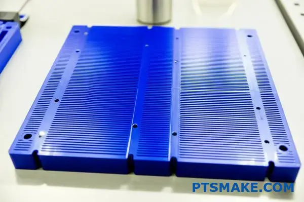
What distinguishes a microchannel cold plate from a standard one?
Microchannel cold plates represent a significant advancement in cold plate liquid cooling. Their main feature is incredibly small fluid channels.
Defining "Micro"
These channels have a hydraulic diameter typically under 1 millimeter. This small size is the key to their performance.
It creates an extremely high surface-area-to-volume ratio. This maximizes contact between the coolant and the plate’s surface.
This superior contact leads to a very high heat transfer coefficient. This makes them ideal for removing intense, concentrated heat.
| Feature | Microchannel Cold Plate | Standard Cold Plate |
|---|---|---|
| Channel Size | < 1mm | > 1mm |
| Surface Area | Very High | Moderate |
| Heat Transfer | Excellent | Good |
| Best For | High Heat Flux | General Purpose |
This technology is perfect for demanding applications. Think of laser diodes or high-performance CPUs where heat management is critical.
The Physics Behind Performance
The secret to a microchannel cold plate’s power is its physics. The immense internal surface area allows for rapid heat absorption. Heat moves quickly from the device into the liquid coolant.
This structure significantly boosts the heat transfer coefficient. In projects we’ve worked on, this can make cooling several times more effective than standard designs for the same footprint. This is a critical factor for modern cold plate liquid cooling systems.
The Manufacturing Challenge
However, creating these channels is not simple. It requires extreme precision. Channels must be uniform to ensure consistent flow and prevent blockages. This is where our expertise in precision CNC machining at PTSMAKE becomes vital.
The Major Trade-Off: Pressure Drop
But there’s a significant drawback: pressure drop. Forcing liquid through such tiny passages creates high resistance. This is similar to drinking a thick milkshake through a very narrow straw. The effective hydraulic diameter5 directly impacts this resistance.
This means you need a more powerful pump. A stronger pump consumes more energy. It can also add noise and complexity to the overall system design, which must be factored in early.
| Aspect | Advantage | Disadvantage |
|---|---|---|
| Performance | Superior heat dissipation | – |
| System Impact | Compact, efficient footprint | Requires powerful pump |
| Energy Use | – | Higher pump energy consumption |
| Cost | – | Potentially higher system cost |
Microchannel cold plates offer unmatched cooling for high-heat-flux devices. However, this performance comes at the cost of a significant pressure drop. This trade-off requires careful consideration in the overall system design, balancing cooling needs with pump power and energy efficiency.
What are the applications for 3D printed cold plates?
Additive manufacturing truly changes the game for cold plates. It allows us to create designs that are simply impossible with traditional machining methods.
We can now build highly optimized internal structures. This approach significantly boosts thermal performance. Think of intricate lattices or complex channels.
These geometries are perfect for rapid prototyping. They also fit applications with unusual shapes. Here, maximum performance is the primary goal. This makes 3D printing a powerful tool for advanced cold plate liquid cooling.
| Feature | Traditional Machining | 3D Printing (AM) |
|---|---|---|
| Geometry | Simple, straight channels | Complex, organic shapes |
| Prototyping | Slow, high setup cost | Fast, cost-effective |
| Customization | Limited | Highly flexible |
| Performance | Standard | Optimized for specific needs |
3D printing, or additive manufacturing, unlocks incredible design freedom. We are no longer limited by what a CNC machine can cut. This opens the door to superior thermal management solutions for our clients.
One key advantage is creating conformal channels. These channels precisely follow the shape of the heat source. This minimizes the distance heat must travel. This design drastically improves cooling efficiency. It is a true custom-fit solution for heat.
We also explore complex internal structures like lattices. A gyroid6 is a great example. It’s a triply periodic minimal surface. It offers a huge surface area in a small volume, which means much better heat transfer.
This technology is perfect for rapid prototyping. In past projects at PTSMAKE, we’ve used it to test multiple designs in days, not weeks. It helps us find the optimal cold plate liquid cooling solution much faster for our partners.
When performance is absolutely non-negotiable, 3D printing is the answer. This is especially true for industries like aerospace or high-performance computing. Here, every degree of cooling matters more than the initial manufacturing cost.
| Geometry Type | Key Benefit | Ideal Application |
|---|---|---|
| Conformal Channels | Follows heat source shape | Non-flat electronics, GPUs |
| Gyroid Lattices | High surface area-to-volume ratio | High heat-flux devices |
| Pin-Fin Arrays | Low pressure drop | Systems with pump limitations |
Additive manufacturing enables complex geometries like conformal channels for superior performance. It is ideal for rapid prototyping and specialized applications where cooling efficiency is the top priority, making it a powerful tool for advanced thermal management solutions.
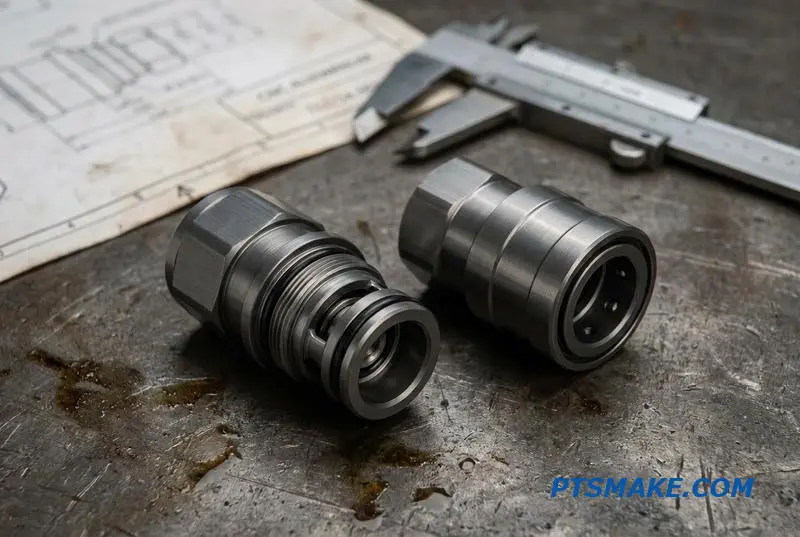
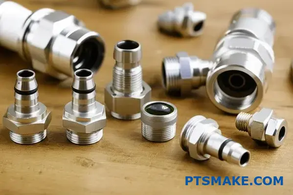
Classifying Fittings by Function and Reliability
Choosing the right fitting is critical. It’s about more than just connecting tubes. It’s about ensuring system integrity and reliability. Your choice impacts performance and maintenance down the line.
Basic Fitting Types
There are three main categories. Each serves a different purpose. They balance security, ease of use, and cost. Let’s look at the options.
| Fitting Type | Primary Use | Pressure Rating |
|---|---|---|
| Barbed | Low-pressure, simple setups | Low |
| Compression | High-pressure, secure seals | High |
| Quick-Disconnect | Serviceable systems | Varies |
Barbed fittings are the simplest. They are great for quick prototypes. But for mission-critical systems, I always recommend a more secure option.
A Deeper Dive into Materials and Standards
Function is just one part of the story. Material and thread standards are equally important for long-term performance, especially in a high-demand cold plate liquid cooling system.
Material Selection
The material dictates durability and chemical compatibility. Brass is a popular all-around choice. It offers excellent thermal conductivity and corrosion resistance.
Plastics like Acetal (POM) are cost-effective. They are good for applications where weight is a concern. However, their long-term durability under heat and pressure must be considered. Stainless steel offers the highest strength and corrosion resistance but comes at a premium. Some applications might require special surface treatments like anodization7 to improve surface hardness.
At PTSMAKE, we often CNC machine custom brass fittings for clients. This ensures perfect thread geometry and sealing surfaces, which is crucial for preventing leaks.
Thread Standards
Threads create the mechanical seal. Using mismatched threads is a common cause of failure. The two dominant standards you’ll see are:
| Thread Standard | Description | Sealing Method |
|---|---|---|
| G1/4" | British Standard Pipe Parallel | O-ring or gasket |
| NPT | National Pipe Taper | Tapered threads |
G1/4" is the de facto standard in PC liquid cooling. Its parallel threads rely on an O-ring for a perfect seal. NPT threads seal by deforming into each other, which requires thread sealant.
Choosing the right fitting ensures your system is secure and serviceable. From simple barbed fittings to robust compression types, the selection depends on pressure, material compatibility, and maintenance needs. Thread standards like G1/4" and NPT are also crucial for a leak-free seal.
How are cold plates classified for high vs. low power density?
Classifying a cold plate starts with one question: how much heat are you moving? Power density is the key metric. It dictates everything from design to manufacturing.
We break it down into three main categories. This helps us select the right approach for any thermal challenge. A simple classification ensures efficiency.
Understanding Power Density Levels
Each level requires a specific technology. Matching the tech to the density is crucial for performance and cost.
| Power Density Level | Range (W/cm²) | Typical Technology |
|---|---|---|
| Low | < 50 | Tube-in-Plate, Serpentine |
| High | 50 – 300 | FSW with Internal Fins |
| Very High | > 300 | Microchannel, Jet Impingement |
This framework guides the initial design of any effective cold plate liquid cooling system.
Let’s dig deeper into these classifications. The choice you make directly impacts performance, cost, and manufacturing complexity. It’s a critical decision in product development.
Low Power Density Solutions
For applications under 50 W/cm², simplicity wins. Tube-in-plate or serpentine channel designs are often sufficient. They are cost-effective and relatively easy to manufacture. We see these in many standard industrial systems.
High Power Density Solutions
When you move into the 50-300 W/cm² range, things get more complex. Standard designs can’t keep up. You need more surface area for heat transfer. This is where technologies like Friction Stir Welded (FSW) plates with complex internal fins shine. Manufacturing these requires precision.
Very High Power Density Solutions
Above 300 W/cm², we enter specialized thermal management. This is for extreme applications like high-performance computing or advanced lasers. Here, microchannel cold plates or even jet impingement8 systems are necessary. These designs maximize fluid-to-surface interaction, but the manufacturing tolerances are incredibly tight.
Here’s a more detailed comparison:
| Technology | Power Density (W/cm²) | Key Feature | Manufacturing Note |
|---|---|---|---|
| Serpentine Tube | < 50 | Simple, continuous fluid path | Easy to bend and braze into place |
| FSW with Fins | 50 – 300 | High internal surface area | Requires precise CNC machining and welding |
| Microchannel | > 300 | Massive surface area in a small volume | Demands advanced fabrication like etching or bonding |
In summary, selecting the right cold plate is a balancing act. Power density dictates the necessary design complexity. This choice ranges from simple tube layouts for low heat loads to advanced microstructures for the most demanding thermal challenges.
What is the methodology for designing flow channel geometry?
Designing flow channel geometry is not a one-shot process. It’s an iterative cycle of creation, analysis, and refinement. This method ensures the final design is truly optimized.
We begin with a simple, baseline layout. Often, this is a parallel channel design. It serves as our starting point for evaluation.
The Iterative Cycle
The core idea is to continuously improve. We modify the design based on performance data. This loop continues until we meet all targets.
| Step | Action | Goal |
|---|---|---|
| 1 | Design | Create an initial geometry (e.g., parallel channels). |
| 2 | Analyze | Predict performance using calculations or CFD. |
| 3 | Modify | Adjust geometry to improve results. |
| 4 | Repeat | Continue the cycle until targets are met. |
This structured approach avoids guesswork. It builds toward an effective solution methodically.
The iterative process is where theory meets practical application. It’s how we turn a concept into a high-performance part, especially for complex systems like cold plate liquid cooling.
Predicting Performance
We rely heavily on analysis to guide modifications. This step is critical. We use calculations or software to predict how the design will perform.
This analysis focuses on key metrics. The goal is to see how heat moves and how much resistance the fluid encounters. This is where tools for Computational Fluid Dynamics9 become invaluable. They simulate fluid behavior within the channels.
Modifying the Geometry
Based on the analysis, we make targeted changes. We don’t change things randomly. Each modification aims to solve a specific problem identified in the simulation.
Our analysis might show poor heat transfer in some areas. Or maybe the pressure drop is too high for the client’s pump.
Common Adjustments and Their Effects
| Modification | Primary Effect on Heat Transfer | Primary Effect on Pressure Drop |
|---|---|---|
| Increase Channel Width | Decreases | Decreases Significantly |
| Increase Channel Depth | Increases | Decreases |
| Add/Increase Fin Density | Increases Significantly | Increases Significantly |
At PTSMAKE, we repeat this cycle. We tweak, test, and analyze again. We continue until the performance targets for heat transfer and pressure drop are perfectly balanced within the project’s constraints.
The iterative design process is a powerful methodology. It uses analysis tools like CFD to systematically refine a flow channel’s geometry, balancing thermal performance with pressure drop to meet specific targets for the final product.
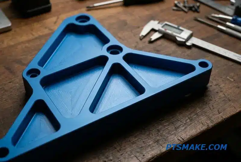
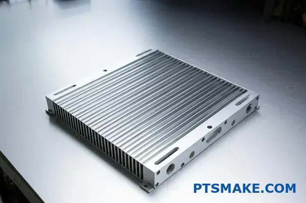
How would you optimize a design for minimum weight of cold plate?
Optimizing a cold plate for minimum weight is a critical task. It requires a holistic approach. It is not just about the plate itself. You must consider the entire system.
Start with Material Choice
The easiest win is material selection. Aluminum is often the best choice over copper for weight-sensitive applications.
| Material | Density (g/cm³) | Thermal Conductivity (W/m·K) |
|---|---|---|
| Aluminum | 2.70 | ~205 |
| Copper | 8.96 | ~400 |
While copper is a better conductor, aluminum offers a great balance. It provides good performance for a fraction of the weight.
Advanced Design Optimization
Beyond materials, we turn to design software. At PTSMAKE, we leverage advanced tools to refine the geometry. This helps us remove every gram of non-essential material.
Topology optimization software is a game-changer. It analyzes a part’s load paths. The software then carves out material from low-stress areas. This creates a strong but lightweight skeletal structure. This process moves beyond simple pocketing. It’s a data-driven method for achieving maximum weight reduction. This intelligent design process, often involving generative design10, helps us create innovative and efficient solutions.
System-Wide Weight Reduction
Optimizing the cold plate is only part of the story. The entire cold plate liquid cooling system contributes to the total weight.
Coolant Volume
Minimizing the coolant in the system is key. Smaller internal channels and shorter tube runs reduce the required fluid volume. Water is heavy, so less is more.
Component Materials
Finally, look at other components. Using lightweight composite materials for tubing and reservoirs can significantly cut overall system weight. Every component matters.
| Optimization Strategy | Impact on Weight | Consideration |
|---|---|---|
| Topology Optimization | High | Requires advanced software and analysis |
| Minimize Coolant | Medium | Balance between volume and flow rate |
| Composite Tubing | Low-Medium | Check for material compatibility |
By combining these strategies, we can create highly efficient and remarkably lightweight cooling solutions for our clients.
Optimizing for minimum weight involves a multi-pronged strategy. It starts with smart material selection like aluminum, uses advanced topology optimization for the plate body, and considers the entire system, including coolant volume and component materials.
What reliability tests are required for a new cold plate design?
A new cold plate design looks great on paper. But will it survive in the real world? This is where validation testing comes in. It is non-negotiable for ensuring reliability and performance.
Core Validation Tests
We focus on key tests that simulate real-life stress. This step confirms the cold plate liquid cooling system can handle pressure, temperature swings, and physical shock. These tests are fundamental.
Below is a quick overview of the essential tests.
| Test Type | Primary Goal |
|---|---|
| Pressure Proof | Detect leaks, ensure structural integrity. |
| Thermal Cycling | Check for fatigue and material failure. |
| Vibration/Shock | Simulate transport and operational stress. |
These checks separate a prototype from a production-ready part.
A Deeper Look at Each Test
Let’s break down why each test is so critical. Every test reveals a different aspect of the cold plate’s durability. It’s about building a complete picture of its long-term reliability.
Pressure Proof Testing
This is a fundamental safety and performance check. We typically subject the cold plate to 1.5 to 2 times its maximum expected operating pressure. This test confirms that all joints, welds, and fittings are perfectly sealed. A leak here means total system failure.
Thermal Cycling
This test mimics the power-on and power-off cycles a device experiences. We repeatedly heat and cool the plate, often thousands of times. This process is crucial for revealing weaknesses in brazed joints or the thermal interface material due to expansion and contraction. We carefully check for signs of material fatigue11 which could lead to failure.
Vibration and Shock Testing
Your product will be shipped and handled. It might also operate in a high-vibration environment, like in automotive or industrial machinery. This testing ensures the cold plate can withstand these physical forces without breaking.
| Test | Common Parameters | Why It Matters |
|---|---|---|
| Corrosion Test | Long-term coolant exposure | Ensures material compatibility, prevents clogs. |
| Pressure Test | 1.5x max operating pressure | Prevents catastrophic leaks in the field. |
| Thermal Cycle | -40°C to 125°C, >1000 cycles | Validates long-term joint and TIM stability. |
In our experience at PTSMAKE, tailoring these test parameters to the specific application is key.
Comprehensive validation—including pressure, thermal, vibration, and corrosion tests—is essential. It proves a new cold plate design is robust and reliable for its environment. This process prevents costly field failures and ensures long-term performance and customer trust.
How do you handle sealing and leak prevention over cold plate lifetime?
Preventing leaks in a cold plate isn’t a one-time task. It is a long-term commitment. A seal must endure years of operation. This includes temperature swings and constant vibration.
The key is designing for the entire lifetime. It is not just for the initial pressure test.
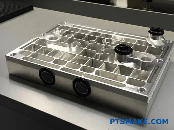
O-Rings: The First Line of Defense
Proper O-ring selection is critical. The material must match the coolant and temperature range. Groove design and compression are equally important for a reliable seal.
| Material | Best For | Temperature Range |
|---|---|---|
| EPDM | Water/Glycol mixtures | -50°C to 150°C |
| Viton (FKM) | Oils, aggressive fluids | -20°C to 200°C |
Thread Sealants
For threaded fittings, always use a quality liquid sealant. It fills microscopic gaps that tape might miss. This ensures a durable, vibration-resistant seal.
Long-term reliability is paramount. While gaskets are common, they introduce risks over time. We must think about the forces a cold plate endures throughout its service life.
The Weakness of Gasketed Designs
Gaskets seem simple. However, they are often the weak point in a system. They are susceptible to failure from thermal cycling. Constant expansion and contraction weakens the seal.
Vibration also takes a toll. It can cause the clamping force on the gasket to loosen. This eventually creates a leak path. Over years, the gasket material itself can degrade. It may lose its elasticity due to a process known as Creep12, especially under constant pressure and temperature.
Why Welded or Brazed Joints Are Superior
For multi-part cold plates, we strongly advocate for permanent joints. Welding or brazing is the best approach for high-reliability cold plate liquid cooling applications.
These methods create a single, solid assembly. This eliminates the gasket as a potential failure point entirely. In our experience at PTSMAKE, this approach provides the highest level of long-term leak prevention.
| Sealing Method | Initial Cost | Long-Term Reliability | Serviceability |
|---|---|---|---|
| Gasket | Low | Moderate | High |
| Brazing | Moderate | Very High | Low |
| Welding | High | Highest | Low |
For ultimate reliability in cold plate liquid cooling, prioritize robust O-ring design for serviceable ports. For permanent assemblies, welded or brazed joints are vastly superior to gaskets, eliminating leak paths and ensuring performance over the product’s entire lifetime.
Get a Quote for Custom Cold Plate Solutions from PTSMAKE
Ready to achieve reliable, high-performance cold plate liquid cooling for your application? Contact PTSMAKE now for a tailored quote—leverage our precision manufacturing expertise, fast prototyping, and trusted B2B service to turn your design into reality. Inquire today and experience worry-free production!

Understand the metallurgical bonding in brazing and why it’s crucial for high-performance thermal management. ↩
Discover how uneven coolant flow can create dangerous hotspots and what to do about it. ↩
Understand how this key metric directly impacts your system’s cooling efficiency and component temperatures. ↩
Learn how fluid viscosity impacts pumping requirements and overall system efficiency. ↩
Learn how this key parameter affects fluid dynamics and cooling efficiency in compact thermal management solutions. ↩
Learn how this complex, repeating structure revolutionizes thermal management in our detailed guide. ↩
Learn how this electrochemical process enhances surface durability and corrosion resistance on metal parts. ↩
Discover how this method targets hotspots with high-velocity fluid for superior cooling performance. ↩
Learn how this simulation technique predicts fluid flow and heat transfer for better designs. ↩
Discover how this AI-powered process explores thousands of design options to find the best solutions. ↩
Learn how repeated stress can impact metal structures and lead to failure over time in thermal management systems. ↩
Learn how this material behavior can compromise seal integrity over time. ↩