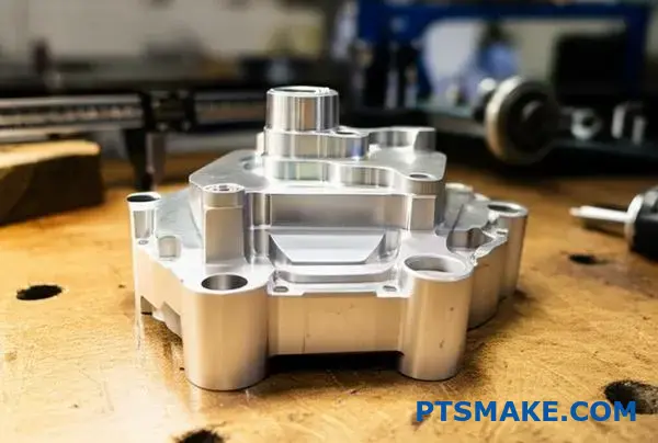
Finding the right sand casting manufacturer can feel overwhelming when your project demands precision and reliability. You’re dealing with complex geometries, tight tolerances, and the constant pressure to deliver quality parts on time and budget.
As a custom sand casting parts manufacturer with over two decades of experience, PTSMAKE specializes in producing high-quality sand cast components for aerospace, automotive, machinery, and industrial applications, delivering precision from prototype to full production.
The sand casting process involves many technical decisions that directly impact your final product quality. I’ve worked with clients who struggled with casting defects, material selection challenges, and quality control issues. This guide covers the essential knowledge you need to make informed decisions about sand casting processes, from understanding different sand types to troubleshooting common defects and optimizing your casting yield.
What are the main categories of sand casting processes?
Sand casting is not a one-size-fits-all process. The key difference lies in the binder system used to hold the sand together. This choice dictates the final part’s quality and cost.
Green Sand Casting
This is the most common and affordable method. It uses a mix of sand, clay, and water. It is ideal for high-volume production of ferrous and non-ferrous metals.
Chemically Bonded Sand Casting
Also known as the no-bake process. It uses a liquid resin that hardens at room temperature. This provides better dimensional accuracy than green sand.
Shell Molding
This process uses a resin-coated sand to form a thin shell mold. It creates parts with excellent surface finish and tight tolerances.
| Process Type | Core Application |
|---|---|
| Green Sand | High-volume, less complex parts |
| Chemically Bonded | Large parts, higher accuracy |
| Shell Molding | Complex shapes, superior finish |
The choice of a sand casting process directly impacts your project’s outcome. It’s a balance of cost, complexity, and desired quality. Over the years at PTSMAKE, we guide clients through this selection daily.
Diving Deeper into Binders
The binder system1 is the heart of the mold. It determines the mold’s strength, surface finish, and how easily the casting can be removed. Each system has its place.
Green Sand’s Simplicity
Green sand is popular because the sand is reusable. This significantly lowers material costs for large production runs. However, it offers less dimensional stability compared to other methods. This can be a challenge for parts requiring high precision.
The Precision of Chemical Bonds
No-bake processes offer superior strength and dimensional control. The chemical reaction creates a rigid mold, perfect for heavy or complex castings where accuracy is key. This is a go-to for many industrial applications we handle.
The Finesse of Shell Molding
For intricate designs and a smooth finish, shell molding excels. The thin mold allows for excellent gas permeability. This reduces defects and often minimizes the need for secondary machining, saving time and money in post-production.
| Feature | Green Sand | Chemically Bonded | Shell Molding |
|---|---|---|---|
| Surface Finish | Fair | Good | Excellent |
| Complexity | Low to Medium | Medium to High | High |
| Tooling Cost | Low | Medium | High |
| Cycle Time | Fast | Slow | Medium |
The main categories of sand casting are defined by their binder systems. Green sand is cost-effective for volume, while chemically bonded and shell molding processes offer higher precision and better finishes for more demanding applications.
What is the classification system for common casting defects?
To solve casting defects, we first need a clear system. Organizing them into groups helps pinpoint the root cause much faster. It avoids guesswork and saves valuable time.
This approach simplifies diagnosis. We can trace the issue back to a specific stage in the casting process.
Here are the four main categories we use:
| Defect Category | Primary Cause Stage |
|---|---|
| Filling-Related | Molten metal filling the mold |
| Shape-Related | Mold and pattern integrity |
| Gas-Related | Trapped gases during casting |
| Solidification-Related | Metal cooling and shrinking |
This structured method is the first step toward consistent, high-quality parts.
Understanding these categories is key to effective problem-solving. Let’s break down each group with common examples. This systematic approach is something we apply daily at PTSMAKE to ensure quality.
Filling-Related Defects
These occur when the molten metal fails to fill the mold cavity completely or smoothly.
| Defect | Common Cause |
|---|---|
| Misrun | Low pouring temperature or slow pouring speed. |
| Cold Shut | Two streams of metal meeting but not fusing. |
Shape-Related Defects
These defects relate to the final geometry of the casting. They often stem from issues with the mold or pattern.
| Defect | Common Cause |
|---|---|
| Shift | Misalignment of the cope and drag sections of the mold. |
| Warpage | Casting distortion due to internal stresses during cooling. |
Gas and Solidification Defects
Gas defects, like porosity, are caused by trapped gases. This is a common challenge in processes like Sand Casting. Solidification defects, such as shrinkage, happen as the metal cools and contracts. These internal flaws are essentially metallurgical discontinuities2 that can compromise the part’s integrity. Identifying whether a void is from gas or shrinkage is critical for finding the right solution.
A logical classification system is essential for efficient diagnosis. Grouping defects by their origin—filling, shape, gas, or solidification—allows engineers to quickly identify and address the root cause, ensuring higher quality and less waste in production.
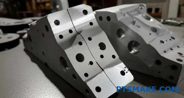
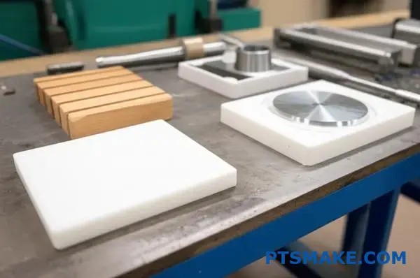
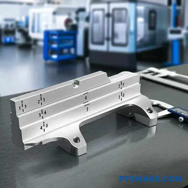
What are the material categories for patterns in sand casting?
Choosing the right pattern material is a critical first step. It directly impacts your project’s cost, quality, and lead time. There is no single "best" material.
The choice depends entirely on your specific needs for the sand casting process.
Let’s break down the three main categories.
Wood Patterns
Wood is perfect for prototypes. It’s also great for one-off parts or very low-volume runs. It’s inexpensive and quick to shape.
Plastic & Polymer Patterns
These offer a step up in durability. They are the go-to for medium-volume production, providing a good balance of cost and longevity.
Metal Patterns
For high-volume, repetitive casting, nothing beats metal. It is the most durable and precise option for long production runs.
| Material | Best Use Case | Durability |
|---|---|---|
| Wood | Prototypes, Low Volume | Low |
| Plastic | Medium Volume | Medium |
| Metal | High Volume | High |
The decision goes far beyond just production volume. At PTSMAKE, we guide clients through the specific trade-offs for their project goals. Each material has unique characteristics to consider.
Wood: Speed vs. Longevity
For simple, single-use patterns, pine is a common choice. For slightly more uses, mahogany offers better durability. However, wood is susceptible to moisture and temperature changes. This can cause warping over time, affecting the final casting’s accuracy. It’s a fast solution, but not a permanent one.
Plastics: The Versatile Middle Ground
Modern polymers, such as polyurethane and epoxy resins, are excellent. They provide much better wear resistance than wood against abrasive sand. The surface finish is also superior, which can reduce post-processing work on the final cast part. They are a reliable choice for consistent quality.
Metals: The Ultimate in Precision
When clients need thousands of identical parts, we recommend metal patterns. Aluminum or cast iron are top choices. They provide the highest dimensional stability3 and can last for over 100,000 cycles. While the initial tooling cost is higher, the cost-per-part drops significantly on large runs. This makes them the most cost-effective solution for mass production.
| Feature | Wood | Plastic/Polymer | Metal |
|---|---|---|---|
| Initial Cost | Low | Medium | High |
| Durability | Low | Medium-High | Very High |
| Surface Finish | Fair | Good | Excellent |
| Lead Time | Short | Medium | Long |
| Best For | < 100 Casts | 100 – 5,000 Casts | > 5,000 Casts |
Your choice of pattern material is a strategic trade-off. Wood offers speed for prototypes. Metal provides ultimate durability for mass production. Plastics present a versatile, balanced solution for most medium-volume sand casting projects, ensuring a good return on investment.
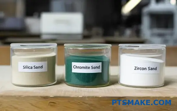
What types of sand are used and why?
When discussing sand casting, the sand’s composition is a critical factor. Not all sands are created equal. The choice directly impacts the final part’s quality.
The Three Main Players
We primarily classify casting sands into three groups. Each has a specific role.
- Silica Sand: The most common and affordable.
- Chromite Sand: A step-up in performance.
- Zircon Sand: The premium choice for specialty jobs.
Here is a quick breakdown of these materials.
| Sand Type | Primary Use | Relative Cost |
|---|---|---|
| Silica | General Ferrous/Non-Ferrous | Low |
| Chromite | Heavy Steel Castings | Medium |
| Zircon | High-Temp Alloys & Precision | High |
Choosing the right one is key to success.
The real difference between these sands lies in their physical properties. These properties determine where each sand excels. Let’s look at what matters most.
Thermal Expansion and Stability
Low thermal expansion is crucial. It prevents mold wall movement and defects like veins or fins on the casting. Silica expands significantly when heated.
This can be a problem for metals with high pouring temperatures. Zircon, on the other hand, has very low thermal expansion. This makes it ideal for high-precision parts made from superalloys, a challenge we often tackle at PTSMAKE.
Thermal Conductivity and Chilling Effect
Thermal conductivity affects how quickly the molten metal cools. Higher conductivity pulls heat away faster.
This "chilling effect" promotes a finer grain structure in the metal. It also helps prevent defects like shrinkage porosity. Chromite offers excellent thermal conductivity. This is why it’s used for thick-section steel castings. It helps ensure the part solidifies properly. Zircon also has a high conductivity and high sintering point4.
| Property | Silica | Chromite | Zircon |
|---|---|---|---|
| Thermal Expansion | High | Medium | Very Low |
| Thermal Conductivity | Low | High | High |
| Refractoriness | Good | Better | Best |
While silica is the workhorse, specialty sands are not just a luxury. They are a necessity for demanding applications where precision and material integrity cannot be compromised.
Choosing the right sand involves balancing properties and cost. While silica is common, specialty sands like chromite and zircon offer superior thermal performance for demanding, high-precision sand casting projects. This ensures higher quality and fewer defects, justifying the investment.
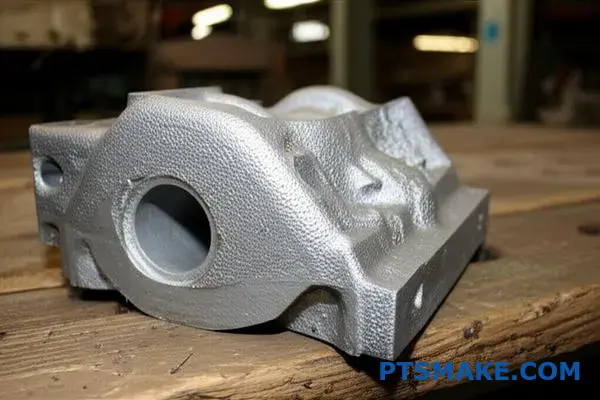
How do cleaning and finishing processes for castings differ?
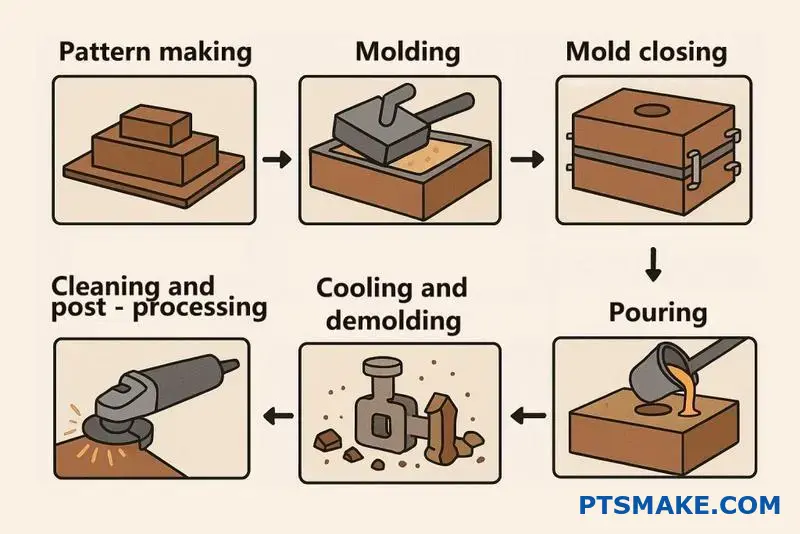
After a casting solidifies and cools, it’s far from ready. It must undergo a series of post-casting processes. This is a highly structured sequence.
This systematic approach is essential. It ensures the final part meets precise engineering specifications. We can break this down into three core stages.
The Post-Casting Sequence
The main phases are Removal, Surface Cleaning, and Finishing. Each stage has a specific goal and method. Following this order is critical for producing a quality component.
| Stage | Primary Goal |
|---|---|
| 1. Removal | Separate casting from the mold |
| 2. Surface Cleaning | Remove surface contaminants |
| 3. Finishing | Achieve final dimensions/properties |
Let’s explore the purpose and sequence of these operations. Think of it as a journey from a rough, raw part to a refined, functional component. Each step adds value and precision.
Stage 1: Removal Operations
This is the initial, aggressive phase. The primary goal is to liberate the casting from its mold and other attachments.
Shakeout and Core Removal
In processes like Sand Casting, shakeout is first. This involves vibrating the mold until the sand breaks away. Afterward, any internal sand cores are carefully removed to reveal the part’s internal passages.
Stage 2: Surface Cleaning
With the casting freed, the focus shifts to its surface.
Shot Blasting
This is a highly effective cleaning method. We propel small metallic shots at high velocity against the casting’s surface. This process removes any remaining sand, scale, or oxides. The result is a clean, uniform surface finish.
Stage 3: Finishing Operations
This final stage is about precision and performance.
Grinding of Gates and Risers
Here, we remove the gates, runners, and risers. These are the channels that allowed molten metal to fill the mold. Grinding or cutting brings the part to its near-net shape.
Heat Treatment
This step modifies the part’s mechanical properties. It involves controlled heating and cooling cycles. This can relieve internal Residual Stress5, increase hardness, or improve strength. It’s a critical step for high-performance applications.
The journey from a rough casting to a finished part is methodical. It involves separating the part, cleaning its surface, and applying finishing touches like grinding and heat treatment. This sequence ensures the component meets all design and performance specifications.
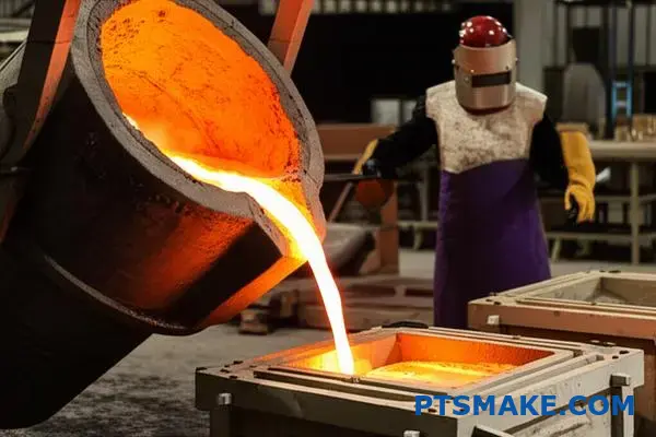
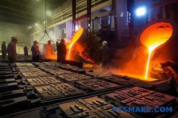
How do you control the pouring process for quality?
A checklist is not just bureaucracy. It is your best defense against inconsistency. For a process as critical as pouring in Sand Casting, a detailed checklist ensures every single pour meets the highest standard. It turns tribal knowledge into a repeatable process.
Pre-Pour Preparations
Before any metal is poured, several checks are vital. These steps set the foundation for a successful cast. They prevent temperature loss and contamination.
| Check Item | Status | Notes |
|---|---|---|
| Ladle Pre-Heated | PASS / FAIL | Target: Cherry-red heat |
| Metal Temperature | PASS / FAIL | Verified with pyrometer |
| Dross Skimmed | PASS / FAIL | Surface must be clean |
Executing the Pour
The action of pouring must be deliberate and controlled. The goal is to fill the mold quickly without introducing defects. A steady hand is key here.
The Importance of Each Checkpoint
A checklist is only effective if the team understands the "why" behind each step. It’s not about just ticking boxes; it’s about active quality control. Overlooking one step can compromise the entire casting.
Temperature and Fluidity
Verifying the metal temperature is non-negotiable. If it’s too cold, the metal won’t fill the mold completely. This leads to misruns. If it’s too hot, it can damage the sand mold and alter the final grain structure.
Preventing Thermal Shock
Pre-heating the ladle might seem minor, but it’s crucial. Pouring molten metal into a cold ladle causes an instant temperature drop. This can lead to premature solidification. It also protects the ladle from thermal shock, extending its life.
Eliminating Contaminants
Dross, the impurities that float on molten metal, is a direct path to defects. Skimming it ensures only clean metal enters the mold. These inclusions create weak spots in the final part.
A steady pour rate helps achieve a consistent fill, minimizing air entrapment and oxide formation. The goal is to establish a gentle, non-turbulent flow. Maintaining this flow, especially when filling the sprue basin, prevents defects. This is where operator skill truly shines, turning a manual process into a precise action. In our experience at PTSMAKE, consistent training on achieving this laminar flow6 dramatically reduces scrap rates.
| Pouring Technique | Outcome |
|---|---|
| Steady & Uninterrupted | Clean casting, no inclusions |
| Intermittent or Slow | Cold shuts, misruns |
| Too Fast or Turbulent | Air entrapment, sand erosion |
A pouring checklist is a foundational tool for quality. It standardizes a critical process, eliminates guesswork, and ensures every casting starts with the best possible chance of meeting specifications, which is a core value at PTSMAKE.
How do you calculate casting yield and improve it?
Understanding casting yield is crucial. It directly impacts your costs and efficiency. The calculation itself is straightforward. It reveals how much molten metal becomes a final product.
The formula is simple:
| Component | Description |
|---|---|
| Weight of Final Casting | The weight of the finished part after removing gates, risers, and runners. |
| Total Weight of Poured Metal | The total weight of all metal poured into the mold. |
Yield is expressed as a percentage. A higher yield means less waste. It’s a key performance indicator for any casting operation.
The Yield Formula
Yield % = (Weight of Final Casting / Total Weight of Poured Metal) x 100%
Improving yield isn’t just about saving metal. It’s about optimizing the entire process. At PTSMAKE, we focus on smart, practical changes that deliver real results. Small adjustments can lead to significant savings.
Optimizing Gates and Risers
The gating system guides molten metal into the mold cavity. Risers act as reservoirs to compensate for volumetric shrinkage7. If these are too large, you are wasting metal. If they are too small, you risk defects.
We use simulation software to model metal flow. This helps us find the optimal size. The goal is to make them as small as possible without compromising part quality. This balance is key.
Improving Mold Layout
How you arrange parts in a mold matters. In processes like Sand Casting, a smarter layout can fit more parts per mold. This increases the ratio of part weight to total metal poured.
Consider this simplified comparison based on past project data:
| Layout Strategy | Parts per Mold | Potential Yield Increase |
|---|---|---|
| Standard Layout | 8 | Baseline |
| Optimized Layout | 10 | ~15-20% |
This approach reduces the material used for runners. It also shortens production cycles, boosting overall efficiency. It’s about working smarter, not just harder.
In short, calculating yield is simple math. Improving it requires engineering expertise. Focus on optimizing your gating system and mold layout for significant gains in efficiency and cost reduction.
Imagine a client shows you a casting. The surface is rough, almost gritty. The diagnosis is metal penetration, a common issue in Sand Casting. This problem demands a swift, methodical response.
My immediate action plan is not a guess. It’s a systematic process we’ve refined. It involves checking four critical variables. This structured approach helps us pinpoint the root cause quickly and efficiently.
Initial Investigation
Key Checkpoints
Our plan starts with the fundamentals of the sand mold itself.
| Step | Focus Area |
|---|---|
| 1 | Sand Compaction |
| 2 | Grain Fineness |
| 3 | Binder Levels |
| 4 | Mold Coating |
This checklist ensures we don’t miss any potential cause.
Developing the Action Plan
A rough surface is unacceptable. We need to restore the part to specification. Here’s how we break down the problem to find a solution. We start with the physical properties of the mold.
Analyzing Mold Density
First, we check sand compaction. If the sand is too loose, molten metal can seep between the grains. This creates the rough finish. We use a mold hardness tester to get precise, repeatable measurements. This eliminates guesswork.
Sand and Binder Adjustments
Next, we look at the sand itself. Using a finer sand grain can create a denser mold surface. This leaves less room for metal to penetrate. However, this can impact gas permeability8, so it’s a careful balance.
We also verify the binder levels. Too little binder results in a weak mold that can’t resist the metal’s pressure. Too much can introduce other gas-related defects. At PTSMAKE, we ensure the sand-to-binder ratio is perfect for the job.
Applying a Protective Barrier
The Final Defense: Refractory Coating
If the issue persists, applying a refractory mold coating is a highly effective solution. This coating acts as a barrier. It prevents any direct contact between the molten metal and the sand mold, ensuring a smooth finish.
| Tactic | Primary Benefit | Consideration |
|---|---|---|
| Increase Compaction | Better mold density | May require equipment changes |
| Use Finer Sand | Smoother surface | Can trap gases |
| Adjust Binder | Stronger mold | Requires precise mixing |
| Apply Coating | Excellent barrier | Adds an extra process step |
Solving metal penetration requires a systematic approach. We analyze sand compaction, grain fineness, binder levels, and consider refractory coatings. This methodical process ensures we deliver the smooth, high-quality surface finish our clients expect.
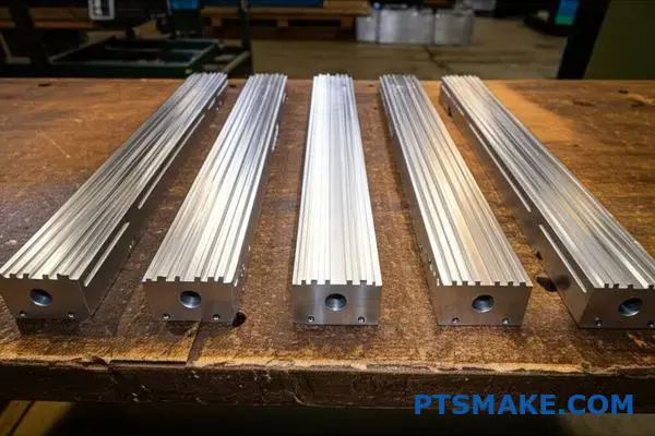
How do you manage casting distortion in a long, thin part?
Managing distortion in long, thin parts is a constant challenge. The primary cause is uneven cooling, which creates internal stress and leads to warpage. It’s a puzzle we solve regularly at PTSMAKE.
Analyzing Stress and Warpage
During cooling, different sections of a part shrink at different rates. Thinner areas cool and contract quickly, while thicker sections remain hot longer. This differential creates a tug-of-war within the material, causing it to bend or twist.
Practical Solutions
We apply several strategies to counteract these forces. These proactive measures are crucial for maintaining dimensional accuracy.
| Solution | Primary Function | Best For |
|---|---|---|
| Reinforcing Ribs | Add structural stiffness | Preventing bending |
| Stress-Relief Bars | Absorb cooling stress | Complex geometries |
| Modified Cooling | Promote uniform shrinkage | All thin parts |
Applying Principles to Challenging Geometries
Controlling distortion requires more than just a single fix. We use a combination of design, process, and thermal management techniques, especially for complex geometries.
Adding Reinforcing Ribs to the Pattern
One of the most effective methods is adding reinforcing ribs. These aren’t part of the final product’s function but serve to strengthen the casting during its vulnerable cooling phase.
We strategically place ribs to counteract bending forces. After the casting has stabilized, these ribs can often be machined away if they are not part of the final design. This is a common practice in producing parts that need to be both lightweight and straight.
Using Stress-Relief Features
In the mold design, we can incorporate features like stress-relief bars or "breakers." These small, strategically placed pieces are designed to deform or break under the strain of cooling.
This controlled failure absorbs the residual stresses9 that would otherwise warp the main part. It’s a clever way to redirect destructive forces. This technique is particularly useful in Sand Casting where mold design offers flexibility.
Modifying the Cooling Process
Controlling the cooling rate is fundamental. Rapid, uncontrolled cooling is the enemy of dimensional stability.
| Cooling Modification | Description | Benefit |
|---|---|---|
| Insulating Blankets | Cover specific areas of the mold to slow heat loss. | Equalizes cooling rates across the part. |
| Controlled Airflow | Use fans or vents to manage the cooling environment. | Prevents drastic temperature differentials. |
| Shakeout Timing | Adjust when the part is removed from the mold. | Allows for gradual, uniform cooling. |
By managing how heat escapes the casting, we ensure the entire part cools and shrinks at a more uniform rate. This significantly reduces the internal stresses that cause distortion.
Managing distortion in long, thin parts involves adding structural support like ribs, using stress-relief features in the mold, and precisely controlling the cooling process. A multi-faceted approach ensures the final part meets its required geometric tolerances.
Develop a quality control plan for a critical casting.
A formal plan turns process knowledge into repeatable success. It’s a roadmap for everyone involved. This document outlines every crucial check.
It ensures consistency from the first casting to the last. Clear rules prevent guesswork and errors.
Key Inspection Checkpoints
We map out specific points for verification. Each stage has defined pass/fail criteria. This is fundamental for critical components.
| Stage | Key Checkpoints |
|---|---|
| Incoming Materials | Sand analysis, metal chemical composition |
| Mold & Core | Dimensional accuracy, integrity, moisture |
| Metal Pouring | Temperature, pouring rate, time |
| Final Casting | Visual, dimensional, NDT |
This structure leaves no room for ambiguity.
Defining Clear Acceptance Criteria
A plan is only as good as its criteria. These standards must be specific, measurable, and objective. Vague goals lead to inconsistent quality.
At PTSMAKE, we link every criterion directly to the part’s function.
Raw Material Standards
For sand casting, the properties of the sand are critical. We define acceptable ranges for grain size and clay content. Metal chemistry is verified against the material specification before it ever enters the furnace.
In-Process Parameter Control
During production, we monitor key variables. Pouring temperature is controlled within a narrow window. This prevents defects like misruns or hot tears. Mold integrity is checked just before closing.
Final Casting Validation
This is the final gate. A combination of tests confirms the part meets all specifications. This includes visual checks, dimensional analysis, and deeper inspection through Metallographic analysis10.
| Validation Method | Purpose | Example Criteria |
|---|---|---|
| Visual Inspection | Surface defects | No visible cracks, porosity, or surface inclusions |
| Dimensional (CMM) | Geometric accuracy | All critical dimensions within ±0.1mm tolerance |
| NDT (X-Ray) | Internal integrity | No internal shrinkage porosity larger than 1mm |
This multi-layered approach ensures reliability.
A formal quality plan requires defining inspection points and measurable acceptance criteria. This systematic process, from raw materials to final validation, is essential for producing consistently reliable and high-quality critical castings.
How would you troubleshoot a mold shift or core shift defect?
A dimensional error is a clear sign of trouble. Often, the cause is a mold or core shift. This creates a mismatch between the two halves of the part.
Troubleshooting this requires a systematic approach. Don’t guess. Instead, follow a clear checklist to find the root cause. This saves time and material.
We will walk through the key checkpoints. We’ll start from the pattern and work our way to the final mold closing. This method is effective for sand casting defects.
Key Inspection Points
| Area to Check | Common Issues |
|---|---|
| Pattern Alignment Pins | Wear, damage, or bending |
| Mold Flasks | Distortion, looseness |
| Core Print Clearances | Too loose or too tight |
| Mold Closing | Uneven or abrupt closing |
A Systematic Diagnostic Approach
When a part’s dimensions are off, panic is not the answer. Precision is. A methodical check is the fastest way to solve the issue. Let’s break down the process step-by-step. In my experience, skipping steps leads to repeated failures.
Inspecting the Pattern and Flasks
First, check the basics. Are the pattern’s alignment pins and bushings worn? Even slight wear can cause a significant shift. Ensure they are straight, clean, and fit snugly.
Next, look at your mold flasks. Flasks can warp over time, especially with heavy use. Check for any distortion or damage that could prevent the mold halves from seating perfectly. When closing the cope and drag11, ensure the alignment is perfect and there are no gaps.
Analyzing Core and Closing Procedures
Now, examine the core print clearances. If the clearance is too large, the core can float or move during pouring. If it’s too tight, the core can be crushed or pushed out of place during closing. This is a delicate balance.
Finally, review the mold closing procedure itself. Is it being done carefully and evenly? Dropping the top half (cope) onto the bottom (drag) can easily shock the core and cause it to shift. A slow, controlled closure is critical for accuracy.
| Component | Troubleshooting Action | Desired Outcome |
|---|---|---|
| Alignment Pins | Measure for wear; check for bends. | Snug fit, perfect alignment. |
| Mold Flasks | Use a straight edge to check for flatness. | No gaps between flasks. |
| Core Prints | Verify dimensions against the drawing. | Core is secure but not crushed. |
| Closing Process | Observe the closing action. | Slow, even, and controlled closure. |
A systematic check of pins, flasks, core clearances, and closing procedures is the most efficient way to diagnose and fix mold shifts. This methodical approach ensures you identify the root cause, preventing costly rework and scrap.
How do you balance cost versus quality in process decisions?
Choosing cheaper materials can seem like an easy win. You see an immediate saving on the purchase order. It looks good on paper.
But this initial saving can be a trap. Let’s consider a real-world example from Sand Casting. A supplier offers sand that is 20% cheaper.
This seems like a fantastic deal. But what are the hidden costs? The real challenge is looking beyond the initial price tag. True cost is more than the material purchase price.
| Material Option | Initial Cost per Ton | Perceived Savings |
|---|---|---|
| Standard Quality Sand | Reference Price | 0% |
| Cheaper Sand | 20% Less | 20% |
This simple table shows the appeal. However, it doesn’t tell the whole story. We need to dig deeper.
The true impact of a material choice reveals itself on the production floor. That cheaper sand might not hold up under pressure. It could lead to a higher rate of defects.
Uncovering the Real Production Cost
In our Sand Casting scenario, the cheaper sand caused more surface imperfections. This increased our defect rate significantly. Initial material savings quickly disappeared. We had to account for scrap and rework.
This is where we analyze the Total Cost of Ownership12. It’s a framework we use at PTSMAKE to guide decisions. It forces us to calculate all costs, not just the upfront ones.
Let’s break down the numbers for producing 100 good parts. Our testing showed the defect rate jumped from 2% to 10% with the cheaper sand.
| Cost Analysis | Standard Sand | Cheaper Sand |
|---|---|---|
| Unit Production Cost | $50 | $48 |
| Defect Rate | 2% | 10% |
| Units to Produce (for 100 good ones) | ~102 | ~111 |
| Total Production Cost | ~$5,100 | ~$5,328 |
As you can see, the cheaper sand actually increased the total cost by over 4%. The initial 20% saving was completely wiped out by waste and rework. Making decisions based on the full picture is crucial.
Choosing cheaper materials without a full analysis is a major risk. The initial savings are often an illusion, erased by increased scrap, rework, and potential delays. A holistic view prevents costly long-term problems.
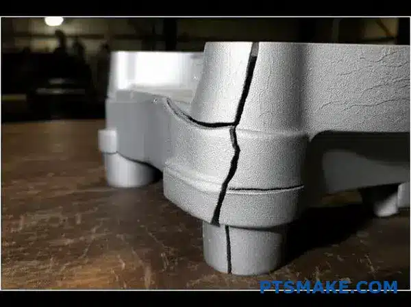
How would you fix a hot tear defect in a casting?
Hot tears are frustrating cracks that appear during casting solidification. They happen when the cooling metal is too weak to resist internal stresses.
This isn’t just a surface-level issue. It points to a deeper problem in your casting design or process.
Understanding the Stress
The root cause is hindered contraction. As the metal cools and shrinks, parts of the mold can block this movement, creating tension. When this tension exceeds the metal’s strength at high temperatures, a tear forms.
Key Areas to Address
To fix this, we must reduce that internal stress. Here are the main areas I focus on.
| Area of Focus | Goal |
|---|---|
| Mold Design | Allow for easier contraction |
| Gating System | Control cooling rate |
| Material Choice | Increase hot strength |
We can systematically eliminate these defects by addressing these points. It ensures a robust final product.
Fixing hot tears requires a multi-faceted approach. We can’t just change one thing and hope for the best. It’s about a systematic reduction of thermal stress throughout the casting as it cools and solidifies.
Improve Core and Mold Collapsibility
The mold itself can prevent the casting from shrinking freely. This is especially true in processes like Sand Casting.
If the core is too strong, it won’t collapse as the metal shrinks around it. This creates immense stress. We often adjust the binder content in sand cores to ensure they weaken and crush at the right moment.
Use Fillets to Reduce Stress
Sharp corners are stress concentration points. During cooling, these areas are highly prone to tearing.
Adding generous fillets or radii at these junctions distributes the stress over a larger area. This simple design change dramatically reduces the risk of cracks. In past projects at PTSMAKE, we’ve found that optimizing fillet radius can be one of the most cost-effective solutions. The hindered contraction13 is less likely to cause failure at a smooth transition than at a sharp angle.
Refine Riser and Gating Design
A well-designed riser and gating system is crucial. It ensures the casting solidifies progressively.
| Design Element | Purpose |
|---|---|
| Risers | Provide a source of molten metal to compensate for shrinkage. |
| Gating | Controls the flow and cooling rate, minimizing hot spots. |
| Chills | Accelerate cooling in thick sections to promote uniform solidification. |
By controlling the cooling sequence, we ensure the casting gains sufficient strength before significant stress builds up. This prevents tears from forming in the first place.
Hot tears are stress fractures caused by hindered contraction during solidification. Fixing them involves improving mold collapsibility, adding fillets to reduce stress concentration, and refining the riser and gating design for controlled cooling.
Partner with PTSMAKE for Your Next Sand Casting Project
Ready for consistent excellence in your sand casting parts? Contact PTSMAKE today for a fast, competitive quote and experience top-tier quality, reliability, and proactive service from prototype to production. Send your inquiry now—discover how we exceed expectations for B2B manufacturing leaders like you!

Discover how binder selection affects part quality, cost, and lead times in our detailed guide. ↩
Learn how these internal flaws form and how to detect them for better quality control. ↩
Learn how this property ensures your cast parts remain true to the original design specifications over time. ↩
Understand how this property impacts mold integrity and casting surface finish at high temperatures. ↩
Learn how internal stresses affect part performance and why managing them is critical for reliability. ↩
Learn how controlling fluid dynamics is key to preventing common casting defects and improving part integrity. ↩
Understand how metal contraction during cooling impacts final part quality. ↩
Learn how this critical property impacts casting quality and helps prevent defects. ↩
Learn how these internal forces impact part integrity and long-term performance. ↩
Learn how this microscopic examination reveals a casting’s internal structure and predicts its performance. ↩
Learn the foundational terms of sand casting to better understand the molding process. ↩
Learn how to calculate the true cost of a purchase beyond its initial price tag for better decisions. ↩
Learn more about the metallurgical principles behind casting stress and solidification. ↩