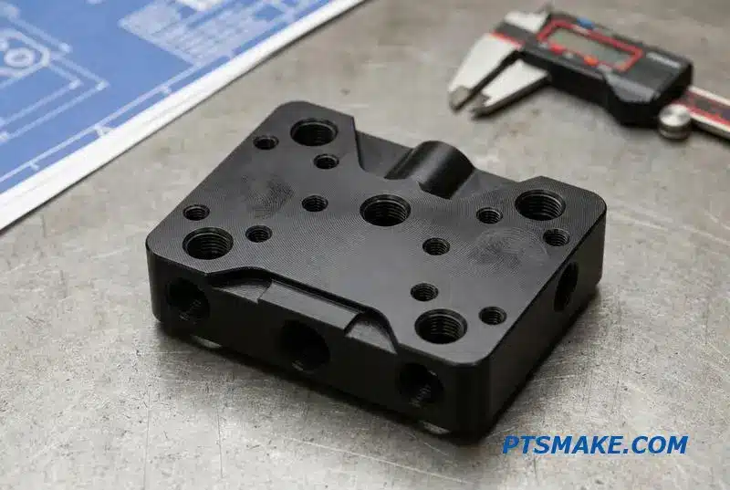
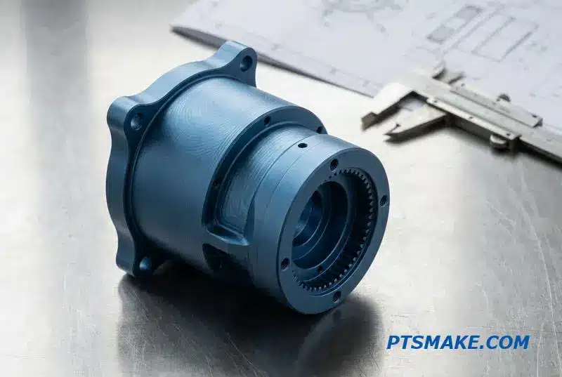
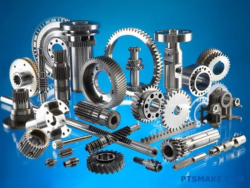
You’re dealing with gear precision issues that cost your projects time and money. When your gears fail to meet specs, your entire system suffers from vibration, noise, and premature wear.
Precision gears require transmission error under 5 arc-seconds, pitch deviations within ±2 microns, and runout less than 10 microns. These parameters directly impact system performance beyond basic dimensional tolerances.
I’ve worked with engineers who struggled with gear selection, thermal management, and achieving zero-backlash designs. This guide covers the technical fundamentals you need, from material selection and failure analysis to advanced manufacturing methods and real-world applications in robotics and aerospace systems.
What fundamentally defines a ‘precision’ gear?
When we talk about ‘precision’ gears, many think only of tight tolerances. But that’s just a small part of the story. True precision goes much deeper.
It’s about how the gear performs in motion. Factors like transmission error, pitch deviation, and runout are the real differentiators. These elements define a gear’s smoothness and reliability.
| Feature | Standard Gear | Precision Gear |
|---|---|---|
| Focus | Dimensional Accuracy | Dynamic Performance |
| Key Metrics | Tolerances | Transmission Error, Runout |
| Outcome | Functional Fit | Smooth, Quiet Operation |
Understanding these is key to high-performance systems.
Let’s break down these critical factors. They are what separate a good gear from a great one. These details are crucial for demanding applications.
The True Meaning of Gear Precision
Beyond a Simple Fit
A gear can meet all its dimensional specs on paper. However, it might still create noise and vibration in a system. This is where dynamic performance metrics become essential. They measure how a gear actually behaves under load and in motion.
Understanding Key Deviations
We focus on several key metrics. Transmission Error1 is a crucial one. It measures the deviation from perfectly uniform rotational motion. Even tiny errors can cause significant vibration and noise, especially at high speeds.
Pitch deviation and runout are also vital. They affect how smoothly teeth engage and disengage. Poor control here leads to uneven load distribution across the teeth. This can cause premature wear and failure.
In past projects at PTSMAKE, we’ve seen systems fail not from bad design, but from overlooking these gear metrics. The table below shows the impact.
| Deviation | Primary Impact | Secondary Effect |
|---|---|---|
| Transmission Error | Noise & Vibration | Reduced System Efficiency |
| Pitch Deviation | Uneven Load | Accelerated Tooth Wear |
| Runout | Unbalanced Rotation | Bearing & Shaft Stress |
These aren’t just numbers; they directly influence the lifespan and reliability of your entire assembly.
In short, defining precision gears requires looking beyond static measurements. True precision is measured by dynamic performance, where factors like transmission error and pitch deviation determine a system’s reliability, noise level, and overall lifespan.
What are the primary material properties for precision gears?
When selecting a material for precision gears, three properties are non-negotiable. Hardness, toughness, and dimensional stability form the core triangle of performance.
Hardness directly fights wear and tear. Toughness absorbs shock loads, preventing catastrophic failure. And dimensional stability ensures the gear holds its shape.
This maintains accuracy under heat and stress. Neglecting any one of these can compromise the entire system.
Key Properties at a Glance
| Property | Primary Function |
|---|---|
| Hardness | Resists surface wear and abrasion |
| Toughness | Absorbs impact and shock loads |
| Dimensional Stability | Maintains accuracy under stress |
Hardness for Wear Resistance
Hardness is critical for a gear’s lifespan. It is the material’s ability to resist surface indentation and abrasion. Harder gear teeth wear down much slower, maintaining their precise profile for longer.
This is especially important in high-cycle applications. We often specify materials with a high Rockwell hardness (HRC) rating for this reason. However, extreme hardness can lead to brittleness, creating a delicate balancing act.
Toughness for Impact Loads
Toughness is a material’s capacity to absorb energy and deform without fracturing. This is vital for gears that experience sudden starts, stops, or shock loading.
A tough material prevents teeth from chipping or breaking off under impact. In our experience at PTSMAKE, a lack of toughness is a common cause of premature gear failure, especially in demanding machinery. The study of Tribology2 helps us understand these failure modes.
Dimensional Stability for Accuracy
Precision gears must maintain their exact dimensions. They operate under varying loads and temperatures. Dimensional stability ensures the material doesn’t expand, contract, or warp excessively.
Materials with a low coefficient of thermal expansion (CTE) are preferred. This guarantees consistent meshing and backlash, which is essential for the accuracy of any precision gear system.
| Material Type | Hardness | Toughness | Stability |
|---|---|---|---|
| Hardened Steel | High | Medium | High |
| Stainless Steel | Medium | High | High |
| Engineering Plastic | Low | High | Medium |
| Bronze | Low | Medium | High |
The ideal material balances hardness for wear resistance, toughness to handle impact, and dimensional stability to maintain precision. Overlooking one property for another often leads to compromised performance and a shorter operational lifespan for the gears.
What are the fundamental failure modes of precision gears?
Understanding how precision gears fail is key. We mainly see three common modes. These are tooth bending fatigue, surface fatigue, and wear. Each gives us clues about the operating conditions.
Tooth Bending Fatigue
This happens when a gear tooth breaks off at its base. Repeated loading causes a crack to form and grow. It’s a critical failure that can stop a machine instantly.
Surface Contact Fatigue (Pitting)
Pitting creates small craters on the tooth surface. This is caused by high contact stress during meshing. It starts with tiny cracks below the surface that grow and break out.
Wear
Wear is the slow loss of material from the gear surface. It can be adhesive (scuffing) or abrasive (scratching). Both degrade gear accuracy over time.
| Failure Mode | Primary Cause |
|---|---|
| Bending Fatigue | Excessive cyclic bending stress |
| Pitting | High surface contact stress |
| Wear | Lubrication failure or contamination |
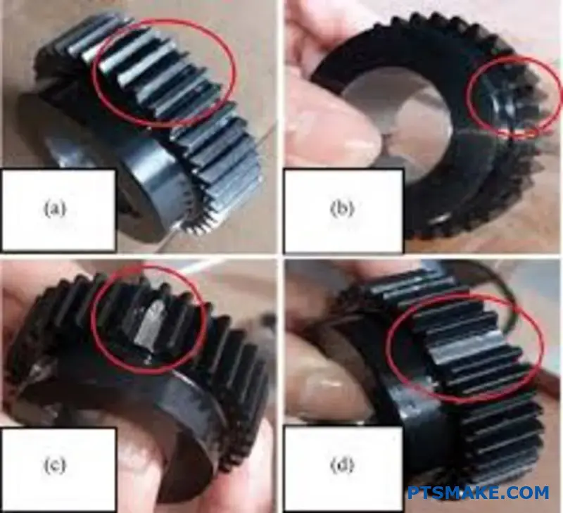
Let’s dive deeper into how these failures occur. Recognizing the specific mechanism helps us at PTSMAKE prevent them in future designs. Each failure mode leaves a distinct visual signature on the gear.
Understanding the Mechanisms
Tooth Bending Fatigue
The mechanism is straightforward. Each time teeth mesh, the load bends the tooth. This repeated bending initiates a tiny crack at the root, where stress is highest. The crack grows with each cycle until the tooth fractures. The final fracture surface often shows "beach marks" from the crack’s slow growth.
Surface Contact Fatigue (Pitting)
Here, the failure is on the tooth surface. The immense pressure at the contact point creates high subsurface stress. After many cycles, this stress leads to the formation of subsurface cracks. These cracks grow towards the surface, eventually causing a piece of material to break away, leaving a pit. The high stress at the contact point, often analyzed using principles of Hertzian contact stress3, is the root cause.
Adhesive and Abrasive Wear
Adhesive wear, or scuffing, happens when the lubricant film breaks down. This allows direct metal-to-metal contact, causing microscopic welds that are instantly torn apart. This smears material across the surface. Abrasive wear is simpler; hard contaminant particles in the lubricant act like sandpaper, grinding away the gear surface.
| Failure Type | Visual Indicator |
|---|---|
| Bending Fatigue | A crack at the tooth root, leading to a complete fracture. |
| Pitting | Small craters or pits on the tooth contact surface. |
| Adhesive Wear | Scuffed, smeared, or galled surface appearance. |
| Abrasive Wear | Scratches or fine grooves along the sliding direction. |
In summary, bending fatigue cracks the tooth root, surface fatigue creates pits, and wear removes material through scuffing or abrasion. Identifying these visual cues is crucial for accurate failure analysis and preventing future issues.
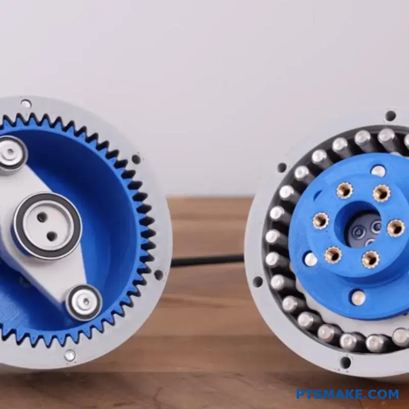
What are the structures of common zero-backlash gears?
Understanding zero-backlash mechanisms is key to achieving true precision. These are not single gears but clever systems designed to eliminate play. Each approach has a unique way of maintaining constant tooth contact.
Split Gears with Springs
This is a common mechanical solution. One gear is split into two thin sections. Springs push these sections apart rotationally. This forces the teeth of each section against opposite sides of the mating gear’s teeth, removing any gap.
Dual-Path and Preloaded Systems
Other methods use preload to eliminate backlash. They create an internal force to keep gear teeth engaged.
| Mechanism Type | Core Principle |
|---|---|
| Dual-Path Gearbox | Two parallel gear trains are preloaded against each other. |
| Electrically Preloaded | A motor applies a constant torque to remove slack. |
These designs are crucial for high-performance applications.
The choice of mechanism deeply impacts performance. At PTSMAKE, we guide clients through these options to match their specific needs for accuracy and load capacity.
A Closer Look at Split Gears
The beauty of the split gear is its simplicity. The spring constantly adjusts for wear over the gear’s life. This makes it a reliable choice for many applications. However, the spring force can add friction. This might slightly reduce efficiency.
Understanding Dual-Path Gearboxes
Dual-path systems offer higher torque capacity. By splitting the load between two gear trains, they can handle more demanding tasks. The preloading is typically set during assembly. This makes them rigid and very precise. This rigidity minimizes mechanical hysteresis4.
The Role of Electrical Preloading
Electrically preloaded systems are dynamic. They use a secondary motor to apply a controlled opposing torque. This actively removes backlash in real-time. This method offers incredible precision. It is ideal for robotics and CNC machines where direction changes rapidly.
Selecting the right structure for precision gears is critical. Based on our tests, the best choice depends on the application’s specific needs.
| Feature | Split Gear | Dual-Path | Electrical Preload |
|---|---|---|---|
| Complexity | Low | Medium | High |
| Cost | Low | Medium | High |
| Best For | Instruments | Heavy Loads | Dynamic Systems |
Each zero-backlash mechanism, from spring-loaded split gears to dynamic electrical preloading, offers a unique solution. The right choice depends on balancing complexity, cost, and the specific precision and torque requirements of the application.
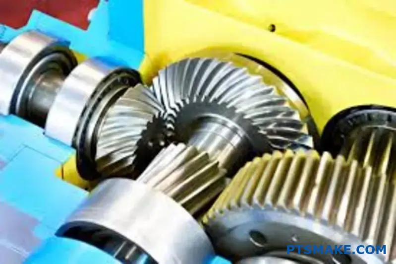
How do harmonic and cycloidal drives achieve high precision?
Harmonic and cycloidal drives are masters of precision. Both offer high gear ratios and near-zero backlash. However, they achieve this through very different mechanical principles.
Harmonic drives use an elegant concept of elastic deformation. They rely on a flexible spline engaging with a rigid circular spline.
Cycloidal drives, in contrast, use a more rugged design. They are built around eccentric rolling motion with discs and pins. Understanding these core differences is key to choosing the right one for your application.
Key Structural Comparison
| Feature | Harmonic Drive | Cycloidal Drive |
|---|---|---|
| Core Principle | Elastic Deformation | Eccentric Rolling Motion |
| Key Components | Flexspline, Wave Generator | Cycloidal Disc, Rollers, Pins |
| Torque Capacity | Moderate | Very High |
| Shock Load | Lower Resistance | Excellent Resistance |
These designs define their ideal uses.
When we discuss high-precision motion control, these two drive types are often the top contenders. In projects at PTSMAKE, we’ve machined critical components for both, and the level of required accuracy is astounding. The choice between them isn’t about which is better, but which is more suitable.
Principle of Operation Explained
Harmonic Drive Mechanics
A harmonic drive has three main parts. A wave generator, which is an elliptical bearing, is placed inside a flexible cup called a flexspline.
The flexspline has external teeth. It is then placed inside a rigid outer ring called the circular spline.
As the wave generator rotates, it deforms the flexspline into an ellipse. This causes its teeth to engage with the circular spline’s teeth at two opposite points. This continuous engagement delivers smooth, high-ratio motion.
Cycloidal Drive Mechanics
A cycloidal drive operates using an input shaft connected to an eccentric bearing. This bearing drives a cycloidal disc.
The disc has a unique curved profile that engages with stationary outer pins or rollers. This design is based on a hypotrochoid5 curve, ensuring multiple teeth are always in contact. This continuous contact eliminates backlash and allows for high shock load capacity, making these Precision Gears incredibly robust.
Application Suitability
| Application Type | Best Fit | Reason |
|---|---|---|
| Robotics (Small/Medium) | Harmonic | Compact, lightweight, low inertia |
| Industrial Automation | Both | Depends on load and speed requirements |
| Heavy Machinery | Cycloidal | High torque and shock load capacity |
| Aerospace Actuators | Harmonic | High precision in a small package |
Harmonic drives excel in applications requiring compact, lightweight precision like robotics. Cycloidal drives are powerhouses, perfect for heavy industrial machinery where torque and durability are paramount. Your final choice depends on balancing load, size, and dynamic performance requirements.
What are the methods for inspecting precision gears?
When inspecting precision gears, we primarily use two approaches. These are analytical inspection and functional inspection. Each method serves a distinct and vital purpose in quality control.
Analytical vs. Functional
Analytical inspection is like a detailed diagnostic. It meticulously measures individual geometric parameters of the gear.
Functional inspection, on the other hand, is a performance test. It checks how the gear meshes and operates as a whole.
| Inspection Type | Main Goal | Typical Measurement |
|---|---|---|
| Analytical | Diagnose Specific Errors | Profile, Lead, Pitch |
| Functional | Assess Overall Performance | Composite Error |
Understanding this difference is key to effective gear quality control.
A Closer Look at Analytical Inspection
Analytical inspection uses high-precision equipment. Coordinate Measuring Machines (CMMs) are a common choice for this task. They can isolate and measure individual gear tooth features with incredible accuracy.
This method provides detailed data on:
- Tooth Profile: The shape of the tooth from its root to its tip.
- Lead: The alignment of the tooth across the gear face.
- Pitch: The distance between adjacent teeth.
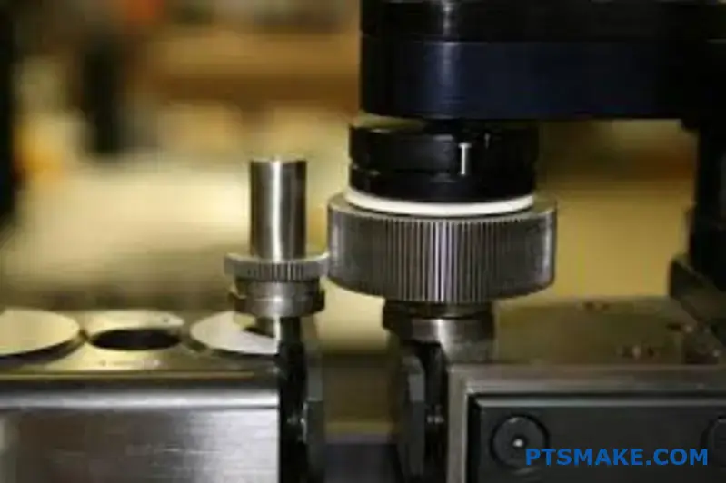
At PTSMAKE, we use this data to pinpoint any deviation from the design. It allows us to refine our CNC machining process and ensure every gear meets exact specifications. This is essential for troubleshooting and process control.
The Role of Functional Inspection
Functional inspection simulates real-world operation. The most common method uses a double flank rolling checker. This tool meshes the gear being tested with a high-precision master gear.
As the gears roll together, the device measures the variation in their center distance. This holistic measurement gives a single value representing the composite error6. It captures the cumulative effect of all individual tooth errors. It is an excellent way to quickly verify the overall smoothness and operational quality of a gear.
| Method | Best Use Case | Key Takeaway |
|---|---|---|
| Analytical | Root Cause Analysis | Specific dimensional data |
| Functional | Production Quality Check | Pass/Fail on mesh quality |
Analytical inspection dissects a gear’s geometry to find specific faults. In contrast, functional inspection provides a quick, practical assessment of how well the gear will perform. Choosing the right method is crucial for ensuring the reliability of precision gears.
How do housing and bearing arrangements affect gear precision?
The housing and bearings are not just support structures. They are active players in your system. Their design directly controls the final precision of your gears.
A system’s accuracy is only as good as its foundation.
The Role of Housing Stiffness
A rigid housing is non-negotiable for high precision. Any flex under operational load will misalign the shafts. This ruins the gear mesh quality, leading to noise and wear.
Bearing Selection and Mounting
The choice of bearings and how they are mounted is equally critical. Every component contributes to maintaining the precise positioning of the shafts.
| Component | Direct Influence On |
|---|---|
| Housing Stiffness | Shaft Alignment Under Load |
| Bearing Arrangement | Rotational Accuracy |
| Mounting Precision | Initial Gear Mesh |
The Foundation: Housing Stiffness
Think of the housing as the bedrock for your gear system. If it deforms, even slightly, the distance between gear centers changes. This shift directly degrades the contact pattern on the gear teeth.
In past projects at PTSMAKE, we’ve seen rigid housings significantly reduce vibration and extend the life of precision gears. A stiff housing ensures that the designed gear geometry is maintained under real-world forces.
A Closer Look at Bearings
The type of bearing you choose dictates how loads are managed. Each has its own strengths and is suited for different applications.
Angular Contact vs. Deep Groove
Deep groove ball bearings are a common choice for their versatility. However, for higher precision, angular contact bearings are often superior. They offer greater stiffness and can handle combined loads more effectively. Applying the correct [preload](https://preload.com/)[^7] is crucial for maximizing their performance.
This is especially true in high-speed applications where controlling shaft movement is key.
| Bearing Type | Primary Benefit | Common Application |
|---|---|---|
| Deep Groove Ball | Cost-Effective, Versatile | General Machinery |
| Angular Contact | High Rigidity and Speed | CNC Spindles, Gearboxes |
| Tapered Roller | High Load Capacity | Automotive Transmissions |
Ultimately, housing stiffness, bearing selection, and mounting precision form a critical trio. They work together to maintain shaft alignment. Getting any of these elements wrong will directly compromise the quality and lifespan of your gear assembly.
How to select the right gear type for an application?
Choosing the right gear can feel overwhelming. I break it down into a simple, logical process. This method helps you focus on what truly matters for your application’s success.
Step 1: Define Core Requirements
First, list your non-negotiable performance needs. What are the operational speed and torque? What level of precision is essential for the task?
Answering these initial questions narrows your options significantly.
| Requirement | Key Question |
|---|---|
| Speed (RPM) | Will the gear operate at high, medium, or low speeds? |
| Torque (Nm) | How much rotational force must the gear transmit? |
| Precision | How critical is positional accuracy for the application? |
Step 2: Evaluate Constraints
Now, think about the physical and operational limits. This includes the available space, budget, and acceptable noise level for the environment. These constraints often drive the final decision.
The real challenge is balancing these competing factors. High performance often conflicts with strict constraints like cost or size. This is where making smart trade-offs is crucial.
The Precision vs. Cost Balance
High-precision gears deliver superior accuracy by minimizing errors. This is vital in fields like automation and medical devices. However, achieving tight tolerances increases manufacturing complexity and cost.
In robotics, minimizing lost motion, or backlash7, is critical for accuracy. This directly impacts the performance of precision gears. At PTSMAKE, we often guide clients through this balancing act.
We help them find the sweet spot. This ensures the gear meets performance specs without inflating the project budget unnecessarily.
A Practical Decision Matrix
Based on our project experience, a simple matrix can guide your choice. It helps visualize how different gear types stack up against common requirements.
| Gear Type | Speed | Torque | Precision | Noise | Cost |
|---|---|---|---|---|---|
| Spur | Moderate | Moderate | Medium | High | Low |
| Helical | High | High | High | Low | Medium |
| Bevel | Moderate | Moderate | Medium | Medium | Medium |
| Worm | Low | High | High | Very Low | High |
This framework provides a solid starting point. It helps you systematically compare the most viable options for your specific design needs.
Following a structured process helps balance performance needs like speed and torque against constraints like cost and noise. This methodical approach ensures you select the optimal gear type for your application.
How to perform a basic gear strength and life calculation?
Following a standard simplifies gear analysis. At PTSMAKE, we often reference AGMA 2001. It provides a clear path for calculations.
Bending and Contact Stress
First, you calculate the fundamental stresses. Bending stress relates to tooth fracture. Contact stress relates to surface wear. These initial numbers are a baseline. They don’t yet account for real-world conditions.
The Role of Modification Factors
Next, you apply various modification factors. These adjust your baseline for operational life estimation. Think of them as reality checks for your design.
A Deeper Look at Modification Factors
The AGMA standard is comprehensive. It guides you in refining initial stress values. This process turns a simple calculation into a reliable prediction. These factors account for variables that impact gear performance.
Modification factors are crucial. They bridge the gap between theory and reality. For example, the dynamic factor considers speed and manufacturing accuracy. High-quality manufacturing of Precision Gears directly improves this factor.
Another key is the load distribution factor. It accounts for how the load is shared across the tooth face. Misalignment or shaft deflection can concentrate stress. Proper design and assembly are vital here. In our past projects, we have seen how small misalignments can drastically reduce gear life.
Key Modification Factors
| Factor | Purpose |
|---|---|
| Dynamic Factor (Kv) | Accounts for inaccuracies in tooth profile and speed. |
| Size Factor (Ks) | Considers material properties based on gear size. |
| Load Distribution (Km) | Adjusts for uneven load across the face width. |
| Surface Condition (Cf) | Reflects the impact of surface finish on Pitting Resistance8. |
These adjustments are essential for accurate life prediction. They ensure the gear not only fits but also survives its intended application.
The AGMA 2001 standard provides a structured method. It helps you move from basic stress numbers to a realistic operational life estimate by applying critical modification factors. This ensures a robust and reliable gear design.
How to specify the optimal backlash for a system?
Determining the right backlash isn’t guesswork. It’s about creating a "backlash budget." This systematic approach accounts for all factors that consume the clearance between gear teeth.
Key Budget Inputs
We must consider every variable that can affect the gear mesh. This ensures the system operates reliably under all conditions.
| Factor | Description |
|---|---|
| Thermal Effects | Material expansion and contraction with temperature. |
| Tolerances | Variations from the manufacturing process. |
| Lubrication | The space required for the lubricant film. |
| Lost Motion | The maximum play the application can tolerate. |
This methodical process removes uncertainty. It leads to a specification grounded in your system’s reality.

Building Your Backlash Budget
A detailed budget prevents operational failures. Each component of the budget must be carefully calculated and summed up. This total must remain below your system’s maximum allowable lost motion.
Thermal Expansion
Materials change size with temperature. A system operating in a wide temperature range needs more backlash. We calculate this using the material’s expansion coefficient and the expected temperature delta. This prevents binding when components get hot.
Manufacturing Tolerances
No part is perfect. Tolerances on gear teeth, shaft diameters, and bearing positions all add up. This cumulative effect, or tolerance stack-up9, directly reduces the designed backlash. Working with a partner like PTSMAKE ensures these tolerances for precision gears are tightly controlled.
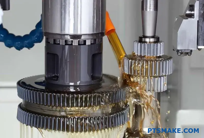
Lubrication Requirements
Lubricant isn’t just for reducing friction. It forms a physical film between teeth. This film requires space. The budget must account for the minimum thickness of this film to ensure proper lubrication and prevent premature wear.
We often use a simple formula to combine these factors.
| Budget Component | Calculation Example (Angular) |
|---|---|
| Thermal Expansion | 0.005° |
| Tolerance Stack-up | 0.010° |
| Lubrication Film | 0.002° |
| Total Required Backlash | 0.017° |
This calculated total must be less than the maximum lost motion your application can handle.
Creating a backlash budget is a critical step. It involves quantifying the effects of thermal expansion, manufacturing tolerances, and lubrication. This total required clearance must then be checked against the system’s maximum allowable lost motion to ensure performance.
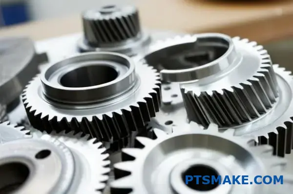
How to choose between hobbing, shaping, and grinding?
Choosing the right gear manufacturing process is critical. It impacts your final product’s performance, cost, and lead time. The decision hinges on three key factors.
These are your gear’s design, the required precision, and your production volume. Each method excels in different areas.
Quick Selection Guide
Here is a simple breakdown to guide your initial thoughts. It helps match the process to your primary need.
| Process | Best For | Key Advantage |
|---|---|---|
| Hobbing | High-volume external gears | Speed and cost-efficiency |
| Shaping | Internal gears & complex features | Versatility in geometry |
| Grinding | Ultra-high precision finishing | Superior accuracy and surface finish |
This table provides a starting point for making an informed choice.
Making the optimal choice requires a deeper look. In our projects at PTSMAKE, we guide clients through these specifics to ensure the best outcome for their application. The wrong choice can lead to unnecessary costs or part failure.
Detailed Process Comparison
Let’s break down the decision based on critical project requirements. This will help you understand the nuances of each method.
Based on Gear Type
Your gear’s physical design is the first filter. Hobbing is the go-to for external spur and helical gears. It’s fast and highly efficient for these common types.
However, if you need internal gears or gears with shoulder interference, shaping is the solution. Its reciprocating cutting action can access areas hobbing cutters cannot.
Based on Required Accuracy
For most industrial applications, hobbing and shaping provide adequate precision. They produce good quality gears suitable for many machines.
But for high-performance systems like aerospace or robotics, grinding is essential. It’s a finishing process that corrects tiny distortions in the tooth’s involute profile10. This step produces top-tier Precision Gears.
Based on Production Volume
For mass production, hobbing is unmatched in speed and cost-effectiveness. It’s ideal for large batches of identical gears.
Shaping is generally slower, making it better suited for smaller runs or prototypes. Grinding is the slowest and most expensive. It is used only when the highest precision justifies the added cost, regardless of volume.
Your final decision balances gear geometry, precision needs, and production scale. Hobbing is for high-volume external gears, shaping handles complex internal features, and grinding delivers the ultimate finishing touch for critical applications.
Design a gear drive for a high-precision robotic joint.
Let’s explore a practical case study. A client required a gear drive for a surgical robot’s wrist joint. The primary goals were absolute precision and smooth motion. This presented three core engineering challenges we had to solve.
Zero-Backlash Requirement
For surgical precision, any "play" or backlash in the joint is unacceptable. The gear system must translate motor movement to the joint with perfect fidelity.
High Stiffness Mandate
The joint must resist deflection when external forces are applied. High stiffness ensures the robot arm remains steady and on its intended path.
Low Inertia Goal
To allow for quick, responsive movements, the drive components must be lightweight. Low inertia enables rapid acceleration and deceleration without overshooting.
Our initial design targets were clear.
| Parameter | Target Value | Rationale |
|---|---|---|
| Backlash | < 1 arc-minute | Guarantees positional accuracy |
| Stiffness | > 150 Nm/arc-min | Prevents deflection under load |
| Inertia | < 0.005 kg·m² | Enables fast, reactive motion |
Justifying the Harmonic Drive Selection
After evaluating options like planetary and cycloidal gears, we chose a harmonic drive. Its unique operating principle was perfectly suited to the project’s demanding requirements.
The harmonic drive uses an elliptical wave generator that deforms a flexible gear cup, the "flexspline." This engages teeth with a rigid outer ring, the "circular spline," in a continuous, rolling motion.
This design inherently eliminates backlash. The flexspline is always preloaded against the circular spline, leaving no room for play.
This continuous engagement across a large number of teeth also results in exceptional torsional stiffness11. It provides a much more rigid connection compared to traditional gears where only a few teeth mesh at once.
Furthermore, its compact, lightweight nature offers a high gear ratio in a small package, minimizing inertia. This makes it ideal for dynamic robotic applications. At PTSMAKE, we frequently machine the complex components for such systems, ensuring the tight tolerances required.
Calculating Key Parameters
With the type selected, we defined the key performance parameters. These calculations confirmed the harmonic drive’s suitability for the application.
| Parameter | Calculation Method | Result |
|---|---|---|
| Gear Ratio | Based on tooth count difference | 100:1 |
| Peak Torque | Motor Torque × Ratio × Efficiency | 55 Nm |
| Avg. Lifespan | Based on load profile & L10 rating | > 25,000 hours |
In this case study, we defined the robotic joint’s critical needs. The harmonic drive was chosen for its zero-backlash and high stiffness. We then outlined the core calculations to validate our design and ensure long-term performance.
How to manage thermal expansion in a tight-clearance gearbox?
Managing thermal expansion requires practical engineering. It’s not about eliminating growth, but controlling it. The right approach ensures reliability.
Material Selection is Key
Choosing materials with compatible expansion rates is crucial. When a gear and its housing expand at similar rates, clearance remains stable. This is vital for high-performance Precision Gears.
| Material | CTE (ppm/°C) | Notes |
|---|---|---|
| Steel | ~12 | Common for gears |
| Aluminum | ~23 | Common for housings |
| Titanium | ~8.6 | High strength, low expansion |
Setting Cold Backlash
We must calculate and set the "cold backlash" correctly. This is the gear clearance at ambient temperature. It allows for expansion when the gearbox heats up during operation.
A proactive strategy involves more than just good design. It requires a deep understanding of how materials behave under thermal stress. This is where precise calculations and system-level thinking come into play.
Calculating Thermal Growth
We don’t guess how much a part will grow. We calculate it. The change in size depends on the material’s properties and the temperature change. In past projects at PTSMAKE, this calculation has been the key to success. Some advanced composites exhibit anisotropic12 behavior, complicating calculations further.
A Practical Example
Consider a steel gear inside an aluminum housing. Aluminum expands nearly twice as much as steel for every degree of temperature increase. This difference must be precisely accounted for in the initial design clearances to prevent binding.
The Role of Cooling Systems
For high-load applications, active cooling is essential. It removes heat and maintains a stable operating temperature. This directly limits the total thermal expansion. Different systems offer various levels of performance and complexity.
| Cooling Method | Effectiveness | Typical Use Case |
|---|---|---|
| Oil Circulation | High | High-torque industrial gearboxes |
| Air Cooling (Fans) | Moderate | Enclosed electronic devices |
| Heat Sinks | Low to Moderate | Low-power motor housings |
Effective management combines smart material choices, precise cold backlash calculations, and, when needed, active cooling systems. This integrated approach is fundamental to creating reliable, tight-clearance gearboxes that perform under thermal stress.
What are the next-generation trends in precision gear technology?
The future of precision gears is exciting. We are moving beyond just cutting metal. New technologies are reshaping what’s possible.
This evolution focuses on creating smarter, stronger, and more complex components. It’s a major leap forward for industries that rely on high performance.
Key Innovations on the Horizon
Additive Manufacturing
3D printing allows for internal cooling channels and lightweight designs. This was impossible with traditional CNC machining alone.
Smart Technology
Sensors embedded within gears can now predict failures. This shifts maintenance from reactive to proactive, saving costs.
| Technology Trend | Primary Impact | Industry Benefit |
|---|---|---|
| Additive Manufacturing | Complex Geometries | Lighter, more efficient parts |
| Super-Hard Materials | Increased Durability | Longer operational life |
| Smart Sensors | Predictive Maintenance | Reduced downtime |
Diving Deeper into Future Gear Tech
In our work at PTSMAKE, we constantly explore these advancements. They are not just concepts; they are becoming practical solutions.
The Impact of Additive Manufacturing
Additive manufacturing, or 3D printing, is a game-changer for precision gears. It allows for creating intricate internal lattice structures.
This reduces weight without sacrificing strength. It also enables the production of consolidated parts, minimizing assembly needs. We are exploring hybrid approaches, combining CNC precision with 3D-printed features.
The Rise of New Materials
Super-hard materials like advanced ceramics and metal matrix composites are emerging. These materials offer superior wear resistance and can operate under extreme temperatures.
While challenging to machine, their longevity is unmatched. Better tribological properties13 mean less friction and a longer lifespan for the entire system. In past projects, selecting the right material has doubled a component’s service life.
Integration of Smart Sensors
Embedding sensors directly into gears provides real-time data. This data monitors stress, temperature, and vibration.
This information is crucial for predictive maintenance. It helps identify potential failures before they happen, which is critical in aerospace and automotive applications.
| Advancement | Core Advantage | Practical Application |
|---|---|---|
| 3D Printing | Design Freedom | Custom, lightweight robotics parts |
| Advanced Materials | Extreme Durability | High-performance aerospace gearboxes |
| Embedded Sensors | Real-Time Data | Autonomous vehicle transmission monitoring |
The integration of these trends is pushing the boundaries of what precision gears can achieve.
These next-generation trends—additive manufacturing, super-hard materials, and smart sensors—are revolutionizing precision gears. They create components that are not only more complex and durable but also intelligent, enhancing reliability and preventing costly downtime across critical industries.
Get Your Precision Gears Solution with PTSMAKE Today!
Take the next step in mastering precision gears—request a custom quote from PTSMAKE now! Gain access to world-class expertise, reliable communication, and tailored manufacturing solutions for CNC machining and injection molding. Ensure your project’s quality and success—contact us for your precision gear needs!

Learn the technical details of transmission error and how it impacts high-speed gear system design. ↩
Explore the science of friction, wear, and lubrication to understand gear material interactions better. ↩
Learn how contact stress is calculated and its importance in gear design. ↩
Explore this concept to understand how backlash affects system responsiveness and accuracy. ↩
Understand the mathematical curve that enables the smooth, high-torque motion of cycloidal drives. ↩
Discover how this single value indicates a gear’s overall meshing quality and operational smoothness. ↩
Understand how backlash impacts precision and how to manage it in your design. ↩
Learn how surface characteristics impact gear durability and prevent common failure modes. ↩
Learn how individual part tolerances accumulate in an assembly. ↩
Learn how this specific tooth curve ensures smooth, efficient power transmission in gears. ↩
Discover how torsional stiffness is crucial for the dynamic response and accuracy of high-performance robotic systems. ↩
Learn more about how complex material properties impact the design and manufacturing of precision components. ↩
Click to learn how surface interactions impact gear efficiency and wear. ↩