You’re designing a custom gear system, but every calculation feels like guesswork. Standard formulas don’t address your specific constraints, and one wrong parameter choice could lead to premature failure, costly redesigns, or worse—complete system breakdown in the field.
Custom gear design requires mastering fundamental principles like the law of gearing, involute geometry, and contact ratios, then applying systematic selection criteria for materials, manufacturing processes, and quality standards to create reliable, cost-effective solutions.
I’ve worked through many custom gear projects where engineers got stuck between theoretical knowledge and practical application. This guide bridges that gap by walking you through the complete process—from understanding why involute curves work to making real-world trade-offs between performance and cost.
What is the fundamental law of gearing?
The fundamental law of gearing is the core rule for smooth power transmission. It ensures a constant speed ratio between two meshing gears. Without it, your machine would run with jerks and noise.
The Core Principle
This law states one simple, yet critical, condition. The common normal to the tooth profiles at their point of contact must always pass through a fixed point.
The Pitch Point
This fixed point is called the pitch point. Its location is key. It divides the line between the centers of the two gears. This consistent contact ensures a predictable output from the gear system.
| Term | Simple Description |
|---|---|
| Common Normal | A line at a right angle to the contact point of the gear teeth. |
| Pitch Point | The fixed point where the common normal crosses the gear center line. |
| Velocity Ratio | The ratio of the speeds of the two gears. |
The fundamental law of gearing is not just a theoretical concept. It is the practical foundation for designing every functional gear system, from a simple watch to complex industrial machinery. In our work at PTSMAKE, applying this principle is non-negotiable for achieving the precision our clients demand.
Why Tooth Shape is Critical
The law dictates the precise shape of gear teeth. The tooth profile must be engineered so that as the gears rotate, the common normal to the contact point consistently intersects the pitch point. If this geometry is off, the velocity ratio will fluctuate during rotation. This creates uneven motion.
The Involute Curve Solution
To meet this requirement, engineers often use an involute curve for the gear tooth profile. This specific shape guarantees that the law is upheld throughout the meshing cycle. This consistent motion, where one gear tooth drives another smoothly, is the result of conjugate action1. It’s a beautiful example of geometry creating mechanical perfection.
Consequences of Non-Compliance
Ignoring this law leads to serious problems. The transmission becomes inefficient, noisy, and produces vibrations. This not only reduces performance but also causes excessive wear, leading to premature gear failure.
| Feature | Law Obeyed | Law Violated |
|---|---|---|
| Motion | Smooth & constant | Jerky & fluctuating |
| Noise & Vibration | Minimal | High |
| Gear Lifespan | Extended | Significantly reduced |
| Power Transmission | Efficient | Inefficient with losses |
The fundamental law of gearing ensures a constant velocity ratio by requiring the common normal at the contact point to always pass through the pitch point. This principle is vital for smooth, efficient, and reliable mechanical power transmission in any gear system.
Why is the involute curve the ideal gear tooth profile?
What makes a gear design truly effective? The magic is in the tooth shape. The involute curve is the undisputed standard for modern gears.
It ensures power transfers smoothly and at a constant speed. This eliminates jerky movements. The profile is also forgiving. It works well even if the gear centers aren’t perfectly aligned. This is a huge advantage in real-world machinery.
Let’s explore its key properties.
| Property | Involute Advantage | Impact |
|---|---|---|
| Transmission | Constant velocity ratio | Smooth, predictable motion |
| Alignment | Tolerates center distance errors | Reliable in real conditions |
| Production | Simple manufacturing | Lower cost and high precision |
The involute profile’s most significant advantage is its tolerance for variations in center distance. This is a game-changer. In any mechanical assembly, achieving perfect spacing is difficult.
With an involute gear, the line of action is a straight line. This means that even if the distance between two gears changes slightly, they still transfer motion at a constant angular velocity. The fundamental law of gearing is maintained. This practical forgiveness simplifies both manufacturing and assembly, ensuring reliable performance.
Furthermore, this profile simplifies manufacturing. Involute teeth can be generated easily with a straight-sided cutting tool, known as a rack cutter. This process, often done via hobbing, is efficient and highly repeatable.
At PTSMAKE, this translates to faster production and cost savings for our clients. We can consistently deliver high-precision gears. The constant pressure angle2 along the contact path also makes the design and analysis process much more straightforward for engineers. This reliability is why it’s the go-to profile for nearly every application.
The involute curve is the industry standard for a gear profile. It offers a constant velocity ratio, tolerates center distance errors, and is easy to manufacture. These features make it the most reliable and cost-effective choice for most mechanical designs.
What is the physical meaning of pressure angle in gearing?
The pressure angle dictates the direction of the force transmitted between meshing gear teeth. It is a critical design parameter.
This force isn’t purely rotational. It splits into two components: a tangential force that drives the gear, and a radial force that pushes the gears apart.
A larger pressure angle increases this separating force. This directly impacts the loads on the bearings that support the gear shafts.
| Pressure Angle | Common Use | Key Characteristic |
|---|---|---|
| 14.5° | Older/Legacy Systems | Smoother, quieter operation but weaker tooth profile. |
| 20° | General Purpose | Good balance of strength, efficiency, and quietness. |
| 25° | Heavy-Duty | Stronger tooth, higher load capacity, but noisier. |
The Trade-Offs in Gear Design
Choosing a pressure angle involves balancing competing factors. There is no single "best" angle; the optimal choice depends entirely on the application’s specific requirements.
Impact on Bearing Loads
The radial force component directly loads the bearings. A higher pressure angle means a larger radial force, which can shorten bearing life or require more robust, expensive bearings. This is a crucial consideration in compact designs.
Impact on Tooth Strength
A key advantage of a higher pressure angle is increased tooth strength. The gear tooth profile becomes wider at the base, making it more resistant to bending stress under load. For high-torque applications, we often specify a 25° angle.
The entire force is transmitted along the line of action3, which is fundamental to gear operation. In our projects at PTSMAKE, we carefully model these forces to ensure longevity.
Efficiency and Undercutting
The separating force does not contribute to the gear’s rotation. Therefore, it can slightly reduce overall system efficiency through increased friction. However, a higher pressure angle helps prevent undercutting, a manufacturing issue that weakens teeth on gears with a low tooth count.
| Feature | Low Pressure Angle (e.g., 14.5°) | High Pressure Angle (e.g., 25°) |
|---|---|---|
| Bearing Load | Lower | Higher |
| Tooth Strength | Lower | Higher |
| Efficiency | Potentially Higher | Potentially Lower |
| Noise Level | Lower | Higher |
| Undercut Risk | Higher | Lower |
The pressure angle is a foundational choice in gear design. It directly controls the direction of force, creating a trade-off between tooth strength, bearing load, and operational efficiency. Selecting the right angle is crucial for the performance and reliability of the entire mechanical system.
How does backlash fundamentally affect gear system performance?
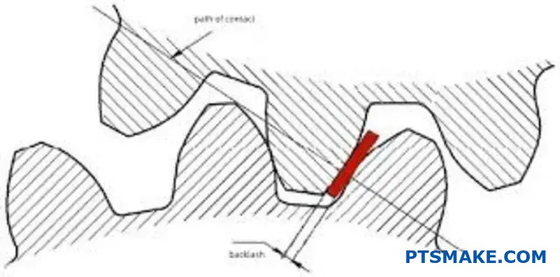
Backlash is a double-edged sword in gear systems. It is the small gap between mating gear teeth. This gap is crucial.
It prevents gears from jamming due to thermal expansion. It also creates space for lubrication.
However, it introduces trade-offs. Backlash can lead to positional inaccuracies. It also causes impact loads when the gear direction changes. This balance is key for performance.
The Good: Why Some Backlash is Essential
A gear system with zero backlash would fail quickly. The gap allows a lubricant film to form. This reduces friction and wear.
| Benefit of Backlash | Consequence of No Backlash |
|---|---|
| Prevents Jamming | Seizing due to heat |
| Allows Lubrication | High Friction & Rapid Wear |
| Accommodates Errors | Stress Concentration |
The Bad: Negative Performance Impacts
On the other hand, too much backlash is harmful. It directly impacts the precision of the system. This is a major issue in robotics and CNC machining.
Backlash is often seen as a necessary evil. While it ensures smooth operation by preventing jams and aiding lubrication, its presence introduces significant challenges. The most immediate problem is positional error, especially in systems requiring precise movements.
Impact Loads on Reversal
When a gear system reverses direction, the driving tooth disengages. It travels across the backlash gap before contacting the opposite tooth flank. This creates an impact load.
This constant hammering during the meshing cycle4 accelerates wear. It can lead to tooth fatigue and eventual failure. In past projects at PTSMAKE, we’ve seen how minimizing this impact is critical for long-term reliability.
Positional Inaccuracy
In applications like automation and aerospace, precision is everything. Backlash creates a "dead zone" where the output shaft can move without input shaft movement. This directly translates to lost motion and reduced accuracy.
The table below shows how backlash requirements change with the application. This highlights the need for custom solutions.
| Application | Typical Backlash Tolerance | Primary Concern |
|---|---|---|
| Robotics | Very Low (arc-minutes) | Positional Accuracy |
| Automotive Transmission | Moderate | Noise, Durability |
| Industrial Conveyor | High | Cost, Jam Prevention |
At PTSMAKE, we help clients find the perfect balance. We design gear systems that meet their specific precision and durability needs. This often involves advanced gear manufacturing techniques.
Backlash is a critical design parameter. It is necessary for lubrication and preventing jams. However, it negatively affects precision and can cause impact loads, leading to wear. Proper management is key to optimal gear system performance.
What defines a gear’s module or diametral pitch?
Module and Diametral Pitch are the keys to gear tooth size. They are fundamental parameters. These values decide if two gears can work together.
They also impact the gear’s strength and the tools needed for manufacturing. Understanding them is the first step in any gear design project.
The Core Measurement
Essentially, these terms define the size of the gear teeth. You can’t mix and match them. A gear with a specific module will only mesh with another gear of the same module.
Metric vs. Imperial Systems
The choice between module and diametral pitch often depends on your region. One is metric, the other is imperial.
| System | Parameter | Relationship to Tooth Size |
|---|---|---|
| Metric | Module (m) | Larger module = Larger teeth |
| Imperial | Diametral Pitch (DP) | Larger DP = Smaller teeth |
Choosing the right module or diametral pitch goes beyond simple measurement. It has major consequences for the entire project. This choice directly affects a gear’s performance and manufacturing cost.
Impact on Interchangeability
This is the most critical rule. Gears must have the same module or diametral pitch to mesh correctly. A 2-module gear will never work with a 2.5-module gear. There is no compromise here. This ensures standardized compatibility.
How it Affects Gear Strength
The size of the gear tooth is directly related to its strength. A larger tooth can handle more load.
Therefore, a gear with a larger module (or a smaller diametral pitch) will be stronger. This is a key consideration in high-torque applications. The pitch circle5 is the theoretical basis for these calculations.
Manufacturing and Tooling Considerations
Manufacturing gears requires specific cutting tools, like hobs or cutters. Each tool is designed for a specific module or pitch. Using standard values is highly recommended.
At PTSMAKE, we often advise clients to use standard sizes. This reduces tooling costs and shortens lead times. Custom tooling is possible but adds significant expense and time to a project.
| Parameter | Implication for Strength | Implication for Tooling |
|---|---|---|
| High Module (e.g., m=4) | Stronger, larger teeth | Requires m=4 tools |
| Low Module (e.g., m=1) | Weaker, smaller teeth | Requires m=1 tools |
| Low DP (e.g., DP=8) | Stronger, larger teeth | Requires DP=8 tools |
| High DP (e.g., DP=32) | Weaker, smaller teeth | Requires DP=32 tools |
Module and Diametral Pitch are the foundational specifications for gear teeth. They determine size, strength, and interchangeability. Making the right choice directly impacts manufacturing tooling, overall cost, and the final performance of the gear system.
What is the contact ratio and why does it matter?
The contact ratio is a critical number in gear design. It tells you the average number of tooth pairs in contact at any given moment.
A higher ratio means better performance. It directly impacts how smoothly and quietly your system runs. It’s a key factor we analyze at PTSMAKE.
Key Performance Impacts
A good contact ratio distributes the load. This reduces stress on individual gear teeth. It also ensures a continuous transfer of power. This is vital for high-precision machinery.
Below is a simple breakdown:
| Factor | High Contact Ratio | Low Contact Ratio |
|---|---|---|
| Load Sharing | Better | Worse |
| Smoothness | Higher | Lower |
| Noise Level | Lower | Higher |
This simple metric is the foundation for a reliable gear transmission system. We always aim for an optimal balance.
How It Influences Gear Performance
Understanding the contact ratio helps us predict and enhance gear system behavior. It’s about more than just numbers; it’s about real-world results.
Load Sharing and Reliability
When more teeth share the load, the stress on each tooth decreases significantly. This simple principle is fundamental to preventing premature wear and tooth breakage.
This distribution minimizes peak stress on any single tooth, reducing the risk of failures related to pitting6. In past projects, focusing on this has extended gear life dramatically.
A higher contact ratio leads to a more robust and reliable transmission. This is a non-negotiable for industries like aerospace and automotive.
Operational Smoothness and Noise
A contact ratio above 1.0 ensures that a new pair of teeth engages before the previous pair disengages. This creates a seamless power transfer.
The result is smoother, quieter operation. It eliminates the shock and vibration common in systems with lower contact ratios. This is especially important for medical devices and consumer electronics.
The table below shows how the ratio affects applications.
| Contact Ratio Value | Primary Benefit | Ideal Application |
|---|---|---|
| > 1.2 | Basic Functionality | Low-speed, low-load systems |
| > 1.5 | Smoother, Quieter | Automotive transmissions |
| > 2.0 | High Reliability | Aerospace, precision machinery |
A higher contact ratio directly improves gear performance. It enhances load sharing, which leads to smoother operation, lower noise, and greater overall transmission reliability. This is crucial for demanding applications where failure is not an option.
What is interference in gearing and what causes it?
When gears mesh, only the involute portions of the teeth should touch. This design ensures smooth, rolling contact and predictable power transmission.
Interference is what happens when this rule is broken. The non-involute part of a tooth makes contact.
The Problem with Non-Involute Contact
This unwanted contact can dig into the root of the mating gear tooth. This destructive action is known as undercutting.
In severe cases, it causes the gears to lock up completely. This is a catastrophic failure called seizure. It is fundamentally a geometric problem.
Contact Profile Consequences
| Contact Type | Action | Gear Performance |
|---|---|---|
| Involute | Smooth Rolling | Optimal and efficient |
| Non-Involute | Gouging/Digging | Failure, wear, or seizure |
This is a failure mode that is entirely preventable through careful design.
Geometric Origins of Interference
The root cause of gear interference is purely geometric. It occurs when the tip of a tooth on one gear extends beyond a critical limit.
This limit is called the interference point. It marks the start of the non-involute profile on the mating gear’s flank near its base circle.
The intended path of contact7 must remain strictly between the interference points of the two meshing gears. If it extends beyond, you get interference.
At PTSMAKE, our CNC machining processes are designed to hold tight tolerances. This precision is vital for creating the exact tooth profiles that prevent these geometric clashes in real-world applications.
Key Causal Factors
In past projects, we have identified several common geometric conditions that cause interference.
| Causal Factor | Description | Impact on Gear Mesh |
|---|---|---|
| Low Tooth Count | Pinions with very few teeth are highly susceptible to interference. | Increases risk of undercutting. |
| Low Pressure Angle | A smaller pressure angle enlarges the base circle, increasing risk. | Requires more teeth to avoid it. |
| Large Addendum | If a tooth’s addendum is too large, its tip can cross the interference point. | A direct cause of gouging. |
| Center Distance Error | Incorrect mounting can alter the mesh geometry and induce interference. | Leads to noise and wear. |
Understanding these factors is the first step. Proper gear design involves a careful balance of these parameters to ensure a smooth and interference-free mesh.
Interference is a destructive geometric clash resulting from non-involute tooth contact. It stems from design issues like low tooth counts or improper pressure angles, leading to severe undercutting or seizure and ultimately, gear failure.
How does torque transmission actually occur at the tooth mesh?
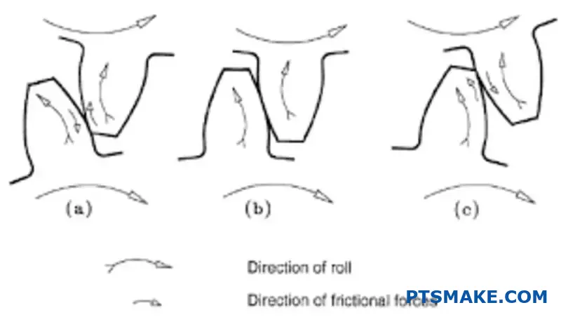
Many believe gear teeth simply roll over one another. This is an oversimplification. The actual motion is a sophisticated combination of rolling and sliding.
This dual action is fundamental. It dictates how power is transferred effectively. It also directly influences the lifespan and wear of the gear system.
The Rolling and Sliding Dynamic
Understanding this interaction is key to designing durable gears. The location of contact on the tooth face determines the type of motion.
| Motion Type | Primary Location on Tooth | Key Effect |
|---|---|---|
| Pure Rolling | Exactly at the pitch line | Efficient power transfer |
| Sliding | Away from the pitch line | Creates friction and wear |
This balance ensures continuous contact. Without it, smooth torque transmission would be impossible.

Deconstructing the Tooth Interaction
The unique involute curve of a gear tooth profile is responsible for this complex motion. This specific geometry ensures a constant velocity ratio between meshing gears, which is essential for predictable performance.
The Role of the Pitch Point
The magic happens at a specific location. At the exact pitch point8, the motion is pure rolling. This is the moment of most efficient power transfer with minimal friction.
As the contact point moves away from this line, sliding velocity increases. This sliding motion is not a flaw; it’s a necessary part of the design. It allows the teeth to engage and disengage smoothly without jamming.
The Trade-Off: Efficiency vs. Wear
However, this sliding is also the primary source of frictional heat and surface wear. At PTSMAKE, managing this trade-off is central to our manufacturing process for high-performance gears. We focus on materials and surface finishes that minimize wear.
| Contact Position | Dominant Motion | Impact |
|---|---|---|
| Tip and Root | High Sliding | Increased Wear, Heat |
| Pitch Point | Pure Rolling | Maximum Efficiency |
This intricate dance between rolling and sliding is what makes a gear work. It’s a balance of smooth operation against inevitable wear.
The motion between gear teeth is a necessary mix of rolling and sliding, dictated by the tooth profile. Pure rolling at the pitch point ensures efficiency, while sliding enables smooth engagement but also causes wear, a critical factor in gear design and manufacturing.
How does gear geometry directly influence transmission error?
The ideal involute profile of a gear is designed for one thing: perfectly smooth motion. It ensures a constant velocity ratio between meshing gears.
However, manufacturing is never perfect. Microscopic deviations always exist on the tooth surface.
From Tiny Flaws to Big Problems
These tiny flaws disrupt the smooth transfer of motion. They cause the output gear’s speed to fluctuate slightly with every tooth engagement. This is a primary source of transmission error.
| Deviation Source | Impact on Motion |
|---|---|
| Profile Error | Unstable Output Velocity |
| Surface Finish | Increased Friction & Wear |
These small but rapid speed changes create unwanted noise and vibration in the system.
The Mechanics of Fluctuation
An ideal gear pair has a contact point that moves smoothly along a theoretical straight line. This is called the line of action. This consistent contact ensures the driven gear rotates at a steady speed.
Microscopic profile deviations force this contact point to shift. It moves slightly ahead of or behind its ideal position. This tiny shift alters the effective transmission radius at that instant.
As a result, the output gear briefly accelerates or decelerates. This constant speeding up and slowing down is the physical manifestation of transmission error. Through our work at PTSMAKE, we’ve seen this directly impact high-speed applications where precision is non-negotiable.
The Ripple Effect of Imperfections
These velocity fluctuations are a direct cause of gear whine. The gear teeth essentially "tap" each other at a frequency determined by the rotational speed, and any inconsistency in that tapping creates noise.
This creates a kinematic error9 that radiates through the entire assembly. Over time, the resulting vibration can lead to accelerated wear on the gear teeth and bearings. It can even compromise the performance of the final product.
| Feature | Ideal Gear | Real-World Gear |
|---|---|---|
| Contact Path | Perfectly straight line | Deviates from the line |
| Velocity Ratio | Perfectly constant | Fluctuates with rotation |
| Noise Level | Minimal (theoretically) | Measurable and variable |
Microscopic flaws on a gear’s involute profile disrupt smooth motion, causing output velocity to fluctuate. This transmission error is a root cause of gear noise and vibration, negatively affecting performance and durability. Precision manufacturing is crucial to mitigate these issues.
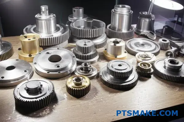
How are gear types classified by shaft orientation?
Understanding gear classification starts with the shafts. The position of the input and output shafts relative to each other is the primary sorting method.
This mental model helps you quickly narrow down options. You can immediately filter gear types based on your machine’s physical layout.
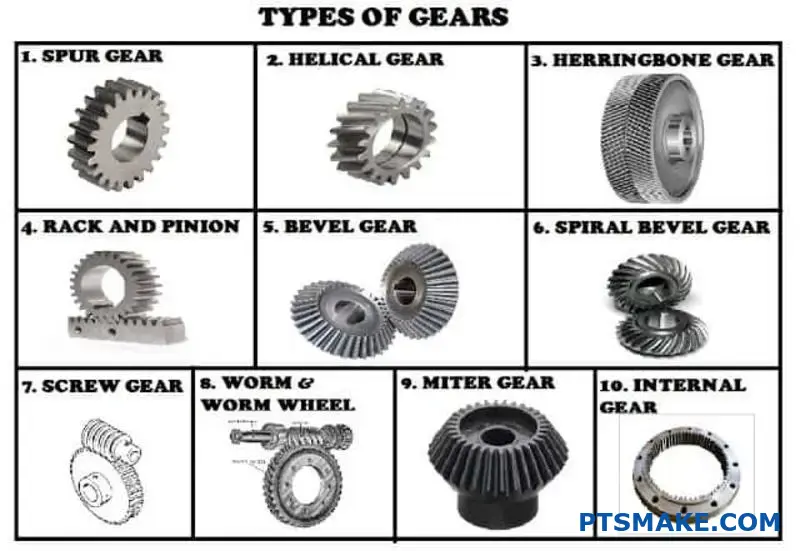
At PTSMAKE, we work with three main categories. Each serves a distinct mechanical purpose, dictating the gear’s form and function.
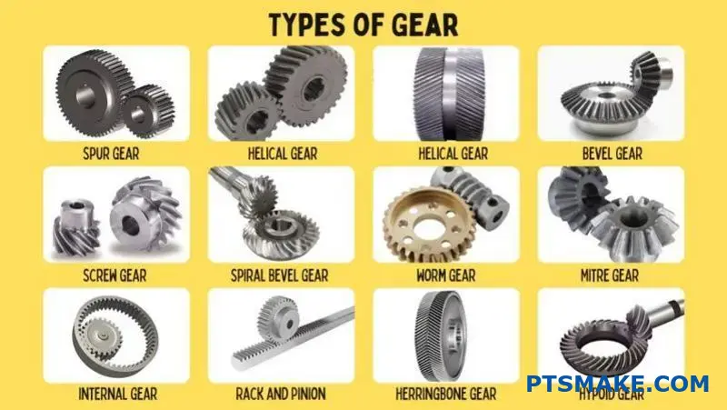
| Shaft Orientation | Primary Gear Examples |
|---|---|
| Parallel | Spur, Helical |
| Intersecting | Bevel |
| Non-Intersecting, Non-Parallel | Worm, Hypoid |
This table provides a quick reference for initial design choices.
Parallel Axis Gears
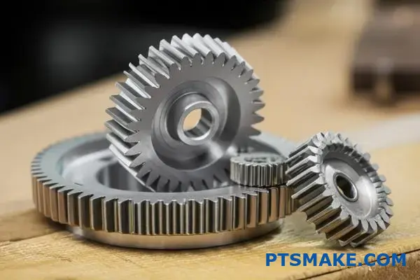
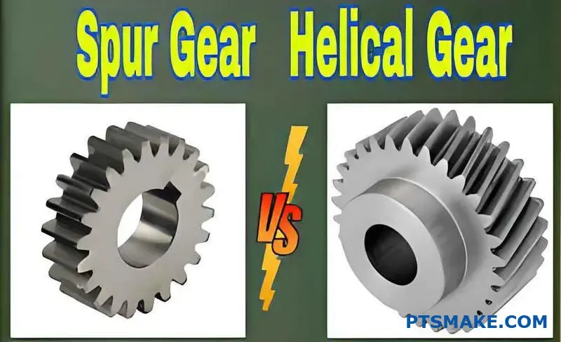
This is the most common arrangement. Spur and helical gears fall into this category. Their shafts run parallel, making them ideal for straightforward power transmission.
Spur gears are simple and cost-effective. Their straight teeth are excellent for moderate speeds. However, they can generate more noise during operation.
Helical gears have angled teeth. This design allows for smoother and quieter engagement, especially at higher speeds. They can also handle heavier loads.
Intersecting Axis Gears
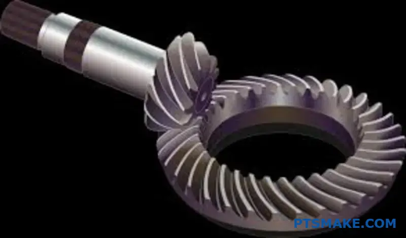
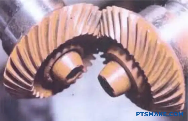
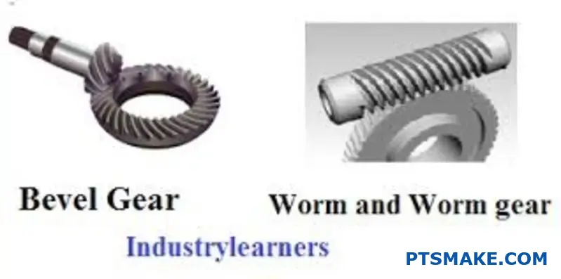
When you need to turn a corner with your power transmission, you use this group. Bevel gears are the classic example here. Their shafts typically meet at a 90-degree angle, though other angles are possible.
Think of a hand drill’s mechanism or a car’s differential. These are perfect applications. They efficiently transfer power between shafts that cross paths.
Non-Intersecting, Non-Parallel Axis Gears
This group handles the most complex orientations. The shafts are on different planes and never cross.
Worm gears are famous in this category. They offer very high reduction ratios in a compact space. The unique sliding motion ensures the conjugate action10 is maintained for smooth power transfer. They can also be self-locking.
Hypoid gears are another key example. They are similar to bevel gears but with offset axes, allowing for even smoother and stronger performance.
| Group | Key Feature | Common Application |
|---|---|---|
| Parallel | Transmit power between parallel shafts | Conveyor systems, transmissions |
| Intersecting | Change power transmission direction | Differentials, hand drills |
| Non-Intersecting | High gear ratios, offset shafts | Elevators, automotive rear axles |
Classifying gears by shaft orientation—parallel, intersecting, or non-intersecting—simplifies selection. This framework helps engineers identify the most suitable gear type for their spatial and mechanical requirements, ensuring an efficient and effective design from the start.
What are the practical trade-offs between spur and helical gears?
Choosing the right gear is crucial. It often comes down to spur versus helical gears. The decision impacts performance, cost, and design complexity.
Spur gears are the essence of simplicity. Their straight teeth are easy to manufacture. This simplicity also means they produce no axial thrust, simplifying bearing requirements.
Helical gears, however, offer smoother, quieter operation due to their angled teeth. This gradual engagement allows for higher load capacities.
Key Design Differences
| Feature | Spur Gear | Helical Gear |
|---|---|---|
| Tooth Orientation | Straight, parallel to axis | Angled to axis |
| Engagement | Abrupt, full tooth width | Gradual, starting at one end |
| Noise Level | Higher | Lower |
| Axial Thrust | None | Generated |
In-Depth Comparison
When selecting a gear type, the application’s specific needs are paramount. It’s a balance between performance and simplicity.
Spur Gear Advantages
Spur gears are mechanically simple. This leads to lower manufacturing costs and easier maintenance. In many projects at PTSMAKE, we use them for applications where speed and noise are not critical factors. Their biggest advantage is the absence of axial load, which simplifies the overall system design.
Helical Gear Considerations
Helical gears are superior for high-speed and heavy-load applications. Their angled teeth engage more gradually, resulting in less vibration and quieter operation. Our tests show they can handle significantly more load than a spur gear of the same size.
However, this performance comes at a cost. The angled teeth create axial thrust11, a force parallel to the gear’s axis. This force must be managed with appropriate thrust bearings, which adds complexity and cost to the final assembly.
Detailed Performance Trade-offs
| Aspect | Spur Gear | Helical Gear |
|---|---|---|
| Load Capacity | Good | Excellent |
| Speed Limit | Lower | Higher |
| Noise/Vibration | High | Low |
| Manufacturing Cost | Lower | Higher |
| Bearing Needs | Simple | Requires thrust bearings |
| Efficiency | Slightly higher | Slightly lower (due to sliding) |
The choice hinges on your priorities. Spur gears offer a cost-effective, simple solution. Helical gears provide superior, quieter performance for demanding applications but require more complex designs to handle the resulting axial loads.
When should one choose bevel gears over worm gears?
Choosing the right gear is critical. It’s about matching the tool to the task. Bevel gears are champions of efficient right-angle power transfer. They are ideal when you need to maintain speed and power.
Worm gears offer a different set of benefits. They excel at providing very high reduction ratios in a compact space. This makes them perfect for certain specialized applications.
Key Functional Differences
Let’s break down their core functions. This simple comparison helps clarify their best uses.
| Feature | Bevel Gear | Worm Gear |
|---|---|---|
| Primary Use | Efficient 90° Power Transfer | High Gear Reduction |
| Efficiency | High (95-99%) | Lower (50-90%) |
| Self-Locking | No | Yes (often) |
| Heat Generation | Low | High |
This table shows a clear trade-off. You choose based on whether efficiency or high reduction is your priority.
Analyzing Application Scenarios
In projects at PTSMAKE, the application always dictates the gear choice. We don’t pick a gear and hope it works; we analyze the system’s needs first. This ensures optimal performance and longevity for the final product.
When Bevel Gears Shine
Bevel gears are the go-to for high-speed, high-efficiency right-angle drives. Think of applications where power loss must be minimal. Their design allows for smooth, quiet operation at high RPMs.
For example, in automotive differentials, a bevel gear system efficiently transfers power from the driveshaft to the axles. This allows the wheels to rotate at different speeds when turning. Printing presses also use them for precise, fast power distribution.
The Niche for Worm Gears
Worm gears dominate in applications requiring massive speed reduction and high torque. A classic example is a conveyor belt system. The motor runs at high speed, but the belt needs to move slowly and with great force.
Their most significant advantage is self-locking. Once the input stops, the output shaft cannot move backward. This inherent braking is a critical safety feature in elevators and lifting equipment. The sliding action of the worm gear generates friction, which prevents back-drivability12.
Application-Specific Comparison
Here is a look at specific scenarios we’ve encountered. This helps illustrate the decision-making process.
| Application | Recommended Gear | Reason |
|---|---|---|
| Automotive Differentials | Bevel Gear | High efficiency, handles high speed |
| Conveyor Systems | Worm Gear | High reduction ratio, high torque |
| Hand Drills | Bevel Gear | Compact right-angle power transfer |
| Elevator/Lifts | Worm Gear | Self-locking for safety, high torque |
| Printing Machinery | Bevel Gear | Precision and speed required |
Choosing the right gear type early in the design phase is crucial for success.
Bevel gears are for efficient, high-speed, right-angle power transmission. Worm gears are ideal for applications needing significant gear reduction, high torque, and the safety of a self-locking mechanism. The choice depends entirely on your specific operational needs.
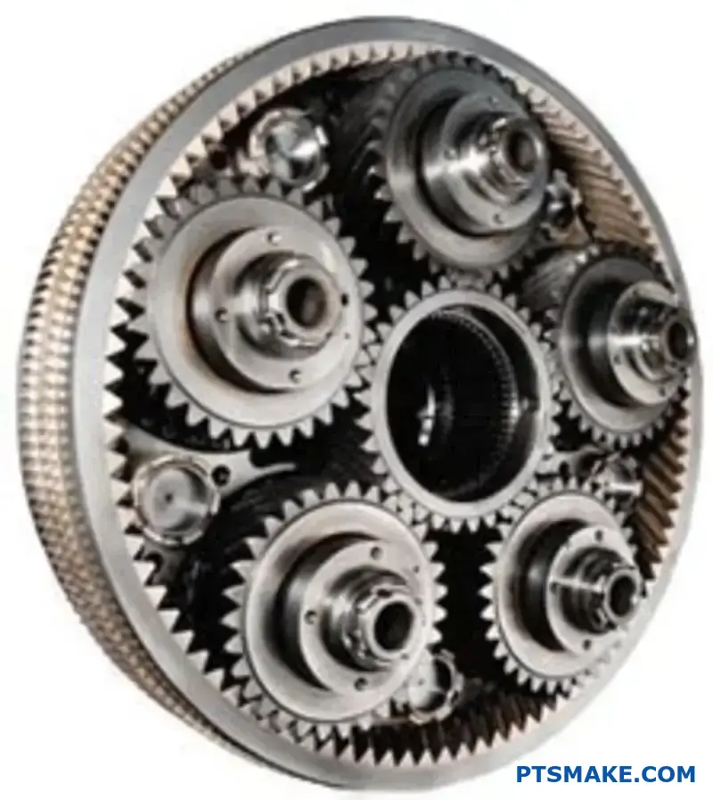
What defines a planetary gear train’s unique properties?
Planetary gear systems are engineering marvels. Their unique properties come from a clever design. It allows for high power in a small space.
Their coaxial nature is a key benefit. This means the input and output shafts are aligned. It makes them perfect for tight applications.
They also offer amazing torque density. Multiple planet gears share the load. This prevents any single gear from taking too much stress. It allows for a very compact and powerful unit.
| Property | Benefit |
|---|---|
| Coaxial Shafts | Space-saving, compact design |
| Load Sharing | High torque capacity, durability |
| Versatility | Multiple gear ratios in one unit |
A Deeper Look at the Core Properties
The design of a planetary gear train directly creates its powerful advantages. Understanding these properties helps in choosing the right system for an application.
Coaxial Nature for Compactness
The inline arrangement of the input and output shafts is a game-changer. In many projects we’ve handled at PTSMAKE, especially in robotics and automotive, space is a luxury. This coaxial setup allows the drivetrain to be streamlined and compact.
High Torque Density and Load Sharing
Unlike a simple gear pair, a planetary system distributes the load. It is shared across multiple planet gears. This means it can handle much higher torque without needing larger gears.
This load distribution significantly increases the system’s lifespan. The intricate movement of the planets is a form of epicyclic motion13. This motion ensures stress is balanced throughout the gear train.
Versatile Kinematic Possibilities
This is where planetary systems truly shine. You can achieve different outputs by simply holding one component stationary. This offers incredible design flexibility from a single gear assembly.
| Fixed Component | Input | Output | Common Result |
|---|---|---|---|
| Ring Gear | Sun Gear | Planet Carrier | Speed Reduction |
| Sun Gear | Ring Gear | Planet Carrier | Lower Reduction |
| Planet Carrier | Sun Gear | Ring Gear | Reverse or Overdrive |
The unique properties of a planetary gear train stem from its coaxial design, load-sharing mechanism, and kinematic versatility. These features allow for high torque transmission in a compact, adaptable package, making it a superior choice for many advanced mechanical applications.
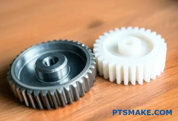
How do gear materials dictate application and performance?
Choosing the right gear material is a critical first step. It dictates everything from load capacity to operational noise. Think of it as a foundation. A poor choice here can compromise the entire system.
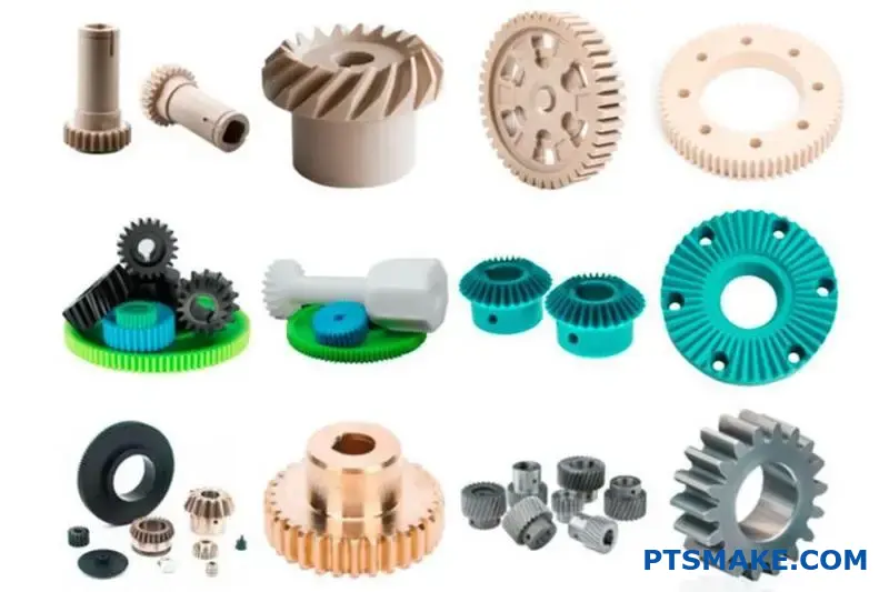
The main material families are steels, plastics, and bronzes. Each offers a unique profile of properties.
Common Gear Materials
Your application’s demands will point you to the right material. High-torque systems need strength, while medical devices might prioritize quiet operation.
| Material | Key Property | Ideal Application |
|---|---|---|
| Alloy Steel | High Strength & Toughness | Automotive transmissions |
| Plastic (e.g., Nylon) | Self-lubricating, Quiet | Office equipment, consumer goods |
| Bronze | Low Friction, Conformability | Worm gears, high-load bushings |
This selection process is fundamental to successful gear design.
A deeper dive reveals a trade-off between properties. It’s not just about picking the strongest material. We must match specific characteristics to operational demands for optimal performance.
Linking Properties to Demands
Hardness, for example, resists surface wear and indentation. This is crucial for gears under high contact stress. However, extreme hardness can sometimes lead to brittleness, reducing a gear’s ability to withstand shock loads.
Toughness is the material’s capacity to absorb energy and deform without fracturing. This is essential in applications like industrial machinery where sudden starts, stops, and impacts are common. The Tribological properties14 of a material are also key, governing friction and wear over the gear’s lifetime.
At PTSMAKE, we guide clients through these decisions. Our expertise in both CNC machining metals and injection molding plastics allows us to provide the best-fit solution. We analyze the entire operational context.
| Property | Why It Matters | Specific Demand |
|---|---|---|
| Hardness | Resists surface wear | High-pressure contact points |
| Toughness | Prevents fracture from impact | Shock-loading environments |
| Wear Resistance | Ensures long service life | Continuous or abrasive operation |
| Corrosion Resistance | Prevents degradation | Chemical or humid environments |
This careful balancing act ensures the gear not only works but excels.
Selecting a gear material is a balancing act. You must weigh properties like hardness, toughness, and wear resistance against specific application demands. This decision is foundational to the gear’s performance, efficiency, and ultimate lifespan in the field.
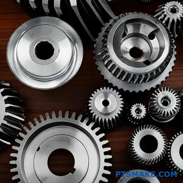
What are the primary gear manufacturing processes available?
Choosing the right gear manufacturing process is crucial. It directly impacts your final product’s quality, cost, and performance. The main methods are forming and machining.
Each technique offers unique benefits. Let’s explore the most common ones.
Key Manufacturing Methods
Hobbing
This is a high-speed machining process. It’s excellent for producing spur and helical gears. It is very efficient for medium to high-volume production runs.
Shaping
Shaping is more versatile than hobbing. It can create internal gears and features that hobbing cannot. However, it is generally a slower process.
Grinding
Grinding is a finishing process. It’s used after machining to achieve very high precision and a smooth surface finish. This is essential for high-performance applications.
Forging
Forging is a forming process. It shapes metal using compressive forces. This method creates strong, durable gear blanks but requires secondary machining for final tooth profiles.
Here’s a quick comparison:
| Process | Primary Use | Advantage |
|---|---|---|
| Hobbing | High-volume production | Fast and cost-effective |
| Shaping | Internal gears, complex shapes | Versatile |
| Grinding | High-precision finishing | Superior accuracy |
| Forging | Creating strong blanks | Excellent material strength |
The best method depends entirely on your specific needs. There is no single "best" process for every gear. It’s a balance of precision, volume, material, and budget.
Deeper Dive into Process Selection
When helping clients at PTSMAKE, we focus on the final application. A gear for a high-speed automotive transmission has different needs than one for a simple conveyor system.
Precision vs. Cost
Grinding delivers exceptional accuracy. It is ideal for applications where minimal noise and vibration are critical. However, this precision comes at a higher cost.
Forging, on the other hand, is cost-effective for high volumes. But it lacks the fine detail needed for a finished gear. It almost always requires secondary machining processes. This adds steps and cost.
Impact on Gear Performance
The manufacturing process directly affects the gear’s mechanical properties. Forging aligns the material’s grain structure, increasing strength and fatigue resistance.
Machining processes like hobbing and shaping create the precise tooth geometry, such as the involute profile15, which is critical for smooth power transmission. Grinding refines this profile to near perfection.
Based on our tests, a ground gear can handle higher loads and operate more quietly than a hobbed-only gear.
| Factor | Hobbing | Shaping | Grinding | Forging (Blank) |
|---|---|---|---|---|
| Precision | Good | Good | Excellent | Low |
| Speed | Fast | Medium | Slow | Very Fast |
| Cost | Medium | Medium-High | High | Low (per unit) |
| Strength | Good | Good | Good | Excellent |
Selecting the right process involves a detailed analysis of these trade-offs. It ensures the final gear performs reliably and meets budget constraints.
Choosing a gear manufacturing method is a critical decision. It requires balancing the need for quality, performance, and cost. Each process offers distinct advantages suited for different applications and production volumes.
How do AGMA/ISO standards structure gear quality levels?
To ensure consistency, standards quantify gear precision. They don’t just say "high quality." Instead, they use measurable parameters.
This creates a clear language for everyone involved. Designers, manufacturers, and inspectors all work from the same playbook.
Key Measurement Parameters
The core of these standards revolves around specific deviations from a perfect gear. The main ones are profile, lead, and pitch. Each tells a different part of the quality story.
What They Control
| Parameter | Controls | Impact on Performance |
|---|---|---|
| Profile Deviation | The accuracy of the tooth curve (involute shape) | Smoothness, noise |
| Lead Deviation | The alignment of the tooth along its axis | Load distribution |
| Pitch Deviation | The spacing consistency between adjacent teeth | Vibration, stress |
Understanding these ensures you can specify a gear that meets performance needs without over-engineering.
Quantifying precision is about setting acceptable limits for error. Both AGMA and ISO standards assign quality numbers. A lower number (like ISO 4) means tighter tolerances and a more precise gear. A higher number (like ISO 12) allows for more deviation.
The Role of Tolerances
Tolerances are the maximum allowable deviation for each parameter. For a high-precision aerospace gear, these tolerances might be just a few micrometers. This is a very small margin for error.
At PTSMAKE, we use high-resolution CMMs to verify these values. We map each tooth to ensure it’s within the specified tolerance band. This data is critical for quality assurance.
From Specification to Production
A designer specifies a quality level, like AGMA Q10. We then translate that into specific micron-level tolerances for our CNC machining and gear cutting processes. Each manufacturing step is controlled to meet these targets.
This process ensures that the final gear performs exactly as intended. It eliminates guesswork and subjectivity. Every gear part must meet these strict criteria, including its total composite deviation and even the specific flank tolerance16 for each tooth surface.
Simplified Tolerance Comparison
Here is how tolerances might change with quality levels. Note that actual values depend on gear size and other factors.
| Quality Level | Relative Profile Tolerance | Relative Pitch Tolerance |
|---|---|---|
| High Precision (ISO 5) | ± 5 µm | ± 4 µm |
| General Use (ISO 8) | ± 12 µm | ± 10 µm |
| Low Precision (ISO 11) | ± 30 µm | ± 25 µm |
This structure makes procurement straightforward. You are buying a component defined by measurable, repeatable data.
AGMA and ISO standards quantify gear precision through specific parameters like profile, lead, and pitch deviation. This system of numbered quality levels and defined tolerances ensures clear communication and consistent manufacturing, enabling precise procurement for any application.
What are the different types of gear failure modes?
To solve a problem, you must first understand it. Gear failure is no different. Identifying the failure mode is the first step in diagnosing the root cause. This helps prevent future issues.
Let’s break down the most common failure types. Think of this as building your diagnostic foundation. Each mode tells a different story about the gear’s life.
Bending Fatigue
This is a classic failure. It results in a tooth breaking off at its root. This is often caused by repeated high loads. The crack starts small and grows over time.
Surface Fatigue
This affects the gear tooth’s surface. It doesn’t break the whole tooth. Instead, small pieces flake away. We see this as pitting or spalling.
A quick comparison can help clarify:
| Failure Mode | Location | Cause | Result |
|---|---|---|---|
| Bending Fatigue | Tooth Root | Repetitive Bending Stress | Complete Tooth Breakage |
| Surface Fatigue | Tooth Surface | Repetitive Contact Stress | Pitting, Spalling |
Understanding the primary failure modes is just the start. The details within each category reveal more about the operating conditions. We need to dig a little deeper.
Exploring Different Types of Wear
Wear is a gradual loss of material. It’s different from the sudden fracture of fatigue. It happens slowly over many cycles.
Abrasive Wear
This occurs when hard particles slide against the gear surface. Think of it like sandpaper. These particles can be contaminants in the lubricant or debris from other parts. They scratch and groove the tooth flank.
Adhesive Wear
This happens when gear teeth surfaces slide under pressure. The microscopic peaks, or asperities17, can weld together. As the gears rotate, these welds break, pulling material from one surface to the other.
Understanding Scuffing
Scuffing is a severe form of adhesive wear. It’s often caused by a breakdown of the lubricant film between teeth. This leads to direct metal-to-metal contact, high friction, and localized welding. The result is a rough, torn surface texture.
At PTSMAKE, we manage these risks through precise material selection and surface finish controls.
| Failure Type | Key Mechanism | Visual Cue |
|---|---|---|
| Abrasive Wear | Scratching by hard particles | Fine lines, grooves |
| Adhesive Wear | Micro-welding and tearing | Material transfer, galling |
| Scuffing | Lubricant failure, severe adhesion | Rough, torn, discolored patches |
Recognizing the four main gear failure modes is critical. These are bending fatigue, surface fatigue, wear, and scuffing. Each has distinct causes and visual signs, which guide effective troubleshooting and prevention strategies.
How do different gear arrangements create specific speed ratios?
Different gear arrangements are the heart of mechanical design. They allow us to control speed and torque with precision. It’s all about the math behind the teeth.
The relationship between gears dictates the final output. Understanding this is key to building efficient machinery. Let’s look at the core types.
Simple Gear Trains
A simple gear train involves two gears meshing. The ratio is straightforward: the tooth count of the driven gear divided by the driver gear.
| Driver Gear Teeth | Driven Gear Teeth | Speed Ratio |
|---|---|---|
| 20 | 40 | 2:1 |
| 15 | 60 | 4:1 |
Compound and Epicyclic Systems
More complex systems like compound and epicyclic gear trains offer greater flexibility. They allow for much larger speed reductions in a compact space.
To achieve a desired output, we manipulate tooth counts and configurations. The goal is to get the perfect balance of speed and torque for the application. It’s a fundamental concept in engineering.
Understanding Gear Train Configurations
A simple gear train is the most basic setup. It consists of a driver gear and a driven gear. If you need a large speed reduction, the driven gear becomes massive. This is often impractical.
Compound gear trains solve this problem. They use multiple gear pairs on common shafts. This allows for multiplying gear ratios. The result is a significant speed reduction in a much smaller physical footprint. We often use this setup in projects at PTSMAKE requiring high torque.
The Complexity of Epicyclic Gear Trains
Epicyclic, or planetary, gear trains are more complex but incredibly versatile. They have a central "sun" gear. Multiple "planet" gears rotate around it. An outer "ring" gear meshes with the planets.
This arrangement can achieve very high gear ratios. Different outputs are possible by holding one component stationary. This reduction in speed results in a significant increase in torque, which is known as Mechanical Advantage18. It’s a powerful tool for advanced applications.
| Gear Train Type | Key Feature | Common Use Case |
|---|---|---|
| Simple | Direct Drive | Basic machinery |
| Compound | Ratio Multiplication | Industrial gearboxes |
| Epicyclic | High Ratios, Compact | Automatic transmissions |
Understanding gear arrangements like simple, compound, and epicyclic trains is crucial. By manipulating tooth counts and configurations, we can precisely control speed, torque, and the resulting mechanical advantage to meet specific design requirements for any application.
How do you perform a basic gear train design calculation?
A basic gear train design calculation follows a clear workflow. It is a systematic process, not guesswork. It all begins with understanding your specific needs for the application.
The Core Workflow
First, you must define the input and output requirements. This includes speed, torque, and any space constraints. These parameters are your foundation. After that, you select the appropriate gear types and materials. Finally, you perform preliminary sizing calculations.
| Design Stage | Key Objective |
|---|---|
| 1. Requirements | Define speed, torque, and space. |
| 2. Selection | Choose gear type and material. |
| 3. Sizing | Calculate initial gear dimensions. |
This structured approach ensures you meet performance targets efficiently.
Breaking Down the Calculation Steps
A successful design hinges on getting the details right from the start. Each step builds upon the last, so precision is key throughout the entire process.
Defining Requirements
Your first task is to clearly define the operational parameters. What is the input speed from the motor? What is the required output torque for the load? These numbers dictate every subsequent decision in the gear train design. Getting this wrong leads to failure.
Gear Type and Material Selection
Next, you select the gear type. The choice depends on factors like shaft orientation and efficiency needs. In our projects at PTSMAKE, we guide clients on material selection. Steel is great for high-torque CNC machined gears. Polymers are ideal for quieter, injection-molded gears. The goal is to balance performance, cost, and manufacturability. The Contact Ratio19 is also a critical factor here.
Preliminary Sizing Calculations
With requirements and selections made, you can begin sizing. This involves calculating the gear ratio to achieve the desired speed change. You will also determine the number of teeth and the pitch diameter for each gear. These calculations provide the initial blueprint for manufacturing.
| Gear Type | Common Application | Primary Advantage |
|---|---|---|
| Spur Gear | Simple power transmission | Easy to manufacture |
| Helical Gear | Automotive transmissions | Smooth, quiet operation |
| Bevel Gear | Right-angle power transfer | Changes power direction |
| Worm Gear | High reduction ratios | Self-locking capability |
A structured gear design workflow transforms requirements into a functional component. This process, from defining speed and torque to initial calculations, ensures the final gear train performs reliably and meets all specifications from the outset.
What steps are involved in specifying gear tolerances?
Specifying gear tolerances begins with industry standards. You must use frameworks like AGMA or ISO. These standards provide a quality number.
This number acts as a shorthand. It defines the overall precision of the gear.
Selecting a Quality Number
A higher number means tighter tolerances. For example, Q12 might be for a commercial power tool. Q8 is for more demanding applications. It is a balance between performance needs and budget.
Defining Tolerances on Drawings
Once you select a quality number, translate it. Specify key geometric tolerances on your manufacturing drawing.
| Tolerance Type | Controlled Feature |
|---|---|
| Runout | Concentricity of teeth to axis |
| Profile Error | Deviation from ideal tooth form |
| Pitch Error | Spacing between adjacent teeth |
This ensures the manufacturer understands exactly what to produce.
Using standards like AGMA 2015 or ISO 1328 is the foundation. These documents are comprehensive. They can feel overwhelming. The key is to focus on what matters for your specific application. Don’t over-specify.
Balancing Cost and Performance
A common mistake is choosing a higher quality number than necessary. This drives up manufacturing costs significantly. Each step up in quality can increase cost, sometimes exponentially.
At PTSMAKE, we often guide clients on this. We help them find the sweet spot. We ensure the gear performs reliably without unnecessary expense.
From Quality Number to Specific Controls
A quality number is a good starting point. But for critical applications, it’s not enough. You should specify individual tolerances on the drawing. This removes any ambiguity for the manufacturer.
For instance, instead of just noting "AGMA Q10," you define specific limits for tooth profile, lead, and runout. You might also specify the total composite error20, which gives a good overview of the gear’s functional quality.
This detailed approach gives you more control. It ensures the most critical aspects of the gear geometry are prioritized during manufacturing and inspection.
| Standard | Primary Region | Quality Scale |
|---|---|---|
| AGMA | North America | Q3-Q15 (Higher is better) |
| ISO | International | 1-12 (Lower is better) |
| DIN | Germany | 1-12 (Lower is better) |
Understanding these differences is vital when working with global partners.
Specifying gear tolerances involves using AGMA/ISO standards to pick a quality number. This choice must balance performance with cost. Then, translate this into specific geometric tolerances on the manufacturing drawing to ensure clarity and achieve the desired functional outcome.
How do you analyze forces on shafts and bearings?
Analyzing forces from a gear mesh is vital. It starts with a free-body diagram (FBD). This simple sketch visually maps every force acting on the shaft.
The Purpose of a Free-Body Diagram
An FBD isolates a component. It shows all external forces and moments. This clarity is the first step toward accurate calculations. It prevents critical design errors.
Identifying Key Forces
We must identify three main forces. These forces originate from the gear interaction.
| Force Type | Direction | Impact |
|---|---|---|
| Tangential | Tangent to the pitch circle | Transmits torque |
| Radial | Towards the shaft center | Pushes shafts apart |
| Axial | Along the shaft axis | Creates thrust loads |
Calculating Gear Mesh Forces
Once you have your FBD, the next step is calculation. Each force component has a specific formula. The tangential force is the easiest. It’s simply the torque divided by the pitch radius. This force does the actual work.
The radial force acts to separate the gears. It is calculated using the pressure angle. This force directly loads the bearings, causing deflection. Proper bearing selection depends on accurately calculating it.
Axial Force Considerations
Axial, or thrust, force is present in helical and bevel gears. It’s a component of the total Resultant force21 pushing along the shaft’s axis. This force requires thrust bearings or angular contact bearings for support.
Ignoring this force can lead to rapid bearing failure. In past projects at PTSMAKE, we have seen designs fail because the initial analysis overlooked the axial loads from a helical gear.
Combining the Forces
The forces are vectors. They must be combined to find the total load on the bearings. This total load determines the required size and type of bearing.
| Force | Primary Influence | Key Calculation Variable |
|---|---|---|
| Tangential (Ft) | Torque Transmission | Torque (T) |
| Radial (Fr) | Bearing Load | Pressure Angle (φ) |
| Axial (Fa) | Thrust Load | Helix Angle (ψ) |
Our engineering team often assists clients in this analysis. We ensure the manufactured parts will perform reliably under the calculated loads. This collaboration is key to success.
Creating a free-body diagram is essential. It helps visualize and quantify tangential, radial, and axial forces from gear mesh. This accurate analysis ensures the proper selection of shafts and bearings, preventing premature component failure and ensuring system reliability.
How do you prepare a gear for assembly and mounting?
A perfectly machined gear is only as good as its installation. Proper preparation is the key to reliability and performance. It prevents premature failure and ensures smooth operation.
The Four Pillars of Gear Preparation
Let’s break down the essential steps. Each one is critical for a secure fit and long service life. This isn’t just about assembly; it’s about precision engineering. It ensures your system works as intended.
| Step | Purpose |
|---|---|
| Cleaning | Remove all contaminants |
| Inspection | Verify specifications and condition |
| Heating | Achieve a secure shrink fit |
| Alignment | Ensure correct meshing and function |
A Deeper Dive into Pre-Assembly Procedures
In our projects at PTSMAKE, we treat preparation with the same precision as our CNC machining. A small oversight here can lead to big problems later. Let’s explore each stage in more detail.
Thorough Cleaning
First, clean the gear and the shaft. Use a non-residue solvent to remove all oil, grease, and protective coatings. Any foreign particles can compromise the fit. Even a tiny metal shaving can cause significant damage over time.
Detailed Inspection
Next, inspect every critical dimension. Check the gear’s bore, keyway, and tooth profile against the engineering drawings. Use calipers, micrometers, and gauges. Look for any burrs or nicks from shipping or handling. These must be carefully removed before proceeding.
Controlled Heating for Shrink Fits
For shrink fits, heating is essential. The process uses thermal expansion22 to temporarily enlarge the gear’s bore. This allows it to slide onto the shaft for a tight interference fit upon cooling. Overheating can ruin the gear’s temper and material properties.
| Heating Method | Pros | Cons |
|---|---|---|
| Induction Heater | Fast, uniform heating, safe | Higher initial equipment cost |
| Oven | Good for multiple parts | Slower heating process |
| Oil Bath | Even heat distribution | Messy, potential fire hazard |
Precision Alignment
Finally, proper alignment is non-negotiable. Use tools like dial indicators and precision levels. You must ensure the gear is perfectly perpendicular to the shaft. Misalignment is a primary cause of noise, vibration, and excessive wear.
Meticulous preparation is fundamental for any gear installation. Following strict procedures for cleaning, inspection, controlled heating, and precise alignment ensures the assembly’s long-term performance and reliability. Skipping these steps is not an option for high-quality results.
How to balance performance, cost, and manufacturability?
Let’s walk through a real-world decision. A client needed a specific gear for a new robotics project. They had two main options.
A high-precision gear, or a lower-cost one. This is a common trade-off we see.
The Two Gear Options
We helped them evaluate both choices. One was a CNC machined steel gear. The other was an injection-molded POM gear. The differences were significant.
Here’s a quick breakdown of the initial comparison:
| Feature | High-Precision (CNC Steel) | Lower-Cost (Molded POM) |
|---|---|---|
| Unit Cost | High | Low (at scale) |
| Precision | Very High | Good |
| Lead Time | Moderate | Long (tooling) |
This simple table helped frame the core trade-offs.
Diving Deeper into the Application
The choice isn’t just about the spec sheet. It’s about the gear’s specific job. Where does it fit in the final product?
We asked the client: Is this for the main robotic arm joint? Or is it for an internal, non-critical function? The answer changes everything.
Performance vs. "Good Enough"
The high-precision steel gear offered exceptional durability. It had minimal backlash23, which was crucial for the robot’s positional accuracy.
The molded gear was much cheaper in high volumes. It was also lighter and quieter. However, its tolerances were looser. It couldn’t handle the same loads.
In our work at PTSMAKE, we guide clients through this. We help them define what "performance" truly means for their application. Often, "good enough" is the smartest engineering choice. It saves money and simplifies manufacturing.
Let’s compare the critical performance metrics we discussed.
| Performance Metric | High-Precision (CNC Steel) | Lower-Cost (Molded POM) |
|---|---|---|
| Load Capacity | Excellent | Moderate |
| Wear Resistance | Excellent | Good |
| Operational Noise | Moderate | Low |
| Weight | Heavy | Light |
Ultimately, the client chose the CNC gear for the primary joints and the molded gear for other internal systems. This hybrid approach balanced the needs of the entire project.
This case study shows the importance of context. The best gear choice depends on its specific role. Balancing cost, performance, and manufacturability requires a clear understanding of the application’s true requirements, not just chasing the highest specifications.
How do you select non-standard gears for a custom application?
What happens when a standard, off-the-shelf gear doesn’t work? This is a common challenge in custom applications with unique constraints.
You must move beyond the catalog. This means defining custom parameters to create a specialized solution. Key adjustments often involve the pressure angle and profile shift.
| Parameter | Standard Gear | Custom Gear |
|---|---|---|
| Design | General Purpose | Application-Specific |
| Constraints | Limited | Flexible |
| Performance | Acceptable | Optimized |
This approach ensures your gear performs perfectly, even when facing difficult design requirements.
Standard gears are made for common scenarios. They fail when applications demand something more. This could be due to limited space, high torque needs, or requirements for silent operation. A standard gear is a compromise, not a specialized solution.
Why Standard Gears Fall Short
In our work at PTSMAKE, we often see this issue. A client might need a gear system for a compact robotic arm. A standard gear might be too large or not strong enough. Another project could require a gear with minimal backlash for precision measuring equipment.
| Constraint | Standard Gear Issue | Custom Solution |
|---|---|---|
| Tight Space | Too bulky | Modified tooth profile |
| High Load | Prone to failure | Increased pressure angle |
| Low Noise | Vibrates | Helical cut, fine-tuning |
Defining Custom Parameters
To solve these problems, we adjust the gear’s fundamental geometry. This allows us to create a gear that is perfect for the job.
Altering the Pressure Angle
We can modify the pressure angle. A higher angle generally results in a stronger tooth. However, it can also increase stress on the bearings. A lower angle offers smoother, quieter operation but a weaker tooth base. The choice depends entirely on the application’s priority.
Applying Profile Shift
We also use profile shift24. This technique modifies the gear tooth’s position relative to its center. It allows us to adjust the center distance between two gears. It’s also crucial for preventing undercut on gears with few teeth, which enhances strength.
When standard gears can’t meet your unique constraints, defining custom parameters is essential. By adjusting elements like pressure angle and profile shift, we create a gear that is perfectly optimized for your specific application, ensuring superior performance and reliability.
How to prevent catastrophic gear failure through proactive design?
For any critical application, a reactive approach is a recipe for disaster. We must build a comprehensive design philosophy from the ground up. This isn’t just a checklist.
It’s a proactive mindset. It focuses on three core pillars. These pillars work together to maximize the reliability of every gear system.
| Design Pillar | Core Focus |
|---|---|
| Fail-Safe Features | Designing for graceful, predictable failure. |
| Material Selection | Choosing materials that exceed operational demands. |
| Validation Plan | Rigorously testing every assumption made in design. |
This strategy ensures we anticipate problems. We design solutions before they ever happen in the field.
A Deeper Look at Design Philosophy
A truly robust design philosophy integrates every stage of development. It starts with asking "what if?" and ends with empirical proof.
Incorporating Fail-Safe Features
Fail-safe doesn’t mean failure-proof. It means the gear system fails in a safe, controlled manner. Think of a shear pin. It’s designed to break first, protecting more expensive components from overload. We also consider redundant systems where a backup gear can take over if the primary one fails.
Robust Material Selection
Choosing the right material goes beyond simple strength calculations. We analyze the operating environment. This includes temperature, chemical exposure, and humidity. A material strong in a lab might degrade quickly in the real world. This deep analysis prevents premature wear. It also avoids issues related to excessive Hertzian contact stress25 between gear teeth.
The Rigorous Validation Plan
A design is only a theory until it’s tested. At PTSMAKE, our validation process is multi-layered. It confirms that the final gear performs as expected.
| Validation Stage | Purpose |
|---|---|
| Finite Element Analysis (FEA) | Simulates stress and heat under load digitally. |
| Prototype Testing | Tests physical parts for fit and function. |
| Life-Cycle Testing | Runs the gear system to simulate years of use. |
This rigorous plan leaves nothing to chance.
A robust design philosophy combines fail-safe features, meticulous material selection, and a comprehensive validation plan. This integrated approach is essential for creating reliable gear systems that can withstand the demands of critical applications.
Take Your Custom Gear Projects Further with PTSMAKE
Ready to optimize your gear designs for performance, reliability, and cost-efficiency? Contact PTSMAKE today for a free, no-obligation quote on precision CNC machining and injection molding solutions—tailored exactly to your application needs. Let’s turn your gear concepts into reality!

Learn how specific gear tooth shapes are designed to achieve perfectly synchronized motion and efficient power transmission. ↩
Learn how this angle affects gear performance, strength, and operational noise. ↩
Explore this concept to understand how force is consistently transmitted between gear teeth. ↩
Explore the mechanics of how gear teeth engage and disengage through a full rotation. ↩
Learn about the fundamental concept used to define all other gear geometry. ↩
Understand how surface fatigue can affect your gear’s performance and lifespan. ↩
Explore our guide on gear geometry principles to enhance your design accuracy. ↩
Understand the geometric importance of the pitch point for achieving optimal gear performance and longevity. ↩
Learn how this error is measured and minimized in high-precision manufacturing. ↩
Learn the principle that ensures constant velocity ratios for smooth gear operation. ↩
Learn how this force impacts your gear design and bearing selection. ↩
Learn how this mechanical property affects gear system safety and design choices. ↩
Explore the complex motion that gives planetary systems their unique reduction, overdrive, and reverse capabilities. ↩
Explore how friction, wear, and lubrication science can enhance your gear’s performance and longevity. ↩
Learn how this specific curve is essential for smooth and efficient gear power transmission. ↩
Understand the critical role flank tolerance plays in gear performance and longevity. ↩
Understand how these microscopic surface peaks influence gear lubrication and wear for better component design. ↩
Learn how this fundamental principle of physics amplifies force in your mechanical designs. ↩
Learn how this key metric affects gear noise, smoothness, and overall power transmission efficiency. ↩
Explore a detailed guide on what this inspection measurement reveals about your gear’s functional quality. ↩
Understand how different force vectors are combined into a single, comprehensive load. ↩
Understand how temperature affects material dimensions for a perfect and secure shrink fit. ↩
Learn how gear backlash impacts precision and how to manage it in your design. ↩
Learn the technical details of gear profile shift and how it solves complex design challenges. ↩
Understand how calculating this stress is crucial to preventing gear surface fatigue. ↩