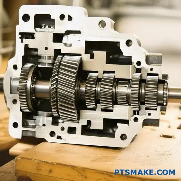
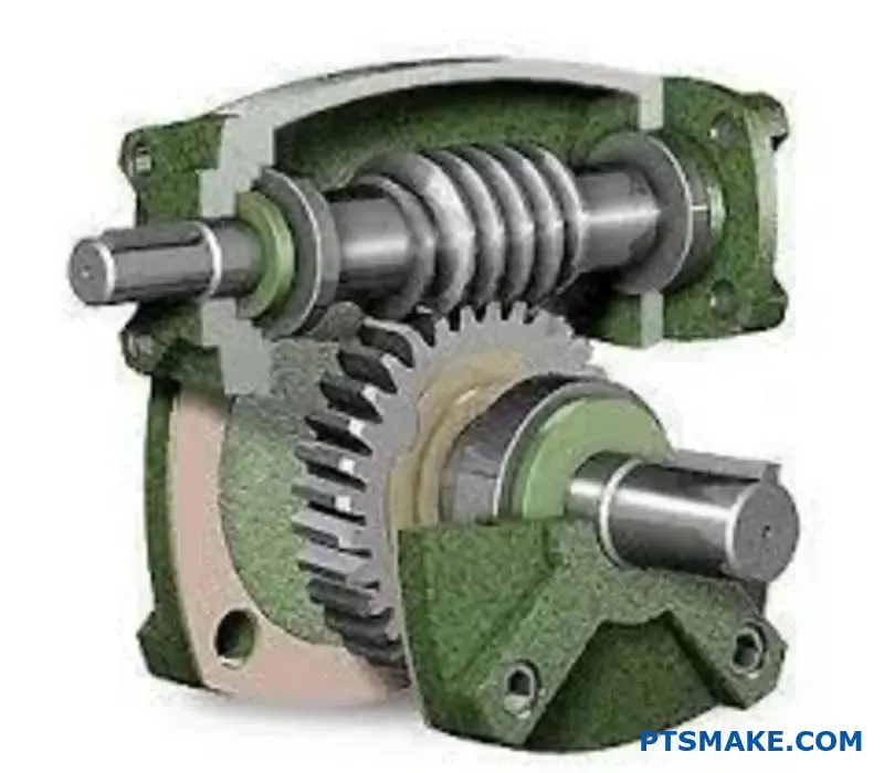
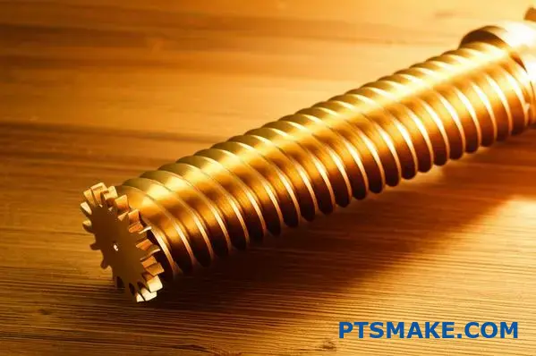
Worm gears present a puzzling challenge for engineers: they offer incredible reduction ratios and self-locking capabilities, but their efficiency often falls short of other gear types. This creates a real dilemma when you need high torque multiplication but can’t afford significant power losses.
Worm gears typically achieve 30-90% efficiency depending on design factors like lead angle, gear ratio, materials, and lubrication. Higher lead angles and lower ratios generally improve efficiency, while self-locking configurations trade efficiency for holding power.
Through my work at PTSMAKE, I’ve seen many projects where the right worm gear design made the difference between a successful application and a costly redesign. This guide breaks down the engineering principles behind worm gear efficiency and gives you practical tools to optimize your designs.
Are worm gears efficient?
The question of worm gear efficiency is common. Many engineers see them as inefficient. But this view is too simple. It overlooks their unique strengths.
The Big Trade-Off
Worm gears offer very high gear ratios. They can also be self-locking. This is something other gear types cannot easily do. So, we trade some efficiency for these special features.
A Quick Comparison
| Gear Type | Typical Efficiency | Key Advantage |
|---|---|---|
| Worm Gear | 50% – 90% | High Ratio, Self-Locking |
| Spur Gear | 94% – 98% | High Efficiency, Simple |
| Helical Gear | 94% – 98% | Smooth, Quiet Operation |
The numbers show a difference. But the application determines the best choice. It’s not just about the efficiency percentage.
Understanding Worm Gear Inefficiency
The primary reason for lower efficiency is friction. Worm gears operate with sliding contact. This is different from spur or helical gears, which use mostly rolling contact. Sliding action generates more heat and results in energy loss.
However, worm gear efficiency isn’t a single, fixed number. It varies widely. We can improve it with smart design and precision manufacturing. At PTSMAKE, we focus on these details.
Key Factors in Efficiency
Several elements impact the final performance. Getting these right is critical for any project. In our experience, material selection and lubrication are often the most important.
| Factor | Impact on Efficiency | Note |
|---|---|---|
| Lead Angle | High | Larger angles improve efficiency |
| Lubrication | High | Reduces friction and heat |
| Surface Finish | Medium | Smoother surfaces reduce friction |
| Materials | Medium | Low-friction materials help |
The design of the worm and wheel matters a lot. A higher lead angle1 reduces sliding friction, boosting efficiency. Proper lubrication creates a film between surfaces. This prevents direct metal-to-metal contact. Finally, the quality of the manufacturing, like the surface finish we achieve through CNC machining, plays a vital role in minimizing energy loss.
Worm gears are inherently less efficient due to sliding friction. However, their unique high-ratio and self-locking capabilities make them invaluable. Efficiency is not static; it is heavily influenced by design, material choice, and manufacturing precision, which can be optimized for specific applications.
How do you calculate the efficiency of a worm gear?
Calculating worm gear efficiency isn’t about one simple formula. It’s about understanding the key factors that cause energy loss. The primary source of inefficiency in these systems is sliding friction.
This friction occurs between the worm thread and the gear teeth. Therefore, several design and operational elements directly influence the final efficiency value.
Lead Angle
The lead angle of the worm is the most critical factor. A larger lead angle generally leads to higher efficiency. This is a crucial design choice we often discuss with clients at PTSMAKE.
Frictional Losses
The materials used and the lubricant’s quality also play a huge role. They determine the overall friction.
| Factor | Impact on Efficiency |
|---|---|
| Lead Angle | High |
| Lubrication | Medium |
| Surface Finish | Medium |
| Materials | Low |
To truly grasp the calculation, you need to dig deeper into these influencing variables. It’s less about plugging numbers in and more about understanding the physics at play. At PTSMAKE, we focus on optimizing these factors during the design and manufacturing stages.
The Role of Geometry and Materials
The lead angle determines the balance between sliding and rolling motion. Higher lead angles promote more efficient power transmission. Angles below 5 degrees can have very low efficiency, sometimes under 50%.
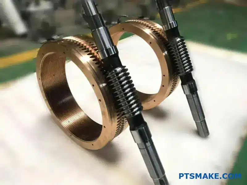
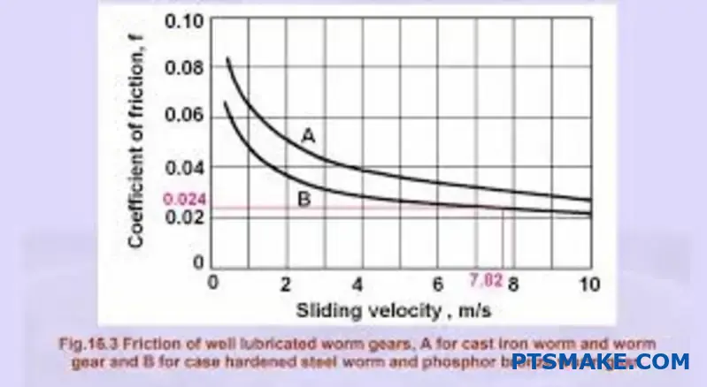
The materials for the worm and wheel are also vital. A common combination is a hardened steel worm and a bronze wheel. This pairing is chosen to minimize friction and wear. The surface finish of these components, achieved through precision machining, further reduces the coefficient of friction2.
Operational Conditions
Finally, operating conditions like speed, load, and temperature affect lubricant performance. The right lubricant creates a thin film between the surfaces, preventing direct metal-to-metal contact.
Below is a simplified view of how speed can affect efficiency.
| Rotational Speed | Typical Efficiency Trend |
|---|---|
| Low | Lower due to boundary lubrication |
| Medium | Higher as hydrodynamic film forms |
| High | May decrease due to churning losses |
Calculating worm gear efficiency requires a detailed look at the lead angle, materials, surface quality, and lubrication. These elements collectively determine the frictional losses, which are the main source of inefficiency in the system. Optimizing them is key to performance.
What are the disadvantages of worm gears?
While worm gears offer high gear ratios and self-locking features, they come with significant drawbacks. Their primary disadvantage is low efficiency. This often translates to wasted energy and higher operational costs for your machinery.
Understanding the Efficiency Problem
The main issue is the sliding contact between the worm and the wheel. Unlike other gears that use rolling contact, this sliding action creates substantial friction. This directly impacts the overall worm gear efficiency.
Efficiency Comparison
| Gear Type | Typical Efficiency |
|---|---|
| Spur Gear | 94% – 98% |
| Helical Gear | 94% – 98% |
| Bevel Gear | 93% – 97% |
| Worm Gear | 30% – 90% |
As you can see, the efficiency range for worm gears is wide and can be quite low.
The High Cost of Friction
The inherent design of a worm gear system leads to several interconnected problems. These issues stem directly from the way the components interact, making material selection and lubrication critical for performance.
Heat Generation
A major consequence of low efficiency is significant heat generation. The energy lost to friction is converted directly into heat. This can cause the lubricant to break down and may require cooling systems, adding complexity and cost.
This heat must be managed carefully. In past projects at PTSMAKE, we’ve seen overheating lead to premature failure and damage to surrounding components. It’s a critical design consideration.
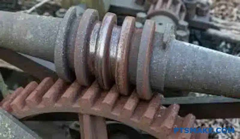
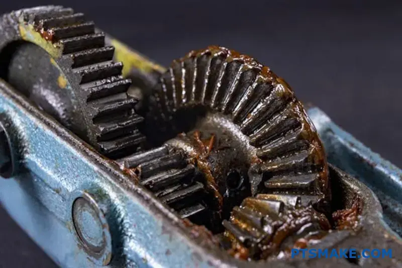
Material Wear and Tear
The intense friction also causes rapid wear, particularly on the worm wheel. The wheel is typically made from a softer material, like bronze, to reduce wear on the harder steel worm. This is by design, making the wheel a sacrificial component.
| Worm Material | Wheel Material | Wear Characteristic |
|---|---|---|
| Hardened Steel | Bronze | Good, wheel wears first |
| Hardened Steel | Cast Iron | Moderate, higher friction |
| Stainless Steel | Bronze | Good corrosion resistance |
This means you must plan for regular maintenance and replacement of the worm wheel. This is due to the high amount of sliding friction3 between the worm and the wheel. The constant rubbing action simply wears the material away over time, affecting precision.
Worm gears are powerful but inefficient. The sliding friction between components results in significant energy loss, which generates heat and causes rapid wear on the softer worm wheel. This necessitates careful thermal management and regular maintenance schedules to ensure reliable operation.
Which is better helical or worm gear?
When choosing between gears, efficiency is often the first concern. Helical gears are clear winners here. Their rolling contact design minimizes friction.
Worm gears operate on a different principle. They involve more sliding contact. This results in lower efficiency but offers unique benefits. It is not always about pure efficiency.
Key Performance Metrics
Let’s look at a high-level comparison. This helps frame the decision-making process for your specific application.
| Feature | Helical Gear | Worm Gear |
|---|---|---|
| Typical Efficiency | 95-99% | 50-90% |
| Gear Ratio Range | Low to Medium | High |
| Self-Locking | No | Yes (often) |
This table shows a fundamental trade-off. You exchange efficiency for a high gear ratio and self-locking capabilities.
A Deeper Technical Comparison
The efficiency difference stems from their basic mechanics. Helical gears mesh with a smooth, rolling action along angled teeth. This process is highly efficient.
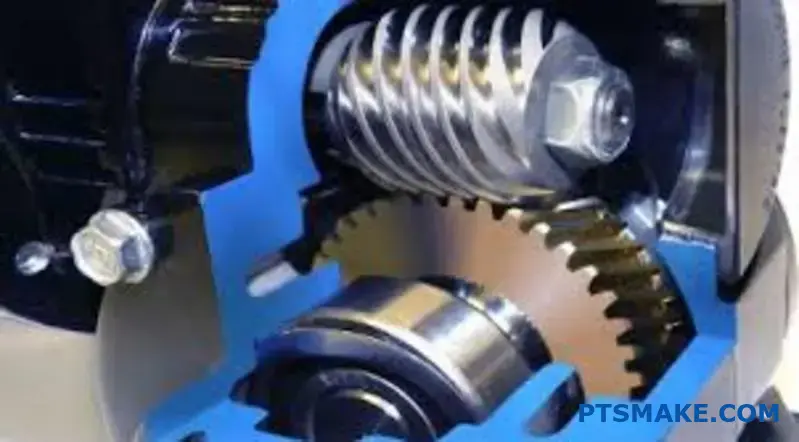
In contrast, a worm gear functions like a screw. The worm’s thread slides against the teeth of the gear. This sliding friction generates more heat and results in energy loss. The lower Worm gear efficiency is a direct result of this sliding contact.
However, this "inefficiency" creates a major advantage: self-locking. In many cases, the gear cannot drive the worm backward. This is a critical safety feature in applications like lifts and conveyors. At PTSMAKE, we often machine worm gear sets for clients who need this specific feature.
Precision and Noise
Helical gears generally operate more quietly. The gradual engagement of their angled teeth reduces vibration.
For high-precision systems, managing Backlash4 is crucial. Both gear types can be manufactured to tight tolerances, but their operational nature presents different challenges. In our past projects at PTSMAKE, we use high-precision CNC machining to minimize backlash for both systems, according to customer needs.
| Aspect | Helical Gear | Worm Gear |
|---|---|---|
| Contact Type | Rolling | Sliding |
| Noise Level | Low | Moderate |
| Backlash | Can be low | Can be low (adjustable) |
| Heat Generation | Low | High |
| Primary Advantage | Efficiency, Speed | High Ratio, Self-Locking |
Ultimately, the choice depends on your priorities.
Helical gears offer superior efficiency for high-speed applications. Worm gears provide high reduction ratios and a crucial self-locking feature in a compact form, making them ideal for specific torque-heavy tasks despite their lower efficiency. It’s a classic engineering trade-off.
What is worm gear efficiency from an energy loss perspective?
The core of understanding worm gear efficiency lies in a simple physics principle. Energy is never truly lost; it just changes form.
The Energy Conservation Equation
For any mechanical system, including worm gears, the power you put in must equal the power you get out, plus any power that is lost along the way.
Power In = Power Out + Power Loss
This isn’t just theory. It’s a quantifiable reality. An 80% efficiency rating means 20% of the input power is lost.
Quantifying Energy Loss
Let’s look at a practical example.
| Component | Power (Watts) | Description |
|---|---|---|
| Power In | 100 W | The total energy supplied to the worm shaft. |
| Power Out | 80 W | The useful work done by the worm wheel. |
| Power Loss | 20 W | Energy converted into other forms, mainly heat. |
That lost 20 watts doesn’t disappear. It becomes a problem you have to manage.
The Primary Culprit: Heat from Friction
So where does that lost energy go? In worm gear systems, the overwhelming majority is converted directly into heat. This is due to the significant sliding friction between the worm thread and the gear teeth.
This conversion is a fundamental aspect of how these gears operate. The sliding action that allows for high gear ratios is also the primary source of inefficiency.
Breaking Down Power Losses
While sliding friction is the main issue, other factors contribute to the total energy loss. We consider all of these at PTSMAKE when designing for optimal performance.
At its core, the study of tribology5 helps us understand and mitigate these effects.
| Loss Mechanism | Contribution | Primary Effect |
|---|---|---|
| Sliding Friction | ~95% of loss | Generates significant heat. |
| Bearing Friction | ~2-3% of loss | Heat generated in support bearings. |
| Lubricant Churning | ~1-2% of loss | Energy used to move oil around. |
| Seal Drag | <1% of loss | Minor friction from shaft seals. |
Understanding this breakdown is key. It shows that improving worm gear efficiency means tackling sliding friction above all else. In past projects at PTSMAKE, focusing on material selection and lubrication for this single factor yielded the greatest gains.
Understanding the principle of energy conservation is fundamental. Inefficiency in worm gears isn’t an abstract number; it’s a direct measure of input power being converted into unwanted heat, primarily due to friction between the components.
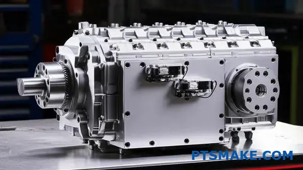
What are the primary sources of power loss in a gearbox?
Gearbox inefficiency is not a single issue. It is a result of several small energy losses combined. Understanding these sources is the first step to creating a more efficient mechanical system.
These losses can be broken down into four primary components. Each plays a role in reducing the overall output power.
Primary Sources of Loss
Here’s a quick breakdown of where that power goes.
| Loss Source | Brief Description |
|---|---|
| Gear Mesh Friction | Energy lost from teeth sliding and rolling. |
| Lubricant Churning | Resistance from gears moving through oil. |
| Bearing Friction | Losses that occur within the support bearings. |
| Seal Drag | Friction created by seals on rotating shafts. |
Each component contributes differently depending on the gearbox design and operating conditions.
To optimize a gearbox, we must analyze each source of power loss individually. The goal is to minimize their collective impact.
A Deeper Look at Each Loss
Friction at the Gear Mesh
This is often the most significant loss. As gear teeth engage and disengage, they both roll and slide against each other. This sliding action, under load, generates heat and consumes power. The gear geometry and surface finish are critical here.
Lubricant and Its Effects
Lubricant is crucial for reducing friction and wear. However, it also introduces its own form of loss. As gears rotate, they have to push through the oil in the gearbox. This effect, called lubricant churning6, takes energy.
Higher oil levels or more viscous lubricants can increase churning losses.
The Special Case of Worm Gears
In my experience with various projects at PTSMAKE, worm gears present a unique challenge. Unlike spur or helical gears that rely mostly on rolling contact, worm gears operate with almost pure sliding contact.
This makes sliding friction the dominant source of power loss by a large margin. It’s the main reason why worm gear efficiency is often much lower than other types.
| Gear Type | Dominant Loss Source | Typical Efficiency Range |
|---|---|---|
| Spur Gear | Mixed (Churning/Bearings) | 94-98% |
| Helical Gear | Mixed (Churning/Bearings) | 94-98% |
| Worm Gear | Sliding Friction | 50-90% |
Understanding this is vital when selecting a gear type for an application where efficiency is a top priority.
Total power loss in a gearbox is a sum of mesh friction, lubricant churning, and bearing or seal drag. For designs like worm gears, sliding friction at the gear mesh overwhelmingly becomes the largest single source of inefficiency.
What is the physical principle behind self-locking in worm gears?
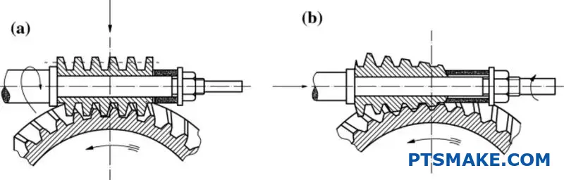
Self-locking is a key feature of worm gears. It happens when friction stops the gear from moving backward. Think of it as a one-way street for power.
This unique ability comes down to a simple relationship. The friction angle must be greater than the gear’s lead angle.
The Core Principle
When the worm tries to drive the wheel, it works fine. But when the wheel tries to drive the worm, the friction is too high. The system locks itself.
Angle Comparison
| Angle Type | Role in Self-Locking |
|---|---|
| Lead Angle | The angle of the worm’s thread. |
| Friction Angle | The angle representing frictional forces. |
This trade-off is crucial in many designs.
The Practical Trade-Off
The primary reason for self-locking is a very low lead angle. This design choice has a direct consequence: lower worm gear efficiency. The same friction that prevents back-driving also resists forward motion.
This creates a significant energy loss, often as heat. So, you get enhanced safety and control at the cost of performance. It’s a fundamental trade-off we often discuss with clients at PTSMAKE. We help them decide if the safety benefit outweighs the efficiency loss for their application.
When to Choose Self-Locking
Applications requiring load-holding are perfect candidates. Think of lifts, hoists, or conveyor belts. In these cases, preventing the load from slipping backward is a critical safety feature. The system must hold its position even when power is cut.
The static friction angle7 between the worm and the wheel surfaces is the key. When a force from the wheel attempts to rotate the worm, the resulting frictional force opposes it. If the lead angle is small enough, this friction is sufficient to completely prevent motion. This is why you can’t push your garage door up by hand if it uses a worm gear mechanism.
Self-locking in worm gears is a direct result of the friction angle being greater than the lead angle. This creates a secure, non-reversible drive but comes at the cost of lower worm gear efficiency, a critical design consideration for many applications.
Inefficiency in any mechanical system isn’t just a number. It’s lost energy. This lost energy has to go somewhere. The laws of physics dictate it converts directly into heat.
Power Loss as Heat
Every watt of power lost from inefficiency becomes a watt of heat. This is a one-to-one conversion. It’s a fundamental principle we always consider. Understanding this is key to designing robust systems.
Quantifying Heat Generation
You can calculate this heat directly. A system that is 80% efficient loses 20% of its input power. This 20% is your heat load.
| Input Power | Efficiency | Output Power | Power Loss (Heat) |
|---|---|---|---|
| 1000 W | 80% | 800 W | 200 W |
This table shows a clear example. That 200W of heat must be managed.

The Critical Role of Thermal Management
This direct conversion from lost power to heat makes thermal management essential. Especially in applications like worm gears, where efficiency can vary significantly. Ignoring heat is a recipe for premature failure.
Heat affects everything from material integrity to lubricant effectiveness. It can cause components to expand, altering critical tolerances. At PTSMAKE, we often guide clients on material selection to mitigate these thermal risks effectively.
Material and Design Impact
The choice of material and design geometry plays a huge role. Materials with high thermal conductivity8 help dissipate heat away from critical areas. This is vital for maintaining high worm gear efficiency over the long term.
In our collaborative projects, we’ve found that design modifications can significantly improve cooling.
| Feature | Impact on Heat Dissipation |
|---|---|
| Cooling Fins | Increases surface area |
| Vented Housing | Promotes airflow |
| Material Choice | Governs heat transfer rate |
For example, switching from steel to an aluminum alloy for a gearbox housing can drastically improve heat dissipation. This is a practical step to manage the heat generated by inefficiency.
Power loss in a system, measured in watts, directly converts into heat. This makes thermal management a crucial design consideration, as uncontrolled heat can lead to system degradation and eventual failure. Managing this heat is key to reliability.
What role does the coefficient of friction play in efficiency?
The coefficient of friction, or μ, is a key number. It tells us how much frictional force exists between two surfaces.
It’s a simple ratio: frictional force divided by the normal force pressing the surfaces together.
Key Influencing Factors
In gear systems, three things directly control this value. These are materials, surface quality, and lubrication. Lowering μ is a direct path to higher efficiency. This is especially true for worm gear efficiency.
| Factor | Description | Impact on Friction |
|---|---|---|
| Material Pairing | The types of metal or plastic used for the gears. | High |
| Surface Finish | The smoothness of the gear tooth surfaces. | Medium |
| Lubrication | The type and application of lubricant. | High |
To truly grasp efficiency, we must look closer at what determines the coefficient of friction. It’s not just a fixed number; we can engineer it. In my experience at PTSMAKE, managing these factors is crucial for performance.
Material Selection
Choosing the right materials is your first line of defense. Dissimilar metals, like a hardened steel worm and a bronze wheel, often have lower friction than similar metals rubbing together. This combination is a classic choice for a reason. Its unique tribological properties9 contribute to smooth operation and long life.
The Importance of Surface Finish
A smoother surface has less friction. It’s that simple. The micro-peaks and valleys on a rough surface can snag and create resistance. At PTSMAKE, we achieve ultra-smooth finishes through precision CNC machining. This directly reduces μ and boosts the efficiency of the final assembly.
Lubrication’s Critical Role
Lubrication creates a thin film between gear teeth. This film prevents direct metal-on-metal contact, drastically cutting down friction. The right lubricant for the load and speed is essential.
| Control Method | Primary Goal | Effect on Efficiency |
|---|---|---|
| Material Choice | Reduce natural adhesion and wear between surfaces. | Foundational |
| Precision Finishing | Minimize surface asperities that cause drag. | Significant |
| Proper Lubrication | Create a low-shear film separating surfaces. | Critical |
The coefficient of friction is a fundamental variable, not a constant. By carefully selecting materials, refining surface finishes, and applying correct lubrication, we can significantly reduce frictional losses and improve the overall efficiency of any mechanical system.
How does a lubricant fundamentally reduce power loss in operation?
The core job of a lubricant is simple. It separates moving surfaces. This prevents direct metal-on-metal contact, which causes high friction and wear.
Instead of solids grinding against each other, we create a fluid film.
The Three Lubrication Regimes
Understanding how this works involves three key stages, or "regimes." Each has a different level of surface separation and friction.
Boundary Lubrication
This is the first stage, often during startup. The surfaces are in frequent contact.
Mixed Lubrication
Here, a partial fluid film exists. Some surface peaks still touch, creating friction.
Hydrodynamic Lubrication
This is the ideal state. A full fluid film completely separates the surfaces.
| Lubrication Regime | Surface Contact | Friction Level |
|---|---|---|
| Boundary | High | High |
| Mixed | Partial | Medium |
| Hydrodynamic | None | Low |
The primary goal is to establish a stable hydrodynamic film. This film replaces high-friction solid contact with low-friction fluid shear. Think of it like sliding on a layer of water instead of dragging a block on concrete. The resistance drops dramatically.
Shifting Between Regimes
A system doesn’t stay in one regime. It moves between them based on speed, load, and the lubricant’s viscosity. At PTSMAKE, we design components with this in mind, ensuring they operate efficiently under various conditions.
Boundary: The Toughest Condition
Boundary lubrication happens under heavy loads or at low speeds, like during machine startup. The lubricant film is too thin to separate surfaces completely. Here, anti-wear additives are crucial. They form a protective Tribofilm10 on the metal, acting as a last defense against seizure and wear.
Hydrodynamic: The Efficiency Sweet Spot
As speed increases, the lubricant is pulled into the gap between surfaces. This motion generates enough pressure to lift one surface off the other. This is hydrodynamic lubrication. In this state, the only resistance is the internal friction of the fluid itself, which is far lower than solid friction. Achieving this regime is vital for maximizing the efficiency of components like high-speed bearings or certain gear systems.
| Operating Parameter | Effect on Lubrication Regime |
|---|---|
| Increasing Speed | Moves toward Hydrodynamic |
| Increasing Load | Moves toward Boundary |
| Increasing Viscosity | Moves toward Hydrodynamic |
Lubricants reduce power loss by replacing high solid friction with low fluid shear. The goal is to achieve a full hydrodynamic film, but systems often transition between boundary, mixed, and hydrodynamic regimes based on operating conditions like speed and load.
How do input speed and torque affect power loss components?
Understanding gearbox efficiency isn’t simple. It’s a balance of two main factors. Power loss comes from different sources. These sources respond differently to speed and torque.
The Influence of Speed and Torque
Sliding losses are mainly driven by load. This means higher torque creates more friction between gear teeth. It’s a direct relationship.
Churning losses, however, depend on speed. Faster rotation means more energy is lost just moving the lubricant around inside the gearbox.
| Loss Component | Primary Driver | Description |
|---|---|---|
| Sliding Loss | Torque (Load) | Friction from gear teeth sliding against each other. |
| Churning Loss | Speed | Energy used to displace and agitate the lubricant. |
This dual dependency is key. It explains why a gearbox’s efficiency changes so much under different operating conditions.
A Deeper Look at Loss Dynamics
Let’s break this down further. When you increase the torque, you increase the force pressing the gear teeth together. This directly elevates sliding friction and the resulting power loss. This is a major factor in worm gear efficiency.
Conversely, increasing input speed has little effect on that sliding friction. Instead, it aggressively increases churning losses. The gears have to work harder to move through the oil bath. This action creates heat and wastes energy.
Operating Scenarios
Consider two common scenarios. High-torque, low-speed applications face significant sliding losses. Think of a conveyor belt starting up.
High-speed, low-torque situations are different. Here, the primary enemy of efficiency is the churning of the lubricant. This is a form of viscous drag11.
At PTSMAKE, we help clients analyze their specific duty cycles. This ensures the gearbox is optimized for its most common operating points, not just a single peak efficiency number on a spec sheet.
| Operating Condition | Dominant Loss | Primary Cause |
|---|---|---|
| Low Speed / High Torque | Sliding | High contact force between teeth. |
| High Speed / Low Torque | Churning | High-velocity movement through lubricant. |
Understanding this trade-off is critical for designing an efficient mechanical system.
Sliding losses are tied to torque, while churning losses are linked to speed. This fundamental relationship explains why gearbox efficiency varies. Optimizing performance requires balancing these competing factors based on the specific application’s operating range.
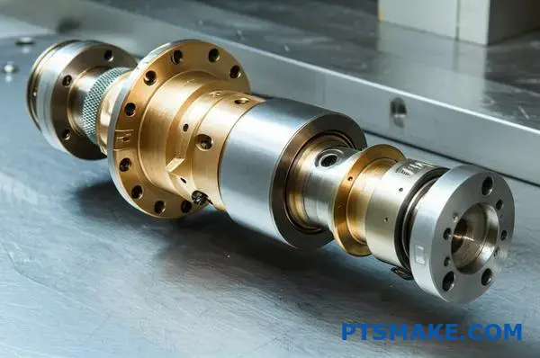
How do globoid and cylindrical worm gear designs differ in efficiency?
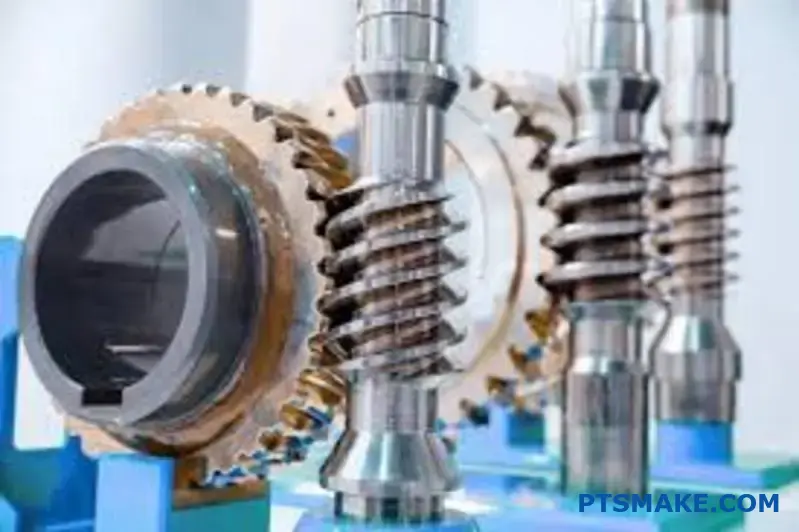
When we talk about worm gear efficiency, the design geometry is a primary factor. The two main types are cylindrical and globoid.
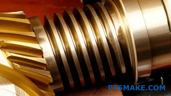
Cylindrical worms are straight, like a screw. Globoid worms, however, are curved to match the worm gear’s shape. This seemingly small difference in design creates a huge impact on performance.
Here’s a quick comparison of their basic designs:
| Feature | Cylindrical Worm | Globoid Worm |
|---|---|---|
| Worm Shape | Straight / Cylindrical | Concave / Hourglass |
| Worm Gear Shape | Standard Spur-like | Concave |
| Contact Type | Point or Line | Area / Surface |
This difference in contact is the key to understanding their efficiency.
Let’s break down the designs further. Single-enveloping sets use a standard cylindrical worm. The contact between the worm and gear is just a line or a point at any given moment. This concentrates the load on a very small area.
Double-enveloping sets, or globoid designs, are different. The worm has a concave, hourglass shape. It wraps around the worm gear. This creates a much larger contact area. More teeth are engaged at once, spreading the load significantly.
This conforming contact is the globoid’s main advantage. It directly boosts load-carrying capacity. In past projects at PTSMAKE, we’ve seen globoid systems handle much higher torques than cylindrical ones of a similar size.
This design also enhances worm gear efficiency. The larger contact area helps maintain a stable hydrodynamic film12 of lubricant between the surfaces. This robust oil film separates the metal parts more effectively. It reduces friction and wear. In our tests, this often leads to a measurable increase in operational efficiency.
| Performance Metric | Cylindrical (Single-Enveloping) | Globoid (Double-Enveloping) |
|---|---|---|
| Load Capacity | Lower | Higher |
| Contact Area | Small (Point/Line) | Large (Area) |
| Lubrication Film | Less stable | More stable & robust |
| Potential Efficiency | Good | Excellent |
Choosing between them depends on the application’s specific needs for load, efficiency, and cost.
Globoid worm gears offer superior load capacity and potential efficiency. This comes from their conforming contact, which promotes a more stable lubrication film. Cylindrical designs are simpler and often more common for general-purpose applications.
What are the key categories of factors influencing overall efficiency?
To truly grasp worm gear efficiency, we must break it down. I find it helpful to group the influencing factors into four main categories.
This systematic approach helps in analyzing and optimizing performance. It prevents overlooking critical details. Each category plays a distinct role.
Design and Geometric Factors
The initial design sets the stage for efficiency. Key parameters here are fundamental.
Material Factors
The choice of materials directly impacts friction and wear resistance over the component’s life.
Lubrication Factors
Proper lubrication is crucial for minimizing friction and dissipating heat effectively.
Operational Factors
How the gear is used in a real-world application significantly affects its performance.
Let’s delve deeper into these four areas. Ignoring any one of them can lead to unexpected performance issues down the line. A holistic view is essential for robust and efficient design.
Design/Geometric Factors
The lead angle is perhaps the single most important design choice. A higher lead angle generally leads to better efficiency. However, this often comes at the cost of a lower gear ratio, presenting a classic engineering trade-off.
The gear ratio itself also plays a role. Very high ratios often mean lower efficiency due to increased sliding contact.
Material Factors
Material selection is critical. The common pairing is a hardened steel worm with a bronze wheel. Bronze offers good lubricity and wear properties. At PTSMAKE, we pay close attention to the surface finish of machined components. A smoother finish reduces the initial Coefficient of Friction13 and break-in period.
| Factor | Impact on Efficiency |
|---|---|
| Worm Material | Hardness reduces wear |
| Wheel Material | Bronze offers low friction |
| Surface Finish | Smoother finish reduces friction |
Lubrication Factors
The right lubricant is non-negotiable. Its viscosity must match the operational speed and temperature. Additives for extreme pressure (EP) can also prevent catastrophic failure under heavy loads, preserving the gear surfaces.
Operational Factors
Finally, real-world conditions matter immensely. Efficiency is not static. It changes with speed, load, and temperature. For example, efficiency often increases with speed up to a certain point before churning losses take over.
In short, overall efficiency is a complex outcome. It is determined by the interplay between design geometry, material science, lubrication strategy, and the specific operational demands of the application. Each factor must be carefully considered.
How do common material pairings (steel/bronze) affect frictional losses?
Have you ever wondered why steel and bronze are so prevalent in worm gear systems? This isn’t by chance. It’s a classic engineering choice for a reason.
The Classic Combination
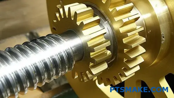
A hardened steel worm paired with a bronze wheel is the industry standard. This pairing is specifically designed for optimal performance and longevity.
Key Advantages at a Glance
This material choice directly improves worm gear efficiency. It creates a perfect balance between strength and controlled, predictable wear.
| Feature | Steel Worm | Bronze Wheel |
|---|---|---|
| Hardness | Very High | Relatively Low |
| Primary Role | Driver | Sacrificial |
| Expected Wear | Minimal | Controlled |
This strategic setup is key to minimizing friction.
Let’s break down precisely why this steel-bronze duo is so effective. It’s a masterful blend of materials science and practical, long-term design thinking.
The Role of a Sacrificial Material
The bronze wheel is designed to be a "sacrificial" component. Its relative softness means it wears down over time. This intentionally protects the more complex and expensive hardened steel worm.
In our experience at PTSMAKE, this design philosophy saves clients significant costs in maintenance and downtime. Replacing a bronze wheel is much simpler and more affordable than replacing an entire worm shaft.
Low Friction for High Performance
Steel and bronze naturally have a low coefficient of friction when they run against each other. This is absolutely critical for achieving high worm gear efficiency. Less friction means less energy is wasted as heat, allowing the system to operate cooler and more smoothly.
The Cleverness of Embeddability
Here is a brilliant, often overlooked, benefit. Any tiny wear particles or foreign debris get pressed into the softer bronze surface. This prevents them from getting trapped and grinding between the gear teeth. This process avoids a failure where severe adhesion14 could cause scoring and rapid destruction of the gear surfaces. The bronze effectively "captures" the debris, keeping the contact path clean.
The hardened steel worm and bronze wheel pairing is a proven, intelligent solution. The bronze acts as a sacrificial element, protecting the costlier steel worm. This combination provides low friction and excellent embeddability, boosting worm gear efficiency and operational lifespan.
What is the core trade-off between gear ratio and efficiency?
Let’s examine the basic geometry of worm gears. This is crucial for understanding their performance. For any given worm diameter, a higher gear ratio introduces a fundamental constraint.
The Lead Angle Constraint
A higher ratio requires the worm’s thread to have a smaller lead angle. This is not a design choice; it’s a geometric necessity.
This single factor directly impacts worm gear efficiency. A smaller angle creates more sliding friction and less effective rotational force.
| Gear Ratio | Typical Lead Angle | Potential Efficiency |
|---|---|---|
| Low (10:1) | Larger (>15°) | Higher |
| High (60:1) | Smaller (<5°) | Lower |
This inverse relationship is the heart of the trade-off. It’s a core principle we must manage in every worm gear design.
The Physics of Friction and Force
Why does a smaller lead angle reduce efficiency? It all comes down to the forces at play during the sliding contact between the worm thread and the gear tooth.
The lead angle determines how the input force is split. A large, efficient lead angle directs more of the input energy into turning the gear. Less energy is wasted as heat from friction. This is vital for better worm gear efficiency.
Force Components
Think of the force as having two jobs. One part pushes the gear tooth forward, creating output torque. The other part simply creates friction as the surfaces slide past each other.
A small lead angle makes the friction component much larger than the turning component. The material’s coefficient of friction15 is a constant factor, but the geometry dictates how much effect it has.
In past projects at PTSMAKE, we’ve had to navigate this challenge. Switching from a high-ratio design to a multi-stage system with lower ratios often provides a much better overall efficiency, even if it adds complexity.
| Aspect | Small Lead Angle (High Ratio) | Large Lead Angle (Low Ratio) |
|---|---|---|
| Force Direction | More sliding, less turning | More turning, less sliding |
| Friction Loss | High | Low |
| Heat Generation | High | Low |
| Self-Locking | Often present | Less likely |
This geometric reality is something we always discuss with clients. If you need a high ratio, you must be prepared for the corresponding drop in efficiency.
In essence, the gear ratio sets the worm’s lead angle. A higher ratio results in a smaller angle, which inherently increases sliding friction. This geometric fact creates the core trade-off between a high reduction ratio and optimal efficiency.
What practical methods can be used to measure gearbox efficiency?
Measuring gearbox efficiency is crucial. It reveals how much power is lost during operation. There are two primary, practical methods to do this.
The Direct Mechanical Method
This approach directly measures power. We use sensors on both the input and output shafts. This provides precise data for an accurate calculation.
The Indirect Thermal Method
This method estimates power loss. It achieves this by measuring heat output. Heat is a direct result of operational inefficiency. Each method has its place, and we’ll explore them further.
In-Depth Look: Mechanical Measurement
This is the most accurate method available. We install torque and speed sensors on the input and output shafts of the gearbox.
The formula is straightforward: Power = Torque × Angular Speed. By comparing the input power to the output power, we determine the efficiency.
| Measurement | Input Shaft | Output Shaft |
|---|---|---|
| Torque | Sensor T1 | Sensor T2 |
| Speed | Sensor S1 | Sensor S2 |
| Power | P_in = T1 × S1 | P_out = T2 × S2 |
Efficiency is then calculated as (P_out / P_in) * 100%. This direct approach is the gold standard for precision. Using a dynamometer16 is a common way to conduct these tests, as it provides a controlled load.
Unpacking the Thermal Method
The thermal method is an indirect approach. It operates on the principle that nearly all lost energy converts into heat. We measure the gearbox’s surface temperature rise over the ambient temperature.
This data, along with material properties, helps estimate heat dissipation, which approximates power loss. It’s less precise but great for field checks. It is useful for parts like worm gears, where friction significantly impacts worm gear efficiency. This method does not require dismantling the system.
Two primary methods exist for gauging gearbox efficiency. The mechanical method directly measures input and output power for high accuracy. The thermal method indirectly estimates power loss by measuring heat, offering a practical alternative for field assessments and diagnostics.
What future technologies could significantly improve worm gear efficiency?
The future of worm gear efficiency isn’t just about small improvements. It’s about a complete technological shift. We are moving beyond traditional metals and oils.
Exciting new fields are opening up. These include advanced coatings, smarter lubricants, and new materials. Smart, sensor-driven systems are also on the horizon.
These technologies promise to reduce friction and wear significantly. They will push the boundaries of what is possible.
| Technology Area | Current Approach | Future Innovation |
|---|---|---|
| Surface Coatings | Standard hardening | Diamond-Like Carbon (DLC) |
| Lubrication | Synthetic oils | Nanoparticle additives |
| Gear Materials | Bronze, Steel | Carbon Fiber Composites |
| Monitoring | Periodic checks | Real-time sensor feedback |
The Next Wave of Gear Technology
Looking ahead, several key areas will drive the next leap in performance. In our work at PTSMAKE, we constantly track these developments to inform our precision machining processes. It’s about anticipating what our clients in robotics and automotive industries will need next.
Super-Low-Friction Coatings
Diamond-Like Carbon (DLC) coatings are a prime example. They create an incredibly hard and slick surface. This drastically reduces the sliding friction inherent in worm drives. The result is less heat and higher efficiency.
Advanced Lubricant Additives
Imagine lubricants filled with microscopic helpers. Adding nanoparticles17 to gear oil can create a self-repairing, low-friction layer on gear surfaces. These tiny particles act like ball bearings, transforming sliding friction into rolling friction, which is much lower.
New Gear Materials
We’re also seeing a move beyond traditional metals. Carbon fiber composites and advanced polymers offer high strength with less weight. Lighter gears have lower inertia. This means they require less energy to start and stop, improving overall system responsiveness and efficiency.
| Technology | Primary Benefit | Potential Efficiency Gain |
|---|---|---|
| DLC Coatings | Reduced Friction | 5-10% |
| Nanoparticle Lubricants | Lower Wear & Friction | 3-7% |
| Composite Materials | Lower Inertia & Weight | 2-5% |
| Smart Sensors | Real-Time Optimization | 4-8% |
Smart Gearboxes
The future is intelligent. Embedding sensors directly into gearboxes allows for real-time monitoring of temperature, vibration, and lubrication quality. This data enables systems to adjust operating parameters on the fly for peak worm gear efficiency.
The next generation of worm gears will be more efficient thanks to new materials, advanced lubricants, and smart, self-optimizing systems. These technologies work together to reduce friction, wear, and energy loss, pushing performance beyond current limits.
Unlock Next-Level Worm Gear Efficiency with PTSMAKE
Ready to optimize your gearbox designs or need high-precision worm gear components? Contact PTSMAKE today for a fast, reliable quote. Let us deliver the precision, performance, and trusted partnership you need—from prototype to production. Inquire now to elevate your manufacturing results!

Learn how this key parameter influences the performance and efficiency of your worm gear drive system. ↩
Understand how this value is determined and its direct impact on gear performance. ↩
Understand how sliding friction impacts component lifespan and lubrication choices in mechanical design. ↩
Learn the technical details of gear backlash and how it impacts precision machinery. ↩
Learn how the science of interacting surfaces in motion impacts gear design and durability. ↩
Explore how lubricant choice impacts churning losses and overall gearbox efficiency in our detailed guide. ↩
Explore our guide on how this angle impacts gear material selection and performance. ↩
Discover how material choice directly influences heat dissipation and overall part lifespan in demanding applications. ↩
Explore how the science of interacting surfaces in motion can optimize your component’s performance and lifespan. ↩
Discover how these protective chemical layers prevent catastrophic wear during intense metal-to-metal contact conditions. ↩
Learn more about how fluid resistance impacts mechanical efficiency. ↩
Learn how this thin layer of lubricant is crucial for gear performance and longevity. ↩
Understand the science of friction and how it directly impacts your component’s performance. ↩
Understand how material adhesion and galling can lead to catastrophic gear failure. ↩
Discover how this key material property influences gear design and performance calculations. ↩
Understand how this device accurately measures torque and speed to calculate true mechanical power. ↩
Understand how these microscopic particles are set to revolutionize industrial lubrication and reduce operational costs. ↩