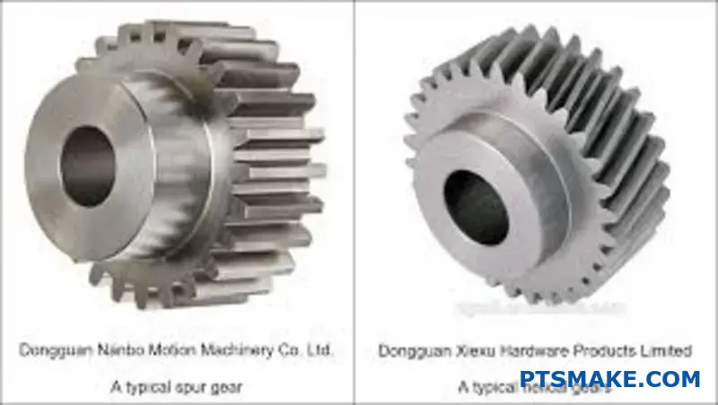
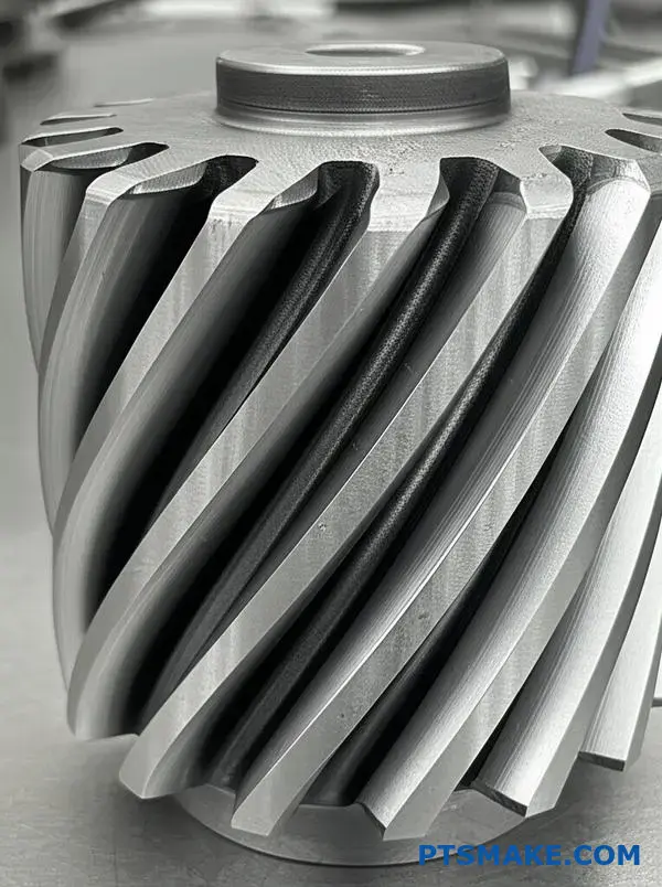
Helical gears seem complex at first glance. Many engineers struggle with understanding how the angled teeth actually work and why they’re chosen over simpler spur gears in critical applications.
Helical gears use angled teeth to create gradual, progressive contact that eliminates the sudden impacts of spur gears, resulting in quieter operation, higher load capacity, and smoother power transmission – making them essential for high-speed and precision applications.
I’ve worked with helical gears in everything from automotive transmissions to precision robotics systems. The principles behind their superior performance become clear once you understand the fundamental differences in tooth engagement. Let me walk you through the key concepts that will help you make informed decisions about when and how to use helical gears effectively.
How does a helix angle fundamentally change gear tooth contact?
Have you ever wondered why some gears are so much quieter than others? The answer often lies in the helix angle. Spur gears have straight teeth. They engage along their entire face instantly. This creates a sudden impact.
Helical gears, however, have angled teeth. This angle transforms the contact completely. Engagement starts at one end and smoothly progresses across the tooth. This gradual contact is the secret behind many helical gear advantages.
| Gear Type | Contact Method | Resulting Effect |
|---|---|---|
| Spur Gear | Instant Line Contact | Abrupt Impact, Noise |
| Helical Gear | Progressive Diagonal Contact | Smooth, Quiet Operation |
This fundamental shift from abrupt to gradual contact is what we will explore.
From Line Impact to Gradual Engagement
Spur gear teeth meet abruptly across their full width. Imagine two flat surfaces slapping together. This instantaneous line contact creates impact forces. It is the primary source of the characteristic whine you hear from some transmissions. This also puts significant stress on the tooth at once.
The Sliding Action of Helical Gears
Now, picture the angled teeth of a helical gear. As two teeth begin to mesh, contact starts at a single point on one end. As the gears rotate, this contact point sweeps diagonally across the face of the tooth.
This creates a smooth, progressive engagement. Instead of a sudden slap, it is a gentle slide. This sliding action allows for a more gradual transfer of load from one tooth to the next, which is a key principle.
Understanding Progressive Contact
The contact area is always moving. This ensures that multiple teeth are sharing the load at any given moment. Based on our tests, this distribution greatly increases the gear’s load-carrying capacity. This angled engagement does introduce a side force called axial thrust1, a factor we always account for at PTSMAKE.
| Engagement Stage | Spur Gear Contact | Helical Gear Contact |
|---|---|---|
| Start | Full line contact | Point contact at one end |
| Middle | Full line contact | Diagonal line across face |
| End | Instant disengagement | Point contact at other end |
The helix angle transforms gear tooth meshing from a harsh, instantaneous impact into a smooth, rolling action. This gradual engagement and sliding motion are responsible for quieter operation, reduced vibration, and a higher load capacity compared to spur gears.
The Core Principle: Gradual Engagement
The primary source of quietness is simple: gradual engagement. Unlike spur gears that clash along their entire tooth face at once, helical gear teeth slide into contact.
This process starts at one end of the tooth. It then moves progressively along the face until the teeth are fully engaged. This is a key helical gear advantage.
Spur vs. Helical Engagement
| Gear Type | Engagement Style | Initial Contact | Result |
|---|---|---|---|
| Spur Gear | Instantaneous | Full tooth face | High Impact, Noise |
| Helical Gear | Gradual | Point/Line contact | Smooth, Quiet |
This fundamental difference eliminates the "shock" of meshing. The load is applied smoothly, not suddenly.
The Physics of Shock and Vibration Reduction
The magic lies in the helix angle. This angle ensures that before one tooth pair disengages, the next pair has already begun to make contact. This creates a continuous, overlapping transfer of power.
This phenomenon is quantified by the contact ratio. It includes both the standard profile contact and the helical overlap2. A higher ratio means more teeth share the load at any given moment.
At PTSMAKE, we design for an optimal contact ratio. This minimizes pressure fluctuations and impact loading, which are the direct physical causes of gear noise. Instead of a sharp "bang" with each tooth mesh, you get a smooth, quiet hum.
Helix Angle’s Impact on Noise
A greater helix angle generally leads to a larger overlap and quieter operation. However, it also introduces axial thrust, a force we must manage in the overall design.
| Helix Angle | Overlap Ratio | Noise Level |
|---|---|---|
| Low (e.g., 15°) | Lower | Moderate |
| High (e.g., 45°) | Higher | Very Low |
Based on our tests, this relationship is clear. The smooth load transfer significantly dampens the vibrations that your ear perceives as noise. It’s not just smoother; it’s a fundamental reduction in vibratory energy.
The quiet operation of helical gears stems from their angled teeth. This design allows for gradual engagement, which spreads the load and prevents the impact and vibration that cause noise in spur gears.
Why can helical gears carry more load than spur gears?
Helical gears can handle more load primarily because of their angled teeth. This simple design change creates a significant performance advantage. It fundamentally alters how force is transferred between meshing gears.
The Secret is in the Angle
Unlike spur gears, the teeth on a helical gear engage gradually. The contact starts at one end of the tooth. It then progresses across the face of the tooth.
This gradual engagement is one of the key helical gear advantages.
Understanding Contact Lines
The angle effectively increases the total length of the contact line for a given gear width. More tooth surface is engaged at any time.
| Feature | Spur Gear | Helical Gear |
|---|---|---|
| Tooth Angle | Straight (0°) | Angled (Helix Angle) |
| Initial Contact | Full Line Contact | Point, then Line |
| Total Contact | Shorter Straight Line | Longer Diagonal Line |
This design distributes the load far more effectively.
Spreading the Stress
This longer contact line directly reduces stress. The load is spread over a much larger surface area. This simple fact prevents stress from building up at any single point.
With spur gears, the entire tooth width takes the load at once. This creates a high-impact shock. The stress is highly concentrated along a straight line.
Visualizing Load Distribution
Helical gears avoid this sudden impact. The load is applied and removed smoothly and gradually across the tooth.
This significantly reduces the peak Hertzian contact stress3 on the teeth. As a result, the gear can handle much higher loads without risk of failure. This also leads to a longer operational life.
In our projects at PTSMAKE, we often recommend helical gears for applications that demand both high torque and long-term reliability.
Stress Diagrams Compared
If you look at stress diagrams, the difference is clear. For a spur gear, you see a sharp, narrow band of high stress.
For a helical gear, the stress is spread out. It appears as a wider, less intense area. This difference is fundamental.
| Stress Factor | Spur Gear | Helical Gear |
|---|---|---|
| Load Application | Sudden, Instantaneous | Gradual, Progressive |
| Stress Concentration | High, Focused Peaks | Lower, Distributed |
| Risk of Pitting | Higher | Significantly Lower |
This superior stress management is why helical gears excel under heavy loads.
The angled teeth of helical gears create a longer contact line, distributing load over a larger surface. This design significantly reduces peak stress on the teeth, allowing helical gears to carry substantially more load and operate more smoothly than spur gears.
How does the ‘overlap ratio’ directly relate to smoother power transmission?
The overlap ratio is a key metric. It simply defines how many tooth pairs are in contact at any given moment.
For truly smooth power transmission, this value must be greater than one. This ensures a seamless handover. A new pair of teeth engages before the previous pair disengages.
The Significance of a High Ratio
| Overlap Ratio | Engagement | Result |
|---|---|---|
| < 1 (Spur Gears) | Intermittent | Torque Fluctuation |
| > 1 (Helical Gears) | Continuous | Smooth Power Flow |
This continuous contact is the secret behind the quiet, smooth performance we expect from high-quality gear systems. It directly reduces vibration.
The magic of helical gears lies in this continuous engagement. With an overlap ratio above one, power doesn’t just transfer; it flows smoothly from one tooth pair to the next.
This eliminates the sudden load transfers that cause noise and vibration in spur gears. Think of it as a smooth relay race rather than a series of abrupt starts and stops. One of the key helical gear advantages is this inherent smoothness.
Practical Implications
In our work at PTSMAKE, we design for an optimal overlap ratio. This ensures our clients’ machinery runs quietly and efficiently. It’s a critical detail that impacts the entire system’s performance and longevity.
The calculation itself depends on the gear’s face width and its Axial Pitch4. Essentially, a wider gear face allows for more overlap, enhancing the smoothness.
Contact Comparison
| Feature | Spur Gears | Helical Gears |
|---|---|---|
| Tooth Contact | Abrupt, full-line | Gradual, continuous |
| Load Transfer | Sudden shift | Shared and smooth |
| Vibration Level | Higher | Significantly lower |
This gradual engagement and load sharing not only reduces noise but also lowers stress on individual teeth. This often leads to a more durable and reliable gear train.
An overlap ratio greater than one is fundamental to smooth power transmission. It guarantees continuous tooth contact, which eliminates torque fluctuations, reduces vibration, and results in quieter, more reliable operation—a hallmark of well-designed helical gear systems.
Are helical gears more efficient than spur gears, and why?
When we talk about gear efficiency, the answer isn’t a simple yes or no. The meshing efficiency of helical gears is very high. It’s comparable to spur gears, often around 98-99%.
But there’s a subtle difference. The angled teeth on helical gears slide against each other. This sliding action creates more friction than the pure rolling of spur gears. This friction leads to some energy loss.
However, the main efficiency challenge comes from managing axial thrust. This is a crucial practical insight for any design engineer.
Factors Affecting Helical Gear Efficiency
| Factor | Impact on Efficiency | Explanation |
|---|---|---|
| Meshing | Very High | Smooth, gradual engagement minimizes impact losses. |
| Friction | Minor Loss | Sliding contact along the tooth face generates heat. |
| Axial Thrust | Major Loss | Requires thrust bearings, which add significant friction. |
The real efficiency story for helical gears is not just about the gears themselves. It is about the entire system. The primary source of inefficiency often comes from managing the forces the gears create.
The Role of Axial Thrust in System Inefficiency
Helical gears produce a sideways force called axial thrust5. This force pushes the gear along its shaft. To prevent this movement, we must use special bearings.
These components, like tapered roller bearings or angular contact ball bearings, are designed to handle this thrust. But in doing so, they introduce their own friction into the system.
In many applications we’ve handled at PTSMAKE, the power lost in these support bearings is greater than the power lost at the gear mesh itself.
Bearing Selection is Key
Choosing the right bearing is critical. The goal is to counteract the thrust with minimal added friction. Here’s a simple comparison based on our project experience.
| Bearing Type | Load Capacity | Frictional Loss | Application Example |
|---|---|---|---|
| Deep Groove Ball | Low Thrust | Low | Light-duty transmissions |
| Tapered Roller | High Thrust | High | Automotive differentials |
Optimizing the bearing arrangement is a core part of leveraging helical gear advantages. It ensures the system, not just the gear pair, operates at peak efficiency.
Helical gear efficiency is high, but system efficiency depends on managing axial thrust. The friction from required thrust bearings often causes more power loss than the gear mesh itself, making bearing selection a critical design factor.
What is the role of the ‘pressure angle’ in helical gears?
In helical gears, we deal with two key pressure angles. These are the normal and transverse pressure angles.
The normal pressure angle is measured perpendicular to the tooth. The transverse pressure angle is measured in the plane of rotation.
The helix angle links these two. Understanding this relationship is key. It dictates how forces are transmitted between the meshing teeth.
Force Implications
A larger pressure angle generally increases tooth strength. However, it also creates larger forces on the bearings.
Here is a simple breakdown of the relationship:
| Parameter | Description | Relationship to Helix Angle |
|---|---|---|
| Normal Pressure Angle (αn) | Measured normal to the gear tooth. | The base angle. |
| Transverse Pressure Angle (αt) | Measured in the plane of rotation. | Increases as helix angle increases. |
The pressure angle and helix angle together define the force dynamics. They determine the magnitude of forces that separate the gears and the axial thrust.
Understanding Gear Forces
When helical gears transmit power, several forces come into play. The tangential force does the useful work. But other forces are created as byproducts.
The separating forces6 push the gears away from each other. This force is directly proportional to the tangent of the transverse pressure angle. A higher angle means a stronger push. This increases the load on the bearings supporting the gear shafts.
The Role of Axial Thrust
The helix angle is responsible for creating axial thrust. This is a force that pushes the gear along its axis. While the helix angle is the direct cause, the overall load capacity, influenced by the pressure angle, affects its magnitude. One of the main helical gear advantages is smooth operation, but this thrust is a trade-off.
At PTSMAKE, we carefully analyze these interlinked parameters. We ensure the gear design can handle all resultant forces for long-term reliability.
| Angle Combination | Separating Force | Axial Thrust | Bearing Load |
|---|---|---|---|
| Low Pressure & Low Helix Angle | Lower | Lower | Lower |
| High Pressure & Low Helix Angle | Higher | Lower | Higher |
| Low Pressure & High Helix Angle | Lower | Higher | Higher |
| High Pressure & High Helix Angle | Higher | Higher | Highest |
The interplay between normal and transverse pressure angles, dictated by the helix angle, is fundamental. This relationship directly governs the separating and axial forces, which are critical considerations for bearing selection and overall system design in helical gear applications.
How do higher speeds amplify the advantages of helical gears?
At higher speeds, the difference between gear types becomes critical. Spur gears, with their straight teeth, engage abruptly.
This sudden contact creates significant impact forces. The result is excessive noise and vibration.
In contrast, helical gears mesh smoothly and gradually. Their angled teeth slide into place quietly.
This smooth engagement is one of the key helical gear advantages. It makes them ideal for high-speed machinery where performance matters most.
| Feature | Spur Gears at High Speed | Helical Gears at High Speed |
|---|---|---|
| Noise Level | High | Low |
| Vibration | Severe | Minimal |
| Wear Rate | Accelerated | Reduced |
| Operation | Harsh | Smooth |
Why Speed Is the Deciding Factor
The main issue with spur gears at high speed is dynamic loading. As teeth engage and disengage, they create an impact shock.
This happens because the entire width of the tooth makes contact almost instantly. Think of it as a series of tiny, rapid hammer blows.
These impacts generate forces far exceeding the static, calculated load on the gear. This leads to premature wear and potential failure. It also creates the characteristic whining sound of high-speed spur gears.
Helical gears solve this problem elegantly. Their angled teeth mean engagement is gradual. Contact begins at one end of the tooth and moves smoothly across the face.
This action avoids the harsh impact of spur gears. It ensures a constant, gentle transfer of power. This is particularly important at high pitch-line velocity7.
As a result, dynamic loads are significantly reduced. From our experience at PTSMAKE with high-precision applications, this translates directly to quieter operation, less vibration, and a much longer service life for the entire assembly.
| Dynamic Effect | Spur Gear Response | Helical Gear Response |
|---|---|---|
| Load Application | Instantaneous Impact | Gradual Engagement |
| Stress Peaks | High and Sharp | Low and Smooth |
| Component Life | Often Shortened | Significantly Extended |
| Suitability | Low to Medium Speed | High Speed |
At high speeds, spur gears create harsh impacts, noise, and wear. Helical gears, with their smooth, gradual meshing, eliminate these issues, proving their superiority for demanding, high-velocity applications and ensuring long-term reliability.
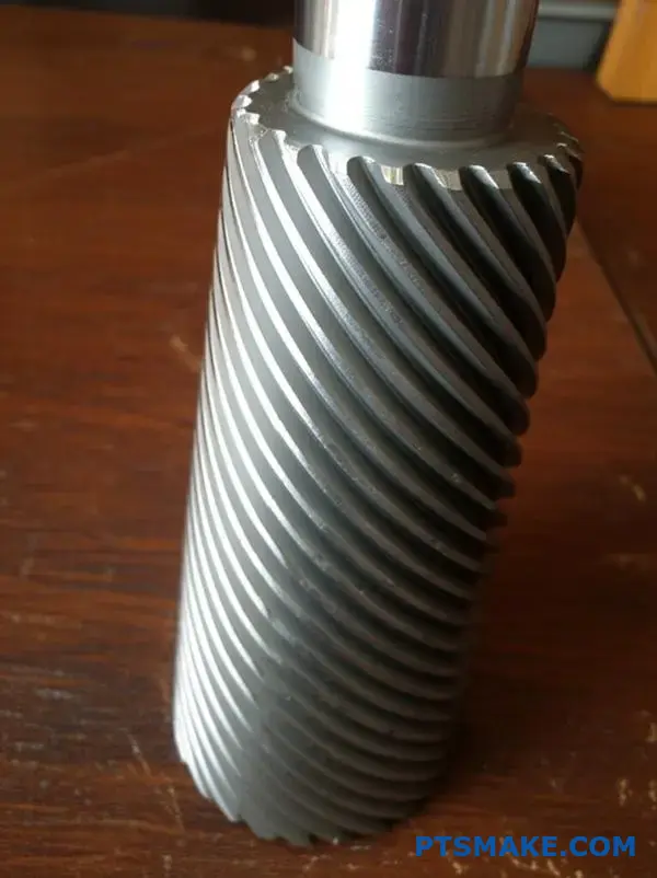
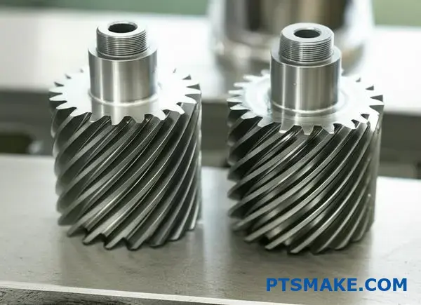
What defines the ‘hand’ of a helical gear and its importance?
Helical gears have teeth cut at an angle. This angle creates a "hand," either right or left. Think of a standard screw. A right-hand gear’s teeth slant like a right-hand thread.
This detail is not minor. It is essential. Getting the hand right ensures your gears will mesh correctly and transmit power efficiently. It is a foundational parameter in gear design.
Right vs. Left Hand
| Gear Hand | Tooth Direction | Common Analogy |
|---|---|---|
| Right-Hand | Slants up to the right | Standard screw |
| Left-Hand | Slants up to the left | Reverse-thread screw |
This simple choice dictates how two gears will interact.
The shaft arrangement determines which gear hand you need. The rules are straightforward but absolute. Following them is key to a functional gear system.
Rule for Parallel Shafts
For gears operating on parallel shafts, the rule is simple. They must have opposite hands. A right-hand gear must always mesh with a left-hand gear. There are no exceptions here.
This ensures the angled teeth engage correctly across their faces. This gradual contact is one of the main helical gear advantages, leading to smoother and quieter operation compared to spur gears.
Rule for Crossed-Axis Shafts
When shafts are crossed, usually at a 90-degree angle, the gears can have the same hand. It’s common for a right-hand gear to mesh with another right-hand gear in this setup.
This configuration changes how the teeth interact, creating more of a point contact. The choice here impacts rotational direction and the management of forces like axial thrust8. In past projects at PTSMAKE, we often use same-hand gears for crossed-axis applications.
Shaft Arrangement and Handing Rules
| Shaft Type | Required Hands | Primary Function |
|---|---|---|
| Parallel | Opposite (RH + LH) | Power transfer between parallel axes |
| Crossed-Axis | Same (RH + RH or LH + LH) | Power transfer between non-parallel axes |
Understanding this is crucial. The wrong combination will cause the system to lock up or fail. It also dictates the direction of forces, which directly impacts bearing design and housing requirements.
A helical gear’s hand is a critical design choice. For parallel shafts, opposite hands are required. For crossed-axis shafts, hands can be the same. This selection ensures proper meshing, smooth power transmission, and correct force management in your assembly.
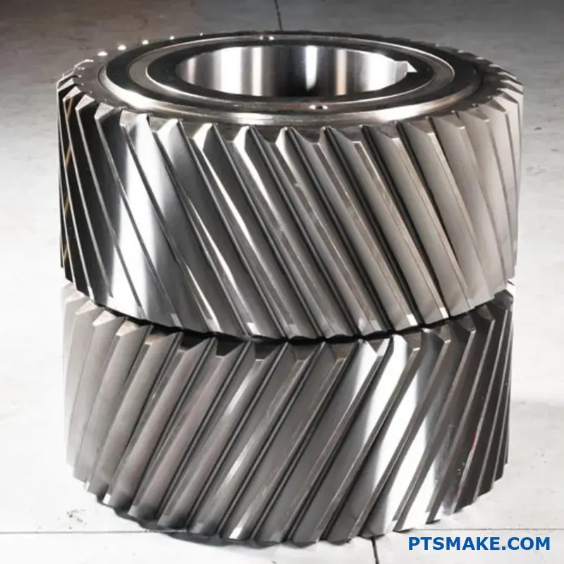
What are the key differences between single and double helical gears?
When choosing gears, a key decision is between single and double helical designs. The choice centers on managing axial thrust.
Single helical gears are efficient. However, their angled teeth create a side-to-side force. This force must be managed by thrust bearings.
Double helical, or herringbone, gears solve this. They use two opposite-hand helices. This design naturally cancels out the axial thrust.
Thrust Comparison
| Gear Type | Axial Thrust | Bearing Requirement |
|---|---|---|
| Single Helical | Generated | Requires Thrust Bearings |
| Double Helical | Self-Cancelling | Minimal Thrust Bearings |
This makes double helical gears seem superior. But there’s more to the story.
The Manufacturing Reality
One of the key helical gear advantages is smooth operation. Double helical gears enhance this by eliminating thrust. However, this comes at a significant cost. The V-shape of a herringbone gear is complex to manufacture.
Precision Machining Challenges
At PTSMAKE, we understand this complexity. Cutting the teeth requires specialized machinery. There is no room for tool runoff in the center. This precision drives up both production time and cost significantly.
In contrast, single helical gears are straightforward. They can be produced more quickly and economically. This makes them a practical choice for many applications.
Another critical difference is the inability of herringbone gears to have axial float9. This lack of movement can be a major constraint in certain gearbox designs.
Cost and Complexity Breakdown
| Feature | Single Helical | Double Helical (Herringbone) |
|---|---|---|
| Manufacturing Cost | Lower | Significantly Higher |
| Complexity | Standard | High |
| Axial Float | Possible | Not Possible |
| Thrust Management | External Bearings | Internal (Self-Cancelling) |
This trade-off is central to gear selection. You gain perfect thrust balance but sacrifice cost-effectiveness and design flexibility.
Herringbone gears offer a perfect solution for axial thrust but come with higher manufacturing complexity and cost. Single helical gears remain a cost-effective, practical choice for applications where thrust can be managed with appropriate bearings.
How do helical gears compare to bevel gears in application?
Choosing the right gear is simple. It starts with your shaft orientation. Are they parallel or do they intersect? This single question guides your initial selection.
Helical for Parallel, Bevel for Intersecting
Helical gears are the go-to for parallel shafts. Their angled teeth engage gradually. This provides a smooth, quiet operation.
Bevel gears, however, connect shafts at an angle. They are essential for changing the direction of power transmission, typically at 90 degrees.
| Gear Type | Shaft Orientation | Primary Advantage |
|---|---|---|
| Helical Gear | Parallel | Smooth and quiet operation |
| Bevel Gear | Intersecting | Changes power direction |
This fundamental difference is the first step in gear design.
But what if you need the quiet operation of a helical gear for intersecting shafts? This is where spiral bevel gears come in. They are the intersecting-axis equivalent of helical gears.
The Rise of Spiral Bevel Gears
Think of spiral bevel gears as a hybrid. They combine the angled shaft capability of bevel gears with the smooth engagement of helical gears. The teeth are curved and oblique.
This design ensures that contact begins at one end of the tooth and spreads gradually across the face. This results in less vibration and noise. It is a key reason behind the many helical gear advantages we often discuss.
Comparing Bevel Gear Types
In our projects at PTSMAKE, we often help clients choose. The decision between straight and spiral bevel gears comes down to performance needs versus cost. The imaginary pitch surface10 helps visualize how these gears mesh.
| Feature | Straight Bevel Gear | Spiral Bevel Gear |
|---|---|---|
| Tooth Shape | Straight | Curved, oblique |
| Operation | Noisier, more vibration | Smoother, quieter |
| Load Capacity | Lower | Higher |
| Common Use | Simpler, low-speed devices | High-performance transmissions |
Spiral bevel gears are ideal for demanding applications. Think of automotive differentials or high-speed industrial machinery.
The choice is clear. Use helical gears for parallel shafts. For intersecting shafts needing smooth, quiet power transmission, spiral bevel gears are the superior option. The application’s specific shaft layout dictates the best gear type.
In which applications do helical gears excel over worm gears?
Efficiency is often the bottom line. When choosing between gears, it’s a critical factor that impacts performance and operational cost.
Helical gears are champions of efficiency. Our tests show they consistently operate above 95% efficiency. This means less energy is lost as heat.
Worm gears, by contrast, are less efficient. Their sliding action creates more friction. This makes them unsuitable for applications where every watt of power counts. One of the main helical gear advantages is this superior energy transfer.
| Feature | Helical Gear | Worm Gear |
|---|---|---|
| Typical Efficiency | > 95% | 50% – 90% |
| Heat Generation | Low | High |
| Power Throughput | High | Low to Medium |
Power Throughput and Heat Management
The high efficiency of helical gears directly translates to better power throughput. They can handle heavy, continuous loads without significant energy loss. This makes them ideal for industrial machinery that runs for long periods.
In contrast, the lower efficiency of worm gears means wasted energy. This energy becomes heat. Excessive heat can degrade lubricants, accelerate wear, and may even require external cooling systems. This adds complexity and cost to the final product design. At PTSMAKE, we often advise clients on this trade-off.
However, worm gears have a unique strength: high reduction ratios in a single stage. They also possess a useful non-backdriving11 characteristic. This means the output shaft cannot drive the input shaft. This is a critical safety feature in applications like hoists or elevators, where preventing reverse motion is essential. Helical gears cannot offer this self-locking ability without additional components.
Application Suitability
| Application Need | Helical Gear Choice | Worm Gear Choice |
|---|---|---|
| High Power Transmission | Excellent | Poor |
| Minimal Energy Loss | Excellent | Fair to Poor |
| High Gear Reduction | Requires multiple stages | Excellent (single stage) |
| Self-Locking Feature | No | Yes |
Helical gears are superior for high-power, continuous applications where efficiency is key. While less efficient, worm gears are unmatched for high-ratio reduction and applications requiring their unique self-locking capability, preventing back-driving.
What are the common materials used for practical helical gear applications?
Choosing the right material for helical gears is critical. It determines the gear’s strength, lifespan, and overall performance. The wrong choice leads to premature failure and costly downtime.
Your application’s demands dictate the best material. We can group the common choices into three main categories. Each serves a distinct purpose.
High-Load Applications
For the toughest jobs, case-hardened steels are the standard. Think automotive transmissions or industrial gearboxes. They handle extreme stress and impact.
Moderate-Load Applications
Through-hardened steels work well for moderate loads. They offer a good balance of strength and cost. You find them in machinery and power tools.
Low-Load Applications
Plastics are perfect for light-duty, quiet operation. Applications include office equipment and consumer electronics.
Here is a quick overview:
| Material Category | Common Examples | Primary Use Case |
|---|---|---|
| Case-Hardened Steel | 8620, 9310 | High-load, high-impact |
| Through-Hardened Steel | 4140, 4340 | Moderate, consistent load |
| Plastics | Delrin, Nylon | Low-load, low-noise |
Let’s explore these material choices in more detail. Selecting the correct one is essential to achieving key helical gear advantages like smooth, quiet power transmission.
The Power of Case-Hardened Steels
Case-hardened steels, such as 8620 and 9310, are industry workhorses. The process creates a very hard outer surface while keeping the core ductile and tough. This dual nature is perfect for handling shock loads.
The hard case resists wear and surface fatigue. The tough core absorbs impacts without fracturing. This process also creates beneficial Residual Compressive Stress12 just below the surface, which significantly improves fatigue life. While more expensive, their durability is unmatched for critical applications.
Through-Hardened Steels: The All-Rounder
Steels like 4140 and 4340 are hardened uniformly throughout the material. This provides good strength and toughness from surface to core. They are less complex to heat-treat than case-hardened steels.
This makes them a cost-effective solution for applications with steady, moderate loads. They are easier to machine after heat treatment compared to case-hardened steels. In many projects at PTSMAKE, 4140 is a popular choice for its excellent balance.
Plastics: The Quiet Achievers
When noise and weight are concerns, plastics like Delrin (Acetal) and Nylon are excellent. They are naturally self-lubricating and dampen vibrations effectively. This results in very quiet gear operation.
They are ideal for printers, medical devices, and other low-torque systems. While they can’t handle heavy loads, their low cost and corrosion resistance make them perfect for specific environments.
| Material | Key Performance Trait | Relative Cost |
|---|---|---|
| Case-Hardened Steel | Highest strength, wear resistance | High |
| Through-Hardened Steel | Good strength, machinability | Medium |
| Plastic (Delrin/Nylon) | Low noise, self-lubricating | Low |
Material selection is a balance of performance, life, and cost. Case-hardened steels offer maximum durability for high-stress roles, while plastics provide quiet, low-cost solutions for light-duty applications. Through-hardened steels are the versatile middle ground.
What key parameters are in a typical helical gear specification sheet?
A helical gear specification sheet is the blueprint for manufacturing. It communicates the precise design intent. For junior engineers, mastering these terms is the first step.
Understanding this data sheet is crucial. It ensures the final part meets all performance, reliability, and assembly requirements. Getting it right avoids costly errors.
Below are the essential parameters we’ll cover. Each one plays a critical role in the gear’s function.
| Parameter | Function |
|---|---|
| Module / Pitch | Defines tooth size |
| Helix Angle & Hand | Determines rotational smoothness |
| Material & Treatment | Affects strength and lifespan |
| Quality Standard | Guarantees precision |
To truly specify a helical gear, you must understand its core language. These parameters are not just numbers; they define the gear’s behavior and suitability for an application.
Foundational Geometric Parameters
The most basic parameters define the gear’s size and shape.
Module or Diametral Pitch (DP): This defines the size of the gear teeth. Module is the metric standard (mm per tooth), while DP is imperial (teeth per inch). They are inversely related.
Number of Teeth: A simple count, but it directly impacts the gear ratio and overall diameter.
Helix Angle and Hand: The angle of the teeth relative to the gear’s axis. This angle allows for gradual tooth engagement, which is one of the key helical gear advantages. "Hand" specifies the direction of the angle: right or left.
Performance-Defining Parameters
These specs determine how the gear will perform under load.
Pressure Angle: This is the angle of force transmission between meshing teeth, commonly 20 degrees. It influences tooth strength and contact efficiency.
Face Width: The width of the gear tooth along the axis. A wider face increases the contact area, improving load capacity.
Material and Heat Treatment: The choice of material, like alloy steel, dictates the gear’s strength. Heat treatments, such as carburizing13, further enhance surface hardness for wear resistance while maintaining a ductile core.
| Treatment | Primary Benefit |
|---|---|
| Carburizing | High surface hardness |
| Nitriding | Good wear resistance |
| Through Hardening | Uniform core strength |
Quality Standard: Standards like AGMA or ISO define the manufacturing tolerances. An AGMA Q10, for example, specifies a high level of precision for demanding applications.
Mastering these essential parameters is foundational. It transforms a list of numbers into a clear manufacturing instruction, ensuring the final helical gear performs exactly as designed. This knowledge is key to successful sourcing and engineering.
How do lubrication requirements differ from spur gears?
At first glance, lubricating helical and spur gears seems the same. Both need oil to reduce friction and dissipate heat.
However, the design of helical gears introduces a critical difference. Their angled teeth create a sliding motion as they mesh.
This sliding action generates significantly more localized heat. This factor is crucial when selecting the right lubricant. It is a key consideration for realizing long-term helical gear advantages.
Lubrication Factor Comparison
| Feature | Spur Gears | Helical Gears |
|---|---|---|
| Primary Contact | Rolling | Rolling & Sliding |
| Heat Generation | Moderate | High (Localized) |
| Lubricant Stress | Lower | Higher |
The Impact of Sliding on Lubrication
The continuous sliding motion between helical gear teeth puts enormous stress on the lubricant’s protective film. This is fundamentally different from the primarily rolling contact found in spur gears.
This intense pressure and friction can quickly break down a standard lubricant. When the film fails, it results in direct metal-to-metal contact, leading to scoring, pitting, and eventual gear failure. This is why a one-size-fits-all approach to gear lubrication doesn’t work.
The Need for Specialized Lubricants
For helical gears, especially in high-torque or high-speed applications, we must use lubricants with higher film strength. This property ensures a robust, protective layer is maintained between the gear teeth, even under intense pressure.
In the most demanding projects at PTSMAKE, we often specify lubricants containing Extreme Pressure (EP) additives14. These compounds chemically react with the metal surfaces under heat and pressure.
This reaction forms a sacrificial, soap-like film. This layer prevents catastrophic welding and scoring if the primary oil film is momentarily breached.
Lubricant Properties for Helical Gears
| Lubricant Property | Importance for Helical Gears | Why It’s Needed |
|---|---|---|
| Film Strength | High | Resists breakdown from sliding pressure. |
| EP Additives | Critical (High Load) | Prevents scoring during metal contact. |
| Thermal Stability | High | Manages localized heat from friction. |
The sliding action in helical gears creates more heat and pressure than spur gears. This requires lubricants with superior film strength and, for heavy-duty use, Extreme Pressure (EP) additives to prevent premature wear and ensure reliable operation.
How does one design a housing to properly support a helical gear set?
When designing a housing for helical gears, stiffness is not a recommendation; it is an absolute requirement. The housing forms the backbone of the entire assembly.
It must be rigid enough to maintain precise shaft alignment under all operating loads. This includes both radial forces and the significant axial thrust unique to helical gears. Any flex can lead to immediate problems.
Critical Load Paths
A stiff housing provides a solid path for forces. It directs them from the gears, through the bearings, and into the machine frame safely.
Key Stiffness Considerations
| Force Type | Primary Challenge | Consequence of Low Stiffness |
|---|---|---|
| Radial Load | Shafts trying to move apart | Misalignment, edge loading on teeth |
| Axial Thrust | Shafts trying to move sideways | Bearing failure, gear shifting |
A lack of housing stiffness is a primary cause of premature gear failure. Even microscopic deflection under load starts a destructive chain reaction.
When the housing flexes, the shafts fall out of alignment. This means the gear teeth no longer mesh across their full face width as intended by the design.
The Cascade of Failure
Instead, the load becomes focused on a small area of the tooth, often at the very edge. This creates immense localized pressure and high Stress concentration15. The result is rapid pitting, accelerated wear, and eventually, tooth fracture.
The housing’s role in managing axial thrust is just as critical. It must provide an unyielding load path for these forces into the machine frame. If this path flexes, the entire gear and shaft assembly can shift, destroying the designed contact pattern.
Achieving this rigidity is essential to realizing the full potential of helical gear advantages, such as quiet and smooth operation.
Deflection and Its Consequences
| Deflection Type | Immediate Effect | Ultimate Failure Mode |
|---|---|---|
| Bending | Shaft Misalignment | Pitting, Tooth Breakage |
| Twisting | Skewed Gear Mesh | Uneven Wear, Noise |
| Axial Flex | Gear Axial Movement | Bearing Overload, Galling |
In summary, a housing’s stiffness is non-negotiable. It must prevent deflection from both radial and axial loads to maintain gear alignment. A rigid housing is the foundation for a durable and reliable helical gear system.
Analyze the gearbox of an electric vehicle: Why are helical gears used?
Let’s apply this to a modern case study: the EV gearbox. Electric vehicles create a unique environment for gears.
Their motors spin at incredibly high speeds. This presents a major challenge for the transmission system.
The High RPM Challenge
EV motors can easily surpass 15,000 RPM. Gears must handle these speeds reliably. Helical gears are designed for this high-speed capability.
The Silence Problem
Without a loud combustion engine, other noises are very noticeable. Gear whine can become the dominant sound, affecting the driving experience.
| Feature | Internal Combustion Engine (ICE) | Electric Vehicle (EV) |
|---|---|---|
| Primary Noise | Engine Combustion & Exhaust | Motor & Gearbox Whine |
| Typical RPM | 1,000 – 7,000 | 0 – 20,000+ |
| Key Gearbox Goal | Manage Torque Across Gears | High-Speed Reduction & Quietness |
For an electric vehicle, the quietness and high-speed performance of helical gears are not just advantages. They are essential requirements.
Matching Motor Speed and Driver Expectation
The core job of an EV gearbox is single-speed reduction. It must efficiently step down the motor’s high RPM to a usable wheel speed.
The smooth, gradual engagement of helical gear teeth is perfect for this task. It minimizes vibration and power loss at speeds where spur gears would be too noisy and inefficient. The high contact ratio16 is a significant factor in this performance.
Engineering for a Quiet Ride
In past projects at PTSMAKE, we’ve seen how critical noise reduction is for our automotive clients. The driver of a premium EV expects a near-silent cabin.
One of the key helical gear advantages is its inherent quietness. The angled teeth slide into contact rather than meshing abruptly. This prevents the high-pitched whine common with other gear types. Achieving this level of quiet requires extreme manufacturing precision.
| Helical Gear Advantage | EV-Specific Requirement |
|---|---|
| High-Speed Capability | Matches extreme motor RPMs effectively. |
| Quiet Operation | Eliminates gear whine in a silent cabin. |
| Smooth Power Transfer | Provides a seamless driving experience. |
| High Load Capacity | Handles the instant torque from electric motors. |
In our experience, the final performance is as much about the manufacturing as the design. High-precision CNC machining is crucial to producing gears that meet the tight tolerances required for EV applications.
For EVs, the high-speed and low-noise characteristics of helical gears are critical. They directly address the challenges of high motor RPMs and the need for a quiet cabin, making them a fundamental requirement for modern electric drivetrains.
Design a gear train for a specific power, speed, and ratio.
Let’s put theory into practice. A common task is designing a gear set for specific operational needs. This exercise combines our previous discussions into a real-world scenario.
We will tackle a simplified design challenge. The goal is to see how initial requirements translate directly into gear specifications and force calculations.
The Design Challenge
Here are the initial parameters for our single-stage gear reduction system.
| Parameter | Value |
|---|---|
| Motor Power | 10 kW |
| Motor Speed | 3000 RPM |
| Gear Ratio | 3:1 |
Our task is to select key gear parameters. We’ll then calculate the resulting forces to help with bearing selection.
Step 1: Choosing Gear Type and Initial Parameters
For this application, we’ll use helical gears. The key helical gear advantages are smoother power transmission and quieter operation, which are often critical requirements in precision machinery.
Based on experience from past projects at PTSMAKE, we can start with some initial assumptions for the design.
| Parameter | Assumed Value | Justification |
|---|---|---|
| Module (m) | 2.5 | A common size for this power level. |
| Helix Angle (β) | 15 degrees | Balances efficiency and axial load. |
| Pinion Teeth (Zp) | 22 | Good starting point to avoid undercutting. |
| Gear Teeth (Zg) | 66 | To achieve the 3:1 ratio (Zg = Zp * 3). |
Step 2: Calculating Forces
Now, we calculate the forces acting on the gears. This is crucial for verifying the design and selecting other components. First, we find the tangential force (Ft) on the pinion.
The calculation must confirm the gear teeth can handle the load. We need to ensure the design does not exceed the material’s allowable bending stress17.
With the tangential force known, we can find the axial thrust (Fa).
- *Axial Thrust (Fa) = Tangential Force (Ft) tan(β)**
This axial thrust is a critical value. It directly influences the type of bearings we must select, such as tapered roller bearings, to support the shaft.
This practical exercise demonstrates the core process. We translate top-level requirements like power and speed into concrete design parameters and critical force calculations needed for robust component selection.
How does thermal expansion affect a helical gear system’s performance?
Thermal expansion isn’t just about the gears themselves. It’s a system-wide issue. When a machine operates, heat causes every component to grow slightly. This includes shafts, bearings, and the housing.
The Bigger Picture
This expansion can seem minor. But in precision systems, tiny changes have big consequences. The careful alignment and spacing designed into the system can be quickly compromised.
System-Level Impact
Consider how different materials expand at different rates. This can create stress and misalignment.
| Component | Material Example | Expansion Effect |
|---|---|---|
| Shaft | Steel | Increases in length and diameter |
| Housing | Aluminum | Expands more than steel, changing clearances |
| Bearings | Steel | Tighter fit on shaft, looser in housing |
These shifts directly impact gear performance, leading to noise and wear.
Thermal expansion creates a domino effect. As components heat up and expand, the precise geometry of the gear system begins to change. This is a critical factor we always consider in design consultations at PTSMAKE.
Shaft and Housing Expansion
Shafts can lengthen and expand radially. Housings also grow, changing the distance between bearing mounts. This directly alters the shaft’s alignment, causing the gear mesh to shift from its optimal position.
An improperly aligned gear set will not exhibit the typical helical gear advantages, such as quiet operation. Instead, it will generate noise and vibration.
Impact on Backlash and Contact
As the system expands, the center distance between gears can change. This directly affects backlash, the small clearance between mating teeth. Too little backlash can cause binding and overheating. Too much can lead to impact loads and tooth wear.
Maintaining the correct contact pattern across the tooth face is crucial. Thermal expansion can concentrate the load on one part of the tooth. This leads to premature failure. In high-precision robotics and aerospace applications, we must model these thermal effects. This ensures the correct contact pattern and bearing preload18 are maintained throughout the operational temperature range.
| Parameter | Ideal State (Cold) | Operational State (Hot) | Consequence |
|---|---|---|---|
| Shaft Alignment | Perfect | Misaligned | Uneven tooth load, noise |
| Backlash | Optimal | Reduced or Increased | Binding or impact loads |
| Contact Pattern | Evenly Distributed | Concentrated | Localized wear, failure |
Thermal expansion affects the entire gear assembly, not just the gears. It can alter shaft alignment, backlash, and contact patterns. For high-precision applications, these effects must be accounted for during the initial design phase to ensure reliable performance.
What are the challenges of using helical gears in planetary systems?
Using helical gears in planetary systems is a double-edged sword. While they offer quiet, smooth operation, they introduce complex axial forces.
This isn’t a single force but an interacting system. The sun, planet, and ring gears all experience these forces.
This complicates bearing design for the planet gears. It also requires careful management to ensure proper load sharing among all planets.
| Component | Key Challenge from Axial Force |
|---|---|
| Sun Gear | Requires robust thrust bearing support. |
| Planet Gears | Bearings must handle combined radial and axial loads. |
| Ring Gear | Axial positioning is critical for force balance. |
The Complex Interaction of Axial Forces
The helix angle on the gear teeth is the source of the axial force. In a planetary set, these forces must be carefully balanced. The thrust on the sun gear is countered by the thrust on the planet gears.
This interaction creates a complex load environment. If not managed, it can lead to component misalignment and uneven wear.
A New Burden on Bearings
With spur gears, planet bearings mainly handle radial loads. This allows for simpler bearing solutions.
However, helical gears introduce a significant axial thrust19. This forces the use of more complex bearings. For example, tapered roller bearings are often needed.
These bearings can handle combined loads but are often larger. They can also add cost and complexity to the assembly.
The Load-Sharing Problem
Proper load sharing is fundamental to a planetary gear system’s longevity. Each planet should carry an equal portion of the load.
Unmanaged axial forces can cause the planet gears to tilt slightly. This disrupts the balance, forcing one or two planets to carry more of the load. This imbalance accelerates wear and can lead to early failure.
| Feature | Spur Gear Planet | Helical Gear Planet |
|---|---|---|
| Primary Load | Radial Only | Radial + Axial |
| Bearing Type | Simple (e.g., Needle Roller) | Complex (e.g., Tapered Roller) |
| Load Sharing | Easier to Balance | Requires Precise Axial Control |
In essence, the axial forces from helical gears create a system-wide challenge. This complicates bearing selection and makes equal load distribution a critical design and manufacturing task. Careful engineering is required to manage these interacting forces effectively.
What future trends will impact helical gear design and application?
The future of helical gears is exciting. We’re moving beyond traditional steel. New materials and manufacturing methods are changing everything.
Advanced Materials on the Horizon
Think composites and advanced alloys. These materials are lighter yet stronger. They offer better performance under extreme conditions. This pushes the known helical gear advantages to new limits.
The Manufacturing Revolution
Techniques like 5-axis CNC grinding are key. They allow for incredibly precise and complex tooth profiles. This directly improves gear efficiency and reduces noise.
| Feature | Traditional Steel | Future Materials (e.g., Composites) |
|---|---|---|
| Weight | Heavy | Lightweight |
| Strength | High | Very High (per unit weight) |
| Corrosion Resistance | Varies | Excellent |
These trends are not just theories. They are actively shaping the next generation of gear systems.
We’re seeing a push for gears that are not only stronger but also smarter. The goal is to maximize power density, efficiency, and operational life, which are core helical gear advantages.
Specialized Surface Coatings
Friction and wear are major enemies of gears. New coatings, like diamond-like carbon (DLC), create ultra-low friction surfaces.
In our testing, these coatings can significantly extend a gear’s service life. They also reduce the energy lost to heat. This means more efficient power transmission.
Smart Gears with Integrated Sensors
The next big leap is embedding sensors directly into gears. These sensors monitor temperature, vibration, and stress in real-time.
This technology turns a simple mechanical part into a data-gathering component. It enables predictive maintenance, preventing failures before they happen. This is a game-changer for reliability. The goal is to increase the power density20 of the entire system.
| Technology Trend | Primary Benefit | Application Impact |
|---|---|---|
| 5-Axis CNC Grinding | Higher Precision | Quieter, more efficient operation |
| Specialized Coatings | Reduced Friction/Wear | Longer lifespan, less energy loss |
| Integrated Sensors | Condition Monitoring | Predictive maintenance, higher reliability |
At PTSMAKE, we leverage advanced 5-axis CNC to prepare for these shifts. It ensures our parts meet the tight tolerances these new applications demand.
Future helical gears will be lighter, stronger, and smarter. Trends like advanced materials, precision 5-axis grinding, specialized coatings, and integrated sensors are pushing performance boundaries. These innovations will enhance efficiency, power density, and overall system reliability.
Unlock Helical Gear Advantages with PTSMAKE Precision
Ready to elevate your manufacturing with high-precision helical gears and components? Contact PTSMAKE now for a fast, detailed quote and experience our next-generation CNC machining and injection molding expertise—trusted by top global brands. Let’s collaborate to exceed your performance and quality expectations!

Discover how this force influences bearing selection and overall system design for optimal performance. ↩
Understand the engineering principles behind helical overlap and how it is optimized for quiet, efficient gear systems. ↩
Explore how surface contact stress is calculated and its impact on gear design and longevity. ↩
Learn how this dimension is critical for calculating gear performance and ensuring smooth operation. ↩
Understand how this force impacts your gear system’s performance and bearing requirements. ↩
Learn how these forces affect gear design and bearing selection. ↩
Discover how this metric is critical for gear performance and design in high-speed machinery. ↩
Learn more about how this force is generated and its impact on bearing selection and overall system design. ↩
Learn why this small amount of axial movement is critical for some gear system alignments. ↩
Explore the concept of gear geometry and how it impacts meshing and overall efficiency. ↩
Learn how this self-locking feature prevents reverse motion in machinery. ↩
Discover how this internal stress enhances gear fatigue life and prevents cracks. ↩
Learn how this surface hardening process improves gear durability and wear resistance. ↩
Understand how these chemical additives provide crucial protection for your gears under intense operating conditions. ↩
Learn how localized high stresses can cause component failure, even when overall loads seem safe. ↩
Discover how this key gear metric impacts noise levels, strength, and the overall smoothness of power transmission. ↩
Learn how bending stress analysis ensures your gear teeth are strong enough for the job. ↩
Understand how preload is critical for maintaining system accuracy and preventing premature wear. ↩
Explore how axial thrust impacts gear design and bearing selection for optimal performance. ↩
Learn how increasing this key metric can reduce the size and weight of your designs. ↩