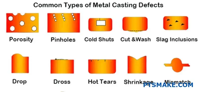
Metal casting defects cost manufacturers millions each year. Parts fail quality inspections, delivery schedules slip, and relationships with customers suffer when casting processes go wrong.
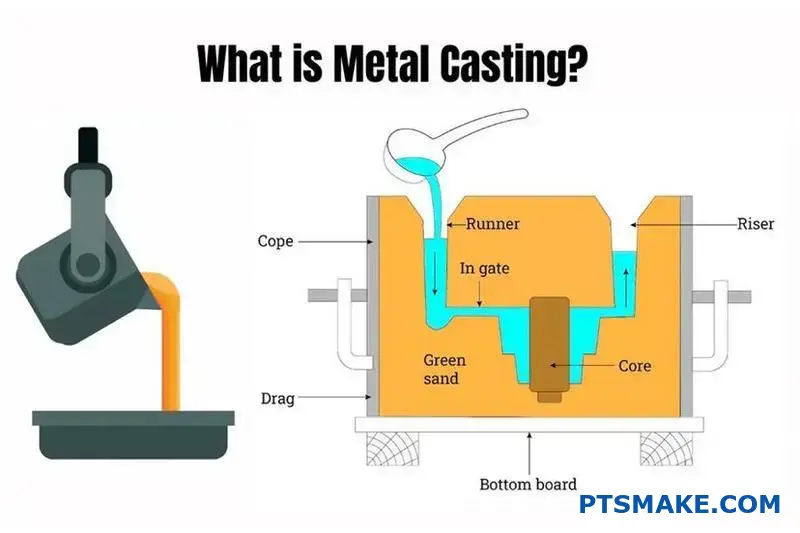
Metal casting is a manufacturing process where molten metal is poured into a mold cavity to create parts. This guide covers 14 key processes, material selection, defect prevention, and cost optimization strategies to help you achieve consistent, high-quality results from prototype through production.
Over my years at PTSMAKE, I’ve worked with engineers who needed practical solutions for casting challenges. This guide breaks down complex processes into actionable steps you can apply immediately to improve your casting operations and reduce costly mistakes.
What are the key metal casting processes and their selection criteria?
Choosing the right metal casting process is critical. This decision directly affects your final part’s quality, cost, and delivery schedule. It’s a foundational step for success.
We often help clients navigate these choices. Let’s compare three primary methods to simplify your decision.
Core Casting Processes at a Glance
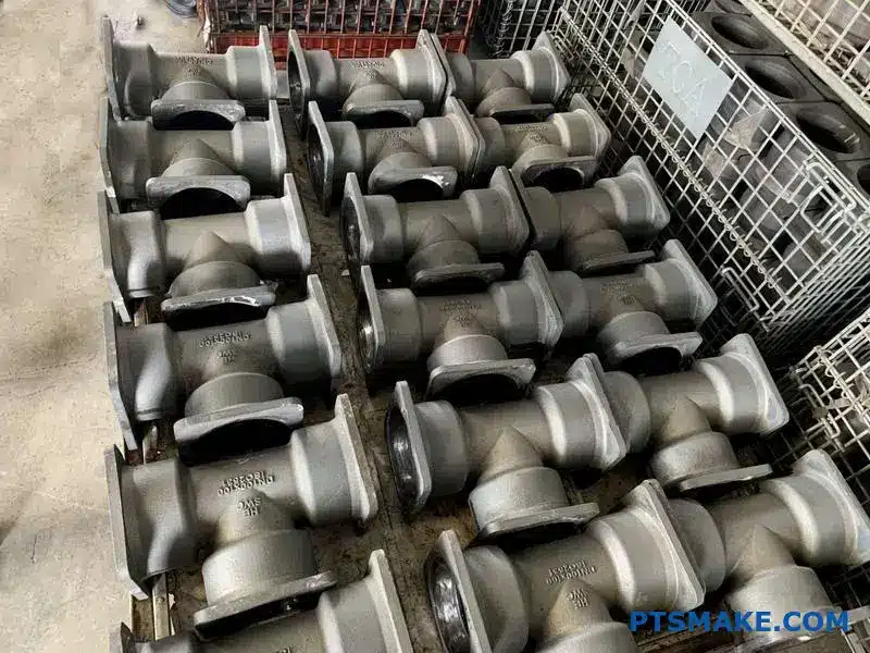
Sand, investment, and die casting are popular choices. Each serves a different purpose.
| Process | Best For | Complexity |
|---|---|---|
| Sand Casting | Large parts, low volume | Low |
| Investment Casting | Complex shapes, high finish | High |
| Die Casting | High volume, precision | Medium |
Evaluating Key Selection Criteria
Selecting the right method requires a detailed look at your project’s specific needs. Let’s break down the most important factors.
Material Compatibility
Sand casting works with almost any metal. This includes high-temperature steel and iron. Die casting is limited to non-ferrous alloys like aluminum and zinc. Investment casting offers a good middle ground.
Production Volume and Cost
Die casting has high initial tooling costs. But it offers the lowest cost per part for high volumes. Sand casting is cheap for prototypes or low volumes. The tooling is inexpensive. Investment casting sits in between.
This is where you balance initial investment against long-term production savings. A common issue across processes is internal voids, or porosity1, which can affect part integrity and increase scrap rates if not controlled.
Part Size and Finish
For very large components, sand casting is often the only option. Investment casting excels at creating small, intricate parts with an excellent surface finish, reducing the need for secondary machining.
Let’s organize this in a decision matrix. This will help you visualize the trade-offs.
| Criteria | Sand Casting | Investment Casting | Die Casting |
|---|---|---|---|
| Material Choice | Very Wide | Wide | Limited (Non-ferrous) |
| Production Volume | Low to Medium | Low to Medium | High |
| Part Size | Large | Small to Medium | Small to Medium |
| Surface Finish | Rough | Excellent | Good to Excellent |
| Unit Cost (High Vol.) | High | Medium | Low |
Choosing the right metal casting process involves a trade-off. You must balance material, volume, size, finish, and cost. This decision matrix provides a clear starting point for evaluating sand, investment, and die casting for your specific application.
What is the family of common ferrous metal casting alloys?
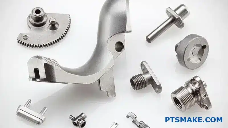
Ferrous alloys are the workhorses of metal casting. They are primarily iron-based materials.
Their properties depend heavily on carbon content and form. We mainly work with four common types.
These include gray iron, ductile iron, malleable iron, and steel castings. Each has unique strengths. This makes them suitable for different jobs. Choosing the right one is key.
Ferrous metal casting offers a wide range of options. Each alloy serves a specific purpose, and making the right selection is critical for performance and cost.
Gray Iron: The Machinability Champion
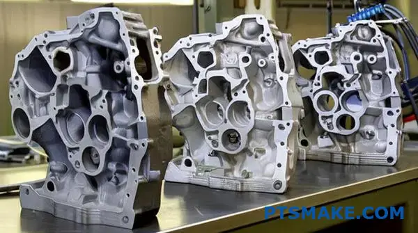
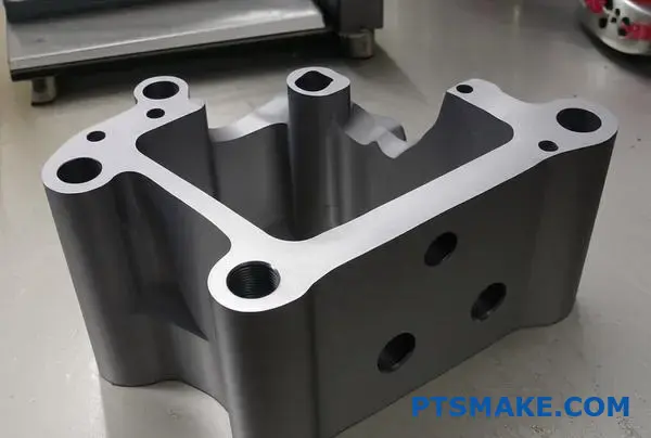
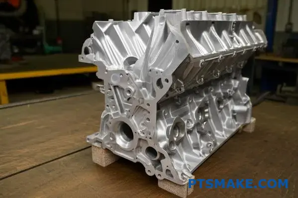
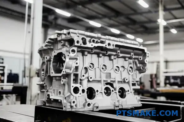
Gray iron contains carbon as graphite flakes. This structure, while making it brittle, provides excellent vibration damping and superior machinability. It’s a cost-effective choice for parts like engine blocks.
Ductile Iron: Strength Meets Flexibility
Ductile iron is a significant upgrade in toughness. A special treatment modifies its carbon structure. The key difference lies in its graphite morphology2. The carbon forms into spheres, not flakes. This results in higher strength and ductility, much like steel. It’s ideal for durable parts like crankshafts and water pipes.
Malleable Iron & Steel Castings
Malleable iron is made through heat treatment, giving it good ductility. Steel castings provide the highest strength and wear resistance. They are perfect for high-stress applications like industrial valves.
Here is a quick comparison from our experience at PTSMAKE.
| Alloy Type | Tensile Strength | Ductility | Machinability | Typical Application |
|---|---|---|---|---|
| Gray Iron | Low | Very Low | Excellent | Machine bases |
| Ductile Iron | High | Medium | Good | Pipes, Crankshafts |
| Malleable Iron | Medium | High | Very Good | Automotive components |
| Steel Casting | Very High | High | Fair | Valves, Gears |
Choosing the right ferrous alloy is a balancing act. It involves trading off strength, ductility, machinability, and cost. Gray iron is easy to work with, while steel provides ultimate strength. The best choice depends on your specific engineering and budget needs.
What is the family of common non-ferrous metal casting alloys?
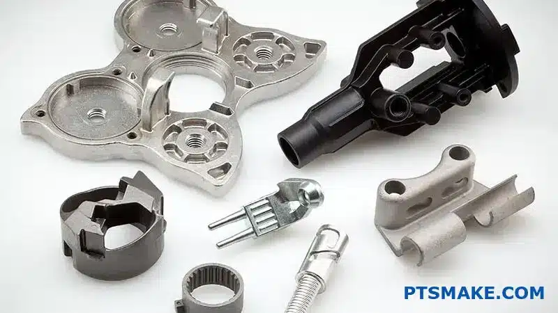
Non-ferrous alloys are the backbone of modern manufacturing. They offer a wide range of properties without the weight and corrosion issues of iron. Let’s look at the main families.
Aluminum Alloys
These are known for being lightweight and corrosion-resistant. They are perfect for aerospace and automotive parts where reducing weight is critical.
Copper Alloys
This group includes brasses and bronzes. They are valued for their excellent electrical conductivity and strength. Think electrical components and marine hardware.
Zinc Alloys
Zinc alloys excel in metal casting. They offer great dimensional accuracy and are ideal for creating complex, detailed parts like gears and decorative hardware.
| Alloy Family | Primary Advantage | Typical Industry |
|---|---|---|
| Aluminum | Lightweight | Aerospace |
| Copper | Conductivity | Electronics |
| Zinc | Castability | Automotive |
Choosing the right alloy is more than just picking one property. It involves balancing performance, cost, and manufacturing requirements. At PTSMAKE, we guide clients through this decision daily.
Deeper Dive into Alloy Selection
Aluminum is light, but its strength can’t match some copper alloys. It’s great for housings but maybe not for high-stress gears. Copper offers superior strength and conductivity. However, it is much denser and typically costs more, which impacts the final part price.
Zinc alloys provide fantastic detail in die casting. They allow for thin walls and complex shapes straight from the mold. This often reduces the need for secondary machining. However, their lower creep strength means they are not suitable for high-temperature applications.
You also need to consider how these alloys interact with other materials. This prevents issues like galvanic corrosion3 in the final assembly. The environment where the part will be used plays a huge role.
| Property | Aluminum Alloys | Copper Alloys | Zinc Alloys |
|---|---|---|---|
| Density (g/cm³) | ~2.7 | ~8.9 | ~7.1 |
| Corrosion Resistance | Excellent | Good to Excellent | Good |
| Electrical Conductivity | Good | Excellent | Good |
| Die Casting Fluidity | Good | Fair | Excellent |
We’ve covered the core non-ferrous families: aluminum, copper, and zinc. Each has unique advantages in weight, conductivity, and castability. The ideal choice depends on your specific application needs, balancing performance against manufacturing realities and overall project cost.
What is the landscape of post-casting finishing operations?
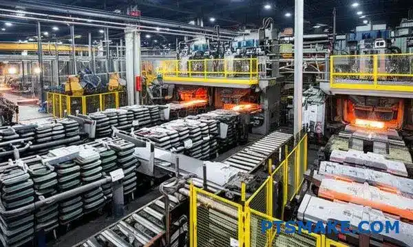
After a part emerges from the mold, its journey is far from over. This is where post-casting finishing begins. It is a critical sequence of operations.
Each step transforms the raw casting into a functional component. This workflow ensures the final product meets exact specifications.
The Standard Post-Casting Workflow
Here is a typical flow we follow. It moves from rough, large-scale removal to fine-tuning and verification.
| Stage | Primary Purpose |
|---|---|
| Shakeout/Knockout | Separating the casting from the mold. |
| Sprue/Riser Removal | Cutting away excess material. |
| Surface Cleaning | Removing scale and sand residues. |
| Heat Treatment | Modifying mechanical properties. |
| Final Inspection | Verifying quality and specifications. |
This structured process is essential for consistent results.
A Deeper Look at Each Stage
Understanding the purpose of each step helps clarify its importance. In my experience, skipping or rushing any stage often leads to quality issues down the line. It’s a chain where every link matters for the final metal casting part.
Initial Separation and Gross Material Removal
The first steps are about brute force. Shakeout violently separates the sand mold from the casting. Afterward, we remove sprues, risers, and gates. These are channels that allowed molten metal to flow.
| Removal Method | Best For | Key Consideration |
|---|---|---|
| Sawing | Large, straight cuts | Fast for bulk removal |
| Grinding | Complex shapes, finishing | More precise but slower |
| Shearing | Brittle materials | Can induce stress |
Refining the Surface and Properties
Once the excess is gone, we focus on refinement. Shot blasting cleans the surface, giving it a uniform finish. This is crucial for subsequent coatings or machining.
Heat treatment then alters the part’s internal microstructure4. This process can increase hardness, improve ductility, or relieve internal stresses created during casting. It is a highly technical but vital step for performance.
Final Quality Assurance
Finally, every part undergoes inspection. This includes dimensional checks with CMMs, visual inspection, and sometimes non-destructive testing (NDT). This is our final promise at PTSMAKE that the part is exactly what the client ordered.
The post-casting workflow is a systematic process. It starts with rough cleaning like shakeout and sprue removal. It then moves to refinement through shot blasting and heat treatment, concluding with a rigorous final inspection to ensure quality.
What are the common heat treatments for metal castings and why?
Heat treatments are not one-size-fits-all. Each process precisely alters a metal casting’s internal structure. This helps us achieve specific properties for the final product.
We mainly rely on three common methods. These are annealing, normalizing, and quenching with tempering.
Key Treatment Goals
Each method serves a distinct purpose. Understanding their goals is key to producing a successful part that performs as expected.
| Treatment | Primary Goal | Result |
|---|---|---|
| Annealing | Stress Relief, Softening | Improved Machinability |
| Normalizing | Grain Refinement | Increased Strength |
| Quenching/Tempering | Hardening | High Hardness & Toughness |
This simple breakdown guides our initial selection process.
Let’s dive deeper into how each process works. The ultimate goal is always to modify the casting’s microstructure. This unlocks the desired mechanical properties for the final application, ensuring reliability and performance.
Annealing: The Stress Reliever
Annealing is like a reset button for the metal. We heat the casting, hold it at a specific temperature, and then cool it very slowly inside the furnace.
This slow cooling allows the internal structure to realign, relieving internal stresses from the casting process. It also makes the metal softer and improves ductility. At PTSMAKE, we often use this to enhance the machinability of complex parts, which reduces tool wear.
Normalizing: Refining the Structure
Normalizing starts like annealing, but the cooling process is different. Instead of cooling slowly in the furnace, the part is cooled in still air.
This faster cooling rate creates a finer, more uniform grain structure. The resulting metal casting is stronger and slightly harder than an annealed one. It provides an excellent balance of strength and toughness for many applications.
Quenching and Tempering: The Ultimate Power-Up
For maximum hardness and strength, we use quenching. The casting is heated until its structure transforms into austenite5. It’s then rapidly cooled in a liquid like water or oil. This process creates a very hard but brittle material.
To reduce this brittleness, we perform a second step: tempering. We reheat the part to a lower, precise temperature. This step increases its toughness.
| Tempering Temperature | Hardness | Toughness |
|---|---|---|
| Low | Very High | Low |
| Medium | High | Medium |
| High | Medium | High |
This two-step treatment delivers superior performance for high-stress parts.
These treatments are essential manufacturing tools. Annealing softens the metal for easier machining. Normalizing provides balanced strength. Quenching and tempering create the ultimate combination of high hardness and toughness for demanding metal casting applications.
How do you design a part for manufacturability (DFM) in metal casting?
To streamline DFM for metal casting, I always rely on a practical checklist. It turns complex theory into simple, actionable steps. This isn’t just about avoiding errors.
It’s about creating an efficient path from design to production. The checklist focuses on four critical areas. These are radii, draft angles, wall thickness, and the parting line.
Key DFM Checklist Items
Here is a simple breakdown of the core principles for any metal casting design. Paying attention to these early on saves significant time and cost later.
| Design Element | Primary Goal |
|---|---|
| Generous Radii | Prevent stress concentrations |
| Draft Angles | Allow easy part removal from mold |
| Uniform Wall Thickness | Ensure even cooling, avoid defects |
| Parting Line | Simplify tooling, improve finish |
A checklist keeps your design grounded in manufacturing reality. Each point addresses a common failure mode in metal casting. Let’s explore why these elements are so vital.
Radii and Stress Points
Sharp internal corners are a major problem. They create areas of high stress concentrations6, which can lead to cracks during cooling or under load. By adding generous radii, you distribute this stress over a larger area, strengthening the part significantly.
Draft Angles for Easy Ejection
A draft angle is a slight taper applied to vertical faces. Without it, removing the part from the mold is difficult. This can damage both the part and the expensive mold. Even a small angle of 1-2 degrees makes a huge difference.
The Importance of Wall Thickness
Molten metal needs to cool evenly. If one section is much thicker than another, it will cool slower. This creates internal stresses and defects like porosity or hot spots. Maintaining a uniform wall thickness is one of the most effective ways to ensure a solid, reliable casting. At PTSMAKE, we guide our clients to achieve this balance effectively.
A comparison highlights the impact:
| Design Choice | Good DFM Practice | Poor DFM Practice |
|---|---|---|
| Corners | Rounded with large radii | Sharp 90-degree angles |
| Walls | Consistent thickness | Abrupt changes in thickness |
| Vertical Faces | Draft angle of 1-3° | 0° draft (straight walls) |
| Parting Line | Placed on a flat, simple plane | Placed across complex features |
A solid DFM checklist is non-negotiable for success. Focusing on radii, draft angles, uniform walls, and parting line placement addresses the most common and costly issues in metal casting, ensuring a smoother production process.
How do you select the appropriate metal casting process for a new product?
Making the right choice can feel complex. But a structured framework simplifies everything. It’s about asking the right questions in the right order.
We start with the non-negotiables. These are the fixed parameters of your project. They act as the first, most important filter.
Your chosen alloy and the physical size of the part are the primary constraints. They immediately eliminate certain metal casting processes, narrowing your options significantly from the start.
| Non-Negotiable | Impact on Process Selection |
|---|---|
| Alloy Type | Determines required melting point and compatibility. |
| Part Size/Weight | Rules out processes with size limitations. |
Once you’ve filtered by the non-negotiables, the next step involves balancing key trade-offs. This is where your business goals come into play.
The Tooling vs. Part Cost Equation
Your expected production volume is the most critical factor here. It directly influences your cost strategy. Are you making 100 parts or 100,000?
For low volumes, a process with low tooling cost like sand casting is often best. The per-part cost might be higher, but the initial investment is minimal.
For high-volume production, investing in more expensive tooling for die casting or investment casting pays off. This drastically lowers the cost per part over the long run. The design of the Gating System7 becomes critical here for consistency.
Matching Requirements to Capabilities
Finally, you must align your design’s technical needs with what each process can deliver.
Surface Finish and Tolerances
Does your part require a smooth, ready-to-use surface? Or will it undergo post-machining? Investment casting provides an excellent finish, while sand casting is much rougher.
Similarly, consider your tolerance requirements. Die casting can hold very tight tolerances, which is essential for complex assemblies. In our projects at PTSMAKE, we use a simple matrix to help clients visualize these final trade-offs.
| Process | Tooling Cost | Unit Part Cost | Typical Tolerances |
|---|---|---|---|
| Sand Casting | Low | High | Loose |
| Investment Casting | High | Medium | Tight |
| Die Casting | Very High | Low | Very Tight |
A solid decision framework begins with non-negotiables like alloy and size. Next, you must balance tooling costs against unit costs based on your production volume. Finally, you match the process capabilities to your specific tolerance and surface finish requirements.
How do you prepare a basic cost estimation for a metal casting?
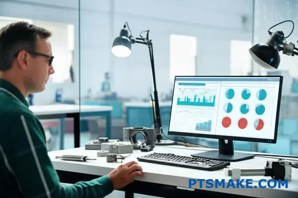
Turning technical knowledge into business sense is crucial. The best way to do this is with a detailed cost model. I always recommend using a simple spreadsheet.
This approach breaks down every expense. It ensures nothing is overlooked.
Key Cost Categories
Your model should include several core components. These form the foundation of your estimate.
| Cost Category | Description |
|---|---|
| Raw Materials | Metal, alloys, sand, binders. |
| Energy | Cost to melt the metal. |
| Labor | Molding, pouring, finishing tasks. |
| Tooling | Pattern and core box costs. |
| Overhead | Factory and administrative expenses. |
This structure makes your metal casting cost estimation clear and manageable.
Turning Technical Data into Financial Insight
A good spreadsheet does more than list costs. It helps you understand their impact. Each line item connects a technical requirement to a specific dollar value.
For example, a more complex design increases labor costs. A specific alloy choice directly affects raw material expenses. This clarity is vital for decision-making.
In past projects at PTSMAKE, we’ve seen how tooling costs can be misleading if not handled properly. Spreading this cost over the expected production volume, a process known as amortization8, gives a more accurate per-part cost.
Detailed Cost Breakdown Example
| Factor | Calculation Basis | Impact on Cost |
|---|---|---|
| Material Cost | Weight per part x Price per kg | Direct & Variable |
| Labor Cost | Hours per part x Hourly rate | Direct & Variable |
| Tooling Amortization | Total tool cost / Total parts | Fixed per part |
| Overhead | % of labor or machine time | Indirect & Fixed |
This detailed view helps you identify the main cost drivers. You can then focus your optimization efforts where they matter most. An accurate model prevents surprises later on.
A structured cost spreadsheet is indispensable. It transforms complex technical details into a clear financial map, empowering you to make informed, strategic decisions for your metal casting projects and ensuring better budget control.
How do you implement a fix for a common metal casting defect?
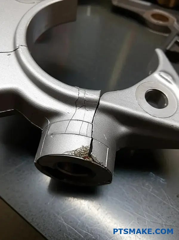
Let’s tackle a common headache in metal casting: shrinkage porosity. Fixing it requires a structured approach, not guesswork. It’s about finding the root cause methodically.
We start with a cause-and-effect diagram. This tool helps us brainstorm and visualize all potential sources of the defect. It provides a clear path to a solution.
For shrinkage, causes often trace back to how the molten metal feeds the mold. An undersized riser or a high pouring temperature are frequent culprits.
| Potential Cause | Category |
|---|---|
| Inadequate Riser | Design |
| High Pour Temp | Process |
| Poor Venting | Mold |
Based on this, we can propose a clear action. For instance, increasing the riser height by 15% to improve the feeding of the casting.
Let’s dive deeper into this structured fix. The fishbone diagram is our primary tool. It breaks the problem into manageable parts: Man, Machine, Material, and Method. This systematic review prevents us from missing a critical factor.
In past projects at PTSMAKE, we’ve found that documenting every variable is crucial. For shrinkage porosity, the ‘Method’ and ‘Material’ categories are often where issues hide. For example, a high pouring temperature can create thermal gradients that lead to voids.
This is where understanding Volumetric shrinkage9 is essential. As metal transitions from liquid to solid, its volume decreases. The riser must act as a reservoir, feeding molten metal to the casting to compensate for this reduction.
If the riser solidifies before the main part, it cannot do its job. This is what creates the defect. After analysis, we might determine a 15% increase in riser height will provide enough material to solve this.
But how do we know the fix worked? We produce a new test batch. Then we verify using non-destructive methods like X-ray inspection.
| Verification Method | Purpose |
|---|---|
| X-Ray Inspection | Detect internal voids non-destructively. |
| Sectioning & Polishing | Visually confirm the absence of porosity. |
| Density Measurement | Compare part density against the material standard. |
This data-driven process provides clear confirmation. It validates our solution and refines our standards for future metal casting work.
To fix shrinkage porosity, we use a fishbone diagram to identify root causes like an undersized riser. We implement a specific solution, like increasing riser height, and then verify its effectiveness with methods such as X-ray inspection and sectioning.
How do you optimize a metal casting process to reduce costs?
Maximizing yield is a direct way to cut costs. Think of it as a simple ratio. We compare the final part’s weight to the total metal poured.
Every bit of metal that isn’t in the final product is a cost. This includes the gating and risering systems needed for the process.
Our goal is to make these systems smaller. But we must do so without sacrificing quality. Reducing the scrap rate is also crucial for improving your bottom line.
A higher yield means less wasted material and more efficient production.
| Metric | Before Optimization | After Optimization |
|---|---|---|
| Total Metal Poured | 15 kg | 13 kg |
| Final Casting Weight | 10 kg | 10 kg |
| Yield Percentage | 66.7% | 76.9% |
Improving yield in metal casting requires a detailed approach. It goes beyond just pouring less metal. It’s about engineering the entire system for efficiency.
The Balancing Act of Gating and Risering
The gating and risering system is essential. It guides molten metal into the mold cavity and feeds the casting as it cools. This prevents defects caused by volumetric shrinkage10.
However, this system is removed after casting and becomes scrap. It needs to be remelted, which consumes energy and time.
The key is optimization. A system that is too large wastes significant material. A system that is too small can lead to defects like porosity, which increases the scrap rate.
At PTSMAKE, we use simulation software. This helps us design the most efficient gating and risering for each unique part. It minimizes material waste while ensuring a sound casting.
Driving Down the Scrap Rate
Scrap parts are a total loss of material, energy, and labor. Identifying the root causes of scrap is the first step to reducing it. Consistent process control is vital.
| Scrap Rate | Cost Impact per 1000 Units |
|---|---|
| 5% | Baseline Cost |
| 3% | Significant Savings |
| 1% | Optimal Efficiency |
Based on our tests, even a small reduction in scrap can lead to substantial cost savings over a production run.
Maximizing your casting yield is a two-part strategy. First, intelligently design gating and risering to reduce material waste. Second, tighten process controls to slash the scrap rate. This directly lowers costs and boosts overall efficiency in any metal casting operation.
Given a failed metal casting, how do you conduct a failure analysis?
A failed metal casting can stop a project cold. To fix it, you need more than a guess. You need a formal procedure.
A systematic approach ensures you find the real root cause. This avoids repeating the same costly mistakes.
The Five-Step Process
Here is a simple breakdown of the process we follow at PTSMAKE. It moves from initial observation to a final, effective solution.
| Step | Action |
|---|---|
| 1 | Document Failure |
| 2 | Gather Data |
| 3 | Analyze Defect |
| 4 | Form Hypothesis |
| 5 | Implement Correction |
This structured method is key to solving complex casting issues.
Why a Formal Procedure is Crucial
Without a formal procedure, teams often jump to conclusions. A structured analysis prevents this by forcing a data-driven approach. It’s about building a case, not just spotting a crack.
Step 1 & 2: Building the Foundation
First, document everything. Take clear photos and note the failure’s location. Then, gather all production data. This includes melt logs, sand test results, and machine parameters. This data provides the context needed for a true analysis. In our past projects, this data has often revealed hidden process variations.
Step 3, 4 & 5: From Analysis to Action
Next, analyze the defect itself. This might involve visual inspection, sectioning the part, or a deeper metallurgical analysis11. Based on all the evidence, you form a logical hypothesis about the root cause. This isn’t a guess; it’s an educated conclusion. Finally, you propose and implement a corrective action plan to prevent recurrence.
Comparing the approaches makes the benefit clear.
| Guesswork Approach | Systematic Procedure |
|---|---|
| Jumps to conclusions | Gathers all available data first |
| Relies on opinion | Based on evidence and analysis |
| Fixes symptoms | Solves the root cause |
| Often leads to repeat failures | Prevents future issues |
A formal process turns a problem into a learning opportunity, strengthening your overall quality control.
A formal, step-by-step procedure is non-negotiable for effective failure analysis. It systematically moves your team from guessing the problem to implementing a validated solution, ensuring the long-term reliability of your metal casting components.
How do you adapt a process for a new, unfamiliar alloy?
Adapting a process for a new alloy isn’t guesswork. It requires a structured research and development plan. This plan acts as your roadmap to success.
Start with the Datasheet
First, get the alloy’s technical datasheet. This document is your primary source of information. It tells you the fundamental properties of the material.
Key Datasheet Parameters
This initial data is critical. It prevents major errors before you even start the metal casting process.
| Parameter | Importance |
|---|---|
| Melting Point | Sets the base for heating temperature. |
| Fluidity | Influences mold filling and detail capture. |
| Shrinkage | Dictates riser and gate design. |
This data provides a strong starting point.
From Theory to Practice
The datasheet provides a theoretical baseline. But real-world manufacturing always has variables. That’s why we move to small-scale testing. It bridges the gap between paper and production.
Running Small-Scale Test Pours
At PTSMAKE, we always run test pours. This step is non-negotiable for unfamiliar materials. We create small, simple molds to observe the alloy’s behavior. This minimizes risk and material waste.
These tests help us fine-tune critical process variables. We analyze how the alloy flows and solidifies. This reveals its true characteristics under our specific conditions. We pay close attention to potential defects caused by issues like poor flow or excessive dendritic shrinkage12.
Fine-Tuning Key Variables
We methodically adjust one variable at a time. This helps isolate its effect on the final part quality. It’s a systematic approach to problem-solving in manufacturing.
| Variable | Adjustment Goal |
|---|---|
| Pouring Temperature | Optimize fluidity without causing gas porosity. |
| Gating System | Ensure complete mold fill without turbulence. |
| Risering | Compensate for shrinkage to prevent voids. |
Based on our test results, we can confidently scale up. This R&D phase ensures our first production run is successful. It’s a foundational step in any reliable metal casting operation.
A solid R&D plan is essential. Start with the alloy’s datasheet for theoretical knowledge. Then, use small-scale test pours to refine your process variables. This structured approach minimizes risks and ensures production readiness.
How do you scale a successful prototype casting to mass production?
Scaling a successful prototype is not just about increasing quantity. It requires a complete strategic shift. The methods that worked for one or ten parts will fail for ten thousand.
From Prototype to Production Tooling
Prototype tooling is often made from softer, faster-to-machine materials. This is great for initial tests. But it won’t last for mass production runs. Durable production patterns are essential for high-volume manufacturing.
| Tooling Type | Lifespan (Cycles) | Material | Best For |
|---|---|---|---|
| Prototype | 10 – 1,000 | Soft Steel, Aluminum | Validation, Low Volume |
| Production | 100,000+ | Hardened Steel | Mass Production |
Embracing Automation
Manual processes introduce variation. To scale effectively, you must automate repetitive tasks like sand mixing, molding, and pouring. Automation ensures consistency and speed.
The Core Challenges of Scaling
Transitioning a prototype to mass production presents several key hurdles. It’s a move from a flexible, hands-on process to a rigid, controlled system. Ignoring these challenges can lead to quality issues and budget overruns.
Upgrading Your Tooling
Temporary prototype tooling cannot withstand the pressures of continuous production. We often guide clients through this transition. We help them invest in hardened steel tooling designed for hundreds of thousands of cycles. This upfront cost is crucial for long-term reliability in any metal casting operation.
Implementing Smart Automation
Automation is more than just replacing labor. It is about creating a repeatable process. Automated systems for sand mixing and molding remove human error. This directly improves part-to-part consistency. The goal is to minimize process variability13 to ensure every single part meets specifications.
Establishing Process Controls
You cannot control what you do not measure. Implementing Statistical Process Control (SPC) is non-negotiable for scaling. This involves real-time monitoring of key variables.
| Monitored Parameter | Why It’s Critical |
|---|---|
| Melt Temperature | Affects fluidity and final grain structure. |
| Pouring Speed | Impacts mold filling and potential for defects. |
| Cooling Rate | Determines final mechanical properties. |
| Sand Moisture | Controls mold strength and surface finish. |
By tracking this data, we can predict and prevent defects before they occur. This keeps quality high and scrap rates low.
Scaling from a prototype to mass production requires a strategic shift to durable tooling, process automation, and robust statistical controls. These elements work together to ensure consistent quality, high output, and long-term success for your product.
How do you solve a recurring defect that defies simple fixes?
When a defect keeps coming back, it’s time to stop guessing. Simple one-factor-at-a-time tests often fail. They can’t uncover complex interactions between process variables.
We need a more powerful, structured method. This is where advanced problem-solving comes into play.
Adopting a Systematic Approach
Design of Experiments (DOE) is a statistical method we use. It helps us systematically test multiple factors at once. This approach is far more efficient than trial and error.
Simple Fix vs. DOE
| Method | Approach | Outcome |
|---|---|---|
| Simple Fix | Change one variable | Often misses interactions |
| DOE | Change multiple variables | Identifies key factors |
When you face a stubborn defect in metal casting, simple adjustments are not enough. Pouring temperature alone might not be the root cause. The problem could be a combination of factors.
This is why we turn to Design of Experiments (DOE). It’s a game-changer. DOE allows us to vary multiple process parameters simultaneously. This reveals how they interact with each other.
Identifying Critical Interactions
Imagine you have a recurring porosity issue. The cause could be pouring temperature, sand composition, or inoculation amount. Changing them one by one is slow and might lead nowhere.
With DOE, we can test different combinations in a structured way. This approach allows us to statistically identify the most significant factors. In past projects at PTSMAKE, we often use a structured approach like an orthogonal array14 to design these experiments efficiently.
Example DOE Factors
| Factor | Level 1 (Low) | Level 2 (High) |
|---|---|---|
| Pouring Temp. | 1400°C | 1450°C |
| Sand Binder % | 3% | 5% |
| Inoculation | 0.1% | 0.2% |
This statistical analysis points directly to the root cause. It shows which combination of settings eliminates the defect for good, saving time and resources.
When simple fixes fail, a systematic approach like Design of Experiments is essential. It moves beyond guesswork, using data to uncover complex interactions and provide a reliable, permanent solution to recurring defects.
Unlock Perfect Metal Casting Solutions with PTSMAKE
Ready to take your metal casting project from concept to flawless production? Contact PTSMAKE now for a custom quote! Our expert team empowers you to overcome challenges, optimize costs, and deliver precision results—no matter your industry or design complexity. Send your inquiry today!

Learn more about how to identify and prevent this common casting defect to ensure part quality and reliability. ↩
Learn how the shape of carbon inside the iron dramatically changes its mechanical properties. ↩
Understand how dissimilar metals can cause accelerated corrosion when in electrical contact. ↩
Learn how internal grain structure impacts the performance and durability of your final parts. ↩
Explore this high-temperature phase’s critical role in transforming steel properties. ↩
Learn how stress points can compromise the structural integrity and lifespan of your cast components. ↩
Learn how this channel design affects your part’s final integrity and surface quality. ↩
Learn how spreading tooling costs over a project’s life improves financial accuracy and decision-making. ↩
Click to understand how metal density changes during cooling and impacts casting quality. ↩
Learn how this fundamental property of cooling metals directly influences the design of casting systems and final part integrity. ↩
Discover the scientific techniques used to examine metal properties and uncover the hidden causes of failure. ↩
Learn how crystal structures form and why they are critical for part strength and integrity. ↩
Learn how controlling this factor ensures consistent quality and reduces production waste. ↩
Learn how this statistical tool simplifies complex experiments and helps you find root causes faster. ↩