Struggling with interference fit failures in your critical assemblies? You’re not alone. Every day, engineers face slipped shafts, cracked hubs, and failed joints that could have been prevented with proper interference fit design.
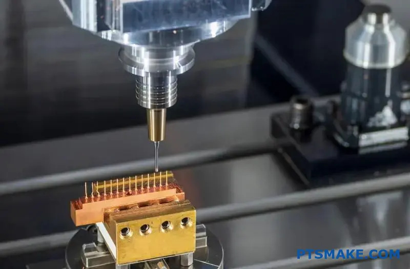
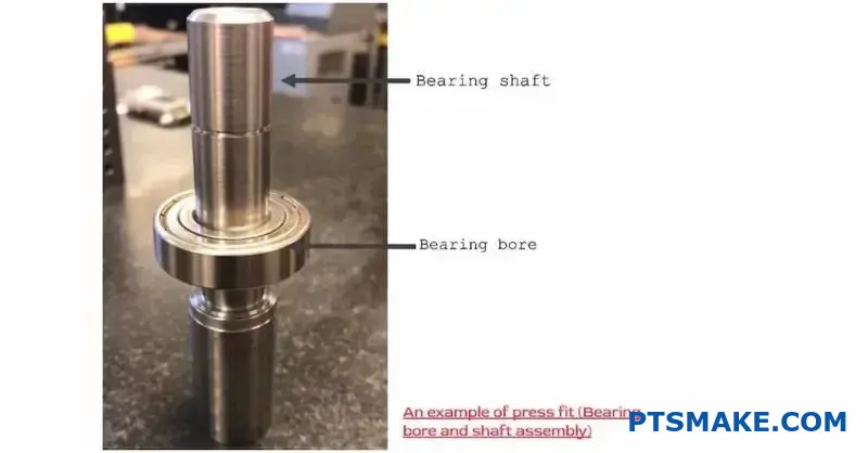
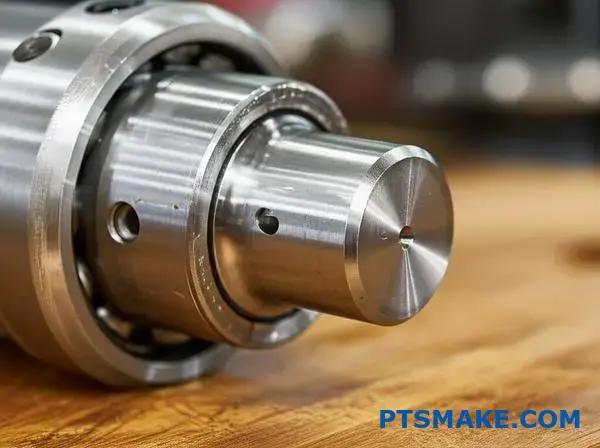
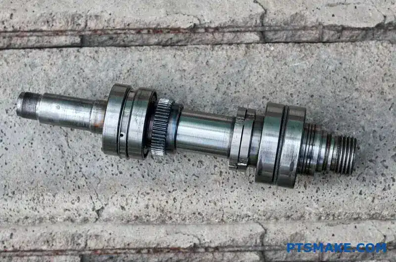
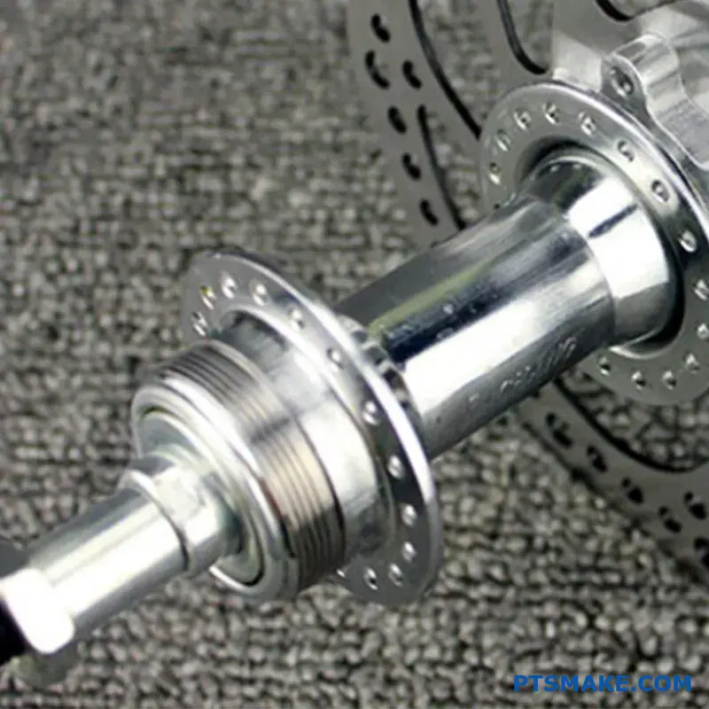
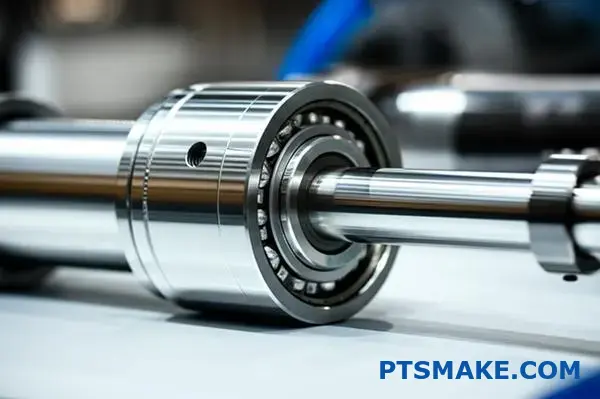
Interference fit is a mechanical fastening method where parts are joined by forcing a slightly oversized component into an undersized mating part, creating radial pressure that generates holding force through friction at the interface.
Getting interference fits right requires understanding the complex relationship between material properties, thermal effects, and stress distribution. The details I’ll share below will help you design reliable interference fits that perform under real operating conditions.
How does effective interference differ from nominal interference?
When designing an interference fit, what’s on your screen isn’t what you get. We call the design value "nominal interference." It’s the pure, calculated difference in dimensions.
However, the "effective interference" is what truly matters. This is the actual interference after assembly.
The Theory vs. Reality Gap
The key difference comes from surface roughness. No surface is perfectly smooth. It has microscopic peaks and valleys.
Understanding the Terms
When parts are pressed together, these tiny peaks compress. This reduces the overall interference. The amount of reduction depends on the material and surface finish.
| Interference Type | Definition | Basis |
|---|---|---|
| Nominal | The theoretical value from drawings. | Ideal, smooth surfaces. |
| Effective | The actual value after assembly. | Real-world, rough surfaces. |
This is a critical first step from theory to practice.
Diving Deeper into Surface Texture
Think of two surfaces under a microscope. They look like mountain ranges. When you press them together, the tips of these mountains, or asperities1, are the first points of contact.
These peaks bear the initial load and deform. They either flatten or break off. This "loss" in height directly subtracts from your nominal interference.
The Role of Surface Finish
A rougher surface has taller peaks. This means more material will be compressed during assembly. Consequently, you lose more of your intended interference.
In our work at PTSMAKE, we see this constantly. A finely ground shaft and a honed bore will have a much higher effective interference than two roughly turned parts, even with the same nominal dimensions. The final Interference fit pressure is directly tied to this effective value.
Quantifying the Loss
Based on our past project data, the loss can be significant. Here’s a general idea:
| Surface Finish | Typical Interference Loss |
|---|---|
| Rough Turned | Can be over 50% of peak height. |
| Ground | Typically 20-30% of peak height. |
| Honed/Lapped | Can be less than 10% of peak height. |
Controlling surface finish is not just for looks; it’s essential for achieving the correct press fit strength and performance.
Nominal interference is the designer’s ideal calculation. Effective interference is the practical reality after surface peaks are compressed during assembly. This crucial difference, governed by surface roughness, determines the final fit’s strength and reliability.
Which material properties most influence the pressure calculation?
When calculating interference fit pressure, two material properties stand out. These are Young’s Modulus and Poisson’s Ratio. They are the primary inputs for any accurate calculation.
Understanding them is crucial for success. Young’s Modulus measures stiffness. Poisson’s Ratio describes how a material deforms. Both directly impact the final pressure.
| Property | Primary Role |
|---|---|
| Young’s Modulus | Measures material stiffness |
| Poisson’s Ratio | Describes deformation shape |
Getting these right ensures your parts fit perfectly. It prevents component failure.
The Role of Young’s Modulus (E)
Young’s Modulus, or the Modulus of Elasticity, is simple. It defines how much a material will stretch or compress under stress. Think of it as a measure of stiffness. A higher modulus means a stiffer material.
For interference fits, this is critical. A stiff material like steel (high E) will generate much higher pressure than a flexible one like aluminum (lower E) for the same interference amount.
In past projects at PTSMAKE, we’ve seen this directly. Mismatched moduli between a shaft and a hub can lead to unexpected stress concentrations. This is something we always account for in the design phase.
Understanding Poisson’s Ratio (ν)
Poisson’s Ratio is a bit less intuitive. When you compress an object, it tends to bulge out to the sides. This ratio quantifies that effect. It is the ratio of transverse strain to axial strain.
This matters because as a shaft is pressed into a hub, both parts deform not just radially but also slightly along their length. This secondary deformation affects the contact area and the overall pressure distribution. Ignoring it can lead to inaccurate pressure calculations, especially with materials that deform significantly. The material is subjected to biaxial stress2 which makes this property important.
| Property Value | Implication for Pressure |
|---|---|
| High Young’s Modulus | Higher pressure for the same fit |
| Low Young’s Modulus | Lower pressure for the same fit |
| High Poisson’s Ratio | More lateral bulging, affects stress |
Young’s Modulus dictates the material’s stiffness, while Poisson’s Ratio describes its deformation behavior. Both are essential for accurately calculating interference fit pressure and ensuring the structural integrity of an assembly. Proper material selection is key.
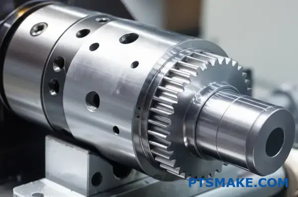
How does a hollow shaft change the pressure calculation?
When you switch from a solid to a hollow shaft, you’re not just removing material. You are fundamentally changing how the part behaves under load. This is a critical detail in design.
The stress distribution becomes more complex. It’s no longer a simple gradient from the center outwards.
Solid vs. Hollow Shaft Basics
A key benefit of a hollow shaft is its higher strength-to-weight ratio. The material at the core of a solid shaft contributes little to its overall stiffness but adds significant weight.
Here is a quick comparison:
| Feature | Solid Shaft | Hollow Shaft |
|---|---|---|
| Weight | Heavier | Lighter |
| Material Cost | Higher | Lower |
| Stiffness/Weight | Lower | Higher |
| Stress Calc. | Simpler | More Complex |
Removing the core changes how forces are managed internally. This directly impacts the interference fit pressure calculations.
Understanding the "why" is key for any engineer. It’s not just about using a different formula. It’s about recognizing the shift in mechanical principles. A hollow shaft behaves more like a thick-walled cylinder, which changes everything.
The Inner Diameter’s Critical Role
The inner diameter introduces a new surface, a new boundary condition. For a solid shaft, the center is a point of zero stress. But in a hollow shaft, the inner wall can now bear stress.
This change introduces significant hoop stress3 at the inner surface, which a solid shaft doesn’t have. This circumferential stress is a direct result of the pressure from the interference fit.
Therefore, the governing equations must account for this new variable. We see this in past projects at PTSMAKE. When we help clients optimize designs, switching to a hollow shaft requires a complete recalculation to ensure the assembly’s integrity. The inner diameter dictates how much the shaft deforms.
Variables in Pressure Equations
Let’s look at the variables needed for each type.
| Shaft Type | Key Geometric Variables |
|---|---|
| Solid Shaft | Outer Diameter |
| Hollow Shaft | Outer Diameter, Inner Diameter |
As you can see, the addition of the inner diameter makes the calculation for a hollow shaft inherently more detailed. Ignoring it leads to inaccurate predictions of assembly strength and potential failure. It changes the stiffness and pressure distribution entirely.
Hollow shafts alter stress distribution and stiffness by introducing an inner diameter. This new variable is essential for accurate interference fit pressure calculations, as it creates a new stress-bearing surface and changes the part’s overall mechanical behavior.
Material Yield Strength: The Ultimate Boundary
The most critical limit is the material’s yield strength. This is the absolute maximum boundary for interference.
Pushing past this point is a line you can’t uncross. The component will permanently deform. It won’t return to its original shape.
This deformation is caused by stress. It builds up from the Interference fit pressure. When the stress exceeds the material’s limit, the part fails.
Understanding this difference is key.
| State | Description | Outcome |
|---|---|---|
| Elastic | Material stretches but returns | No permanent change |
| Plastic | Material permanently deforms | Part is compromised |
Hoop Stress and Plastic Deformation
When you press a shaft into a hub, you create stress. The most significant is hoop stress. Think of it as pressure pushing outwards on the hub. It’s like the tension in a barrel hoop.
As interference increases, this internal stress climbs. The hub material is stretched. This creates a state of biaxial stress4 within the hub material.
At a certain point, the stress reaches the material’s yield strength. This is the elastic limit. Go beyond it, and you cause plastic deformation. The material’s internal structure permanently changes.
The component is now damaged. The designed clamping force is lost. The joint’s integrity is compromised, often leading to premature failure.
In our work at PTSMAKE, selecting the right material is the first step to prevent this. We always analyze the yield strength against the required interference.
Here’s a look at some common materials.
| Material | Typical Yield Strength (MPa) |
|---|---|
| Aluminum 6061-T6 | 276 |
| Mild Steel | 250 |
| Stainless Steel 304 | 215 |
| Titanium (Ti-6Al-4V) | 830 |
This data helps us define a safe maximum interference for any design.
The maximum allowable interference is tied to the material’s yield strength. Exceeding this limit induces stresses that cause permanent plastic deformation. This compromises the component’s integrity and function, leading to assembly failure.
How do various assembly methods affect the final stress state?
Choosing the right interference fit method is crucial. The technique used directly shapes the final stress state of your assembly. We will explore three primary methods.
These are press-fitting, shrink-fitting, and expansion-fitting. Each uses a different principle to achieve the fit. This choice affects everything from component integrity to performance. It is important to understand the trade-offs involved.
Here is a quick overview:
| Method | Principle | Primary Force |
|---|---|---|
| Press-Fitting | Mechanical Force | Compressive |
| Shrink-Fitting | Thermal Contraction (Hub) | Thermal |
| Expansion-Fitting | Thermal Expansion (Shaft) | Thermal |
This comparison sets the stage for a deeper look.
A Closer Look at Assembly Techniques
Each assembly method introduces stress in a unique way. The final state depends entirely on the process you choose. Let’s break down the specifics.
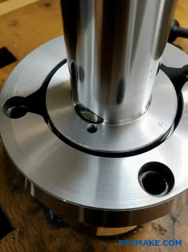
Press-Fitting: The Brute Force Method
Press-fitting uses mechanical force to push two parts together. It’s direct but can be harsh on components. This method carries a high risk of scoring and galling as the surfaces slide under immense pressure.
The process creates significant localized stress at the point of entry. It can also cause some elastic-plastic deformation5, which might compromise the surface integrity and the final holding force.
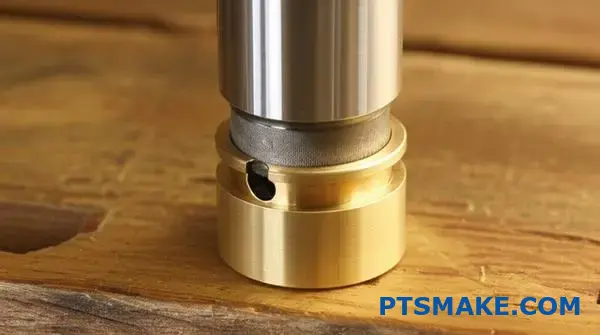
Thermal Methods: A Gentler Approach
Shrink-fitting and expansion-fitting use temperature to their advantage. They offer a much cleaner assembly process with minimal risk of surface damage.
In shrink-fitting, you heat the outer part. For expansion-fitting, you cool the inner part. Both create a more uniform interference fit pressure and stress distribution compared to press-fitting. However, thermal methods can alter material properties if not controlled carefully.
At PTSMAKE, we help clients select the best method. We analyze materials, tolerances, and application stresses to find the right balance for production.
| Method | Scoring/Galling Risk | Residual Stress Profile | Key Challenge |
|---|---|---|---|
| Press-Fitting | High | Localized, high at entry | Surface damage control |
| Shrink-Fitting | Low | Uniform, thermal-induced | Material property changes |
| Expansion-Fitting | Low | Uniform, thermal-induced | Process complexity/cost |
Each method—press, shrink, and expansion fitting—offers a distinct balance of risks and benefits. Press-fitting is mechanical and risks surface damage, while thermal methods provide cleaner fits but introduce different material considerations. The best choice depends on your specific design requirements.
What are the common failure modes in interference fit joints?
Interference fits are robust but not invincible. Understanding their potential failure points is crucial for creating reliable designs. If the fit is not perfect, problems will arise.
The four most common failures are distinct. They range from simple slippage to catastrophic hub bursting. Each mode has a clear root cause, usually related to pressure or movement.
Let’s outline these key failure modes.
| Failure Mode | Primary Cause |
|---|---|
| Slippage | Insufficient Pressure |
| Hub Yielding | Excessive Pressure |
| Fretting Corrosion | Micromovement |
| Fatigue Failure | Stress Concentration |
Knowing these is the first step to prevention.
Let’s explore these failure modes in more detail. Success often hinges on getting the balance right. Too much or too little force is the core issue.
Slippage
Slippage occurs when the clamping force is too low. The shaft starts to rotate or move axially inside the hub under operational loads. The joint can no longer transmit the required torque. This is a direct result of insufficient interference fit pressure.
Hub Yielding and Bursting
This is the opposite scenario. Too much interference creates extreme hoop stress in the hub. This can cause the material to yield and deform permanently. For brittle materials, this can lead to a complete fracture or bursting of the hub during assembly.
Fretting Corrosion
Even in a tight fit, dynamic loads can cause tiny, repetitive movements between the shaft and hub. These micromovements rub the surfaces together, creating wear debris that then oxidizes. This entire process, called fretting corrosion6, creates surface pits that can initiate fatigue cracks.
Fatigue Failure
Cyclic loads can cause cracks to form and grow over time, leading to fatigue failure. These cracks almost always start at points of high stress concentration. The edges of the press-fit joint are classic examples of such high-stress areas.
Here’s a quick look at the conditions leading to failure.
| Failure Mode | Stress Condition | Load Type |
|---|---|---|
| Hub Yielding | High Static Stress | Assembly Load |
| Slippage | Low Clamping Force | Operational Load |
| Fretting/Fatigue | Cyclic Stress | Operational Load |
Recognizing these failure modes is critical for engineers. The key takeaway is the importance of controlling the interference fit pressure. It must be strong enough to prevent slippage but not so high that it causes the hub to yield or fail from fatigue.
How does operating temperature affect an interference fit?
Temperature is a critical factor for interference fits. This is especially true when using dissimilar materials. We call this effect differential thermal expansion.
Different materials expand and contract at different rates. When the temperature changes, this can alter the fit.
A tight fit can become loose. Or, it can become dangerously tight. This change directly impacts the interference fit pressure, risking assembly failure. Understanding this is key for reliable design.
Understanding the Coefficient of Thermal Expansion (CTE)
Every material has a unique coefficient of thermal expansion7 (CTE). This value tells us how much a material will expand or shrink for each degree of temperature change. It’s a fundamental property we must consider in our designs.
When you assemble parts made from different materials, their different CTEs can cause problems. An aluminum hub on a steel shaft is a classic example. Their reactions to heat are not the same.
How Temperature Changes Affect the Fit
The interaction between materials dictates the assembly’s stability. Both heating and cooling present unique challenges to the interference fit pressure. At PTSMAKE, we always model these effects for critical applications.
When Temperature Rises
If the outer part (hub) has a higher CTE than the inner part (shaft), it will expand more when heated. This reduces the interference, potentially causing the joint to loosen or slip.
Conversely, if the shaft has a higher CTE, it will expand more. This increases the interference and stress, which can lead to component failure.
Here is a quick look at the CTE for some common materials.
| Material | Coefficient of Thermal Expansion (10⁻⁶ /°C) |
|---|---|
| Aluminum | 23.1 |
| Brass | 19.0 |
| Steel (Carbon) | 12.0 |
| Stainless Steel | 17.3 |
| Titanium | 8.6 |
When Temperature Drops
The opposite happens in cold environments. If the hub has a higher CTE, it will shrink more than the shaft. This tightens the fit, increasing the stress on both components. This can lead to cracking or permanent deformation.
Differential thermal expansion is a crucial design consideration. Mismatched material expansion rates can significantly alter interference fit pressure. This can lead to either joint loosening or excessive stress, both of which risk component failure.
How do dynamic loads differ from static loads on a fit?
Dynamic loads introduce unique challenges not seen with static forces. Constant changes in direction or magnitude can cause tiny movements at the fit interface.
The Danger of Micromovements
These micromovements might seem small. But over millions of cycles, they can lead to a specific type of failure. This is a critical concern for moving parts.
Impact of Rotational Speed
In rotating machinery, speed adds another layer of complexity. High speeds generate significant forces that can compromise the integrity of a press fit. This directly affects the interference fit pressure.
| Load Type | Primary Effect on Fit | Key Challenge |
|---|---|---|
| Dynamic | Micromovements, Vibration | Fretting Fatigue |
| Rotational | Centrifugal Force | Reduced Fit Pressure |
Dynamic loads, especially cyclic or reversing ones, are a primary cause of micromovements between fitted surfaces. Even in a seemingly solid press fit, these loads create minute slipping actions. This repetitive rubbing under pressure can initiate surface cracks.
Over time, these tiny cracks propagate, leading to a failure mode known as fretting fatigue8. This is particularly dangerous because it can cause a component to fail well below its expected material fatigue limit. We see this often in components for aerospace and automotive applications.
Centrifugal Forces at High Speeds
For rotating assemblies, speed is a major factor. As a part spins faster, centrifugal force tries to pull it outwards. This force acts against the clamping pressure of an interference fit.
This effect can significantly reduce the effective interference fit pressure. At very high speeds, it can even cause the fit to loosen completely. In our work at PTSMAKE, we account for this when designing high-speed motor shafts and hubs.
Rotational Speed vs. Fit Pressure
| Rotational Speed | Centrifugal Force | Effect on Interference Fit Pressure |
|---|---|---|
| Low | Negligible | Minimal reduction |
| Medium | Moderate | Noticeable reduction |
| High | Significant | Critical reduction; potential loosening |
This is why a fit designed for a static load might fail prematurely in a dynamic, high-speed application. Careful analysis is essential.
Dynamic conditions introduce fretting fatigue from micromovements and reduce fit integrity through centrifugal forces. These factors are critical for the design of reliable, long-lasting assemblies and must be carefully considered beyond static load calculations.
How does surface finish and lubrication impact the fit?
Lubricants play a crucial role in mechanical assemblies. They are especially vital for interference fits. They significantly ease the assembly process.
The Double-Edged Sword of Lubrication
However, this benefit comes with a trade-off. While lubricants reduce friction for easier assembly, this can also weaken the final joint’s holding power.
Key Effects of Lubricants
Choosing the right lubricant is a balancing act. You must weigh the assembly advantages against potential performance reductions in your design.
| Aspect | Positive Impact | Negative Impact |
|---|---|---|
| Assembly Force | Significantly reduced | – |
| Galling Risk | Minimized | – |
| Joint Strength | – | Can be compromised |
| Torque Capacity | – | Potentially lowered |
This table shows the clear trade-offs involved.
Easing Assembly, Reducing Risks
In press-fit and shrink-fit operations, lubricants are key. They greatly lower the force required to mate components. This minimizes the risk of damage during assembly.
One of the most important benefits is preventing galling. Galling occurs when two surfaces seize and weld together under extreme pressure. Lubricants form a barrier film, stopping this.
The Hidden Cost: Reduced Holding Power
But here is the downside. The primary function of a lubricant is to reduce the static coefficient of friction. This is the exact force that gives an interference fit its strength.
This reduction directly affects the joint’s holding capacity. The effective interference fit pressure is lower. This can diminish the joint’s ability to transmit torque or withstand axial forces. The study of these surface interactions is a core part of tribology9.
Comparing Lubricated vs. Dry Fits
In our work at PTSMAKE, we manage this balance carefully. The choice of lubricant is not a minor detail. It is a critical design decision.
| Fit Condition | Assembly Force | Galling Risk | Static Friction | Torque Capacity |
|---|---|---|---|---|
| Dry Fit | High | High | High | Maximum |
| Lubricated Fit | Low | Low | Low | Reduced |
This comparison highlights the fundamental compromise. You achieve an easier, safer assembly at the expense of some final holding strength. Proper engineering must account for this.
Lubricants are a crucial but complex factor. They simplify assembly and prevent surface damage like galling. However, they also reduce the static friction needed for a strong interference fit, which can compromise the joint’s final torque transmission capability.
How do you calculate the required interference for a given torque?
Calculating the required interference is a precise engineering task. Let’s walk through the five essential steps. This process ensures your press-fit assembly can handle the specified load without slipping. It all starts with defining your operational needs.
Step 1: Determine Required Torque
First, identify the torque your assembly must transmit. Then, apply a safety factor. This accounts for unexpected loads or material variations.
| Application Type | Recommended Safety Factor |
|---|---|
| Smooth, steady loads | 1.2 – 1.5 |
| Light shock loads | 1.5 – 2.0 |
| Heavy shock loads | 2.0 – 3.0 |
Step 2: Calculate Tangential Force
With the design torque known, you can find the required tangential force at the interface.
Step 3: Use Friction to Find Normal Force
The coefficient of friction between the shaft and hub materials is critical. It dictates the normal force needed to generate the required tangential (frictional) force. This value prevents rotational slippage under torque.
Selecting an accurate coefficient is vital. This value changes based on material pairings, surface finish, and whether a lubricant is used during assembly.
| Material Combination | Typical Coefficient of Friction (Dry) |
|---|---|
| Steel on Steel | 0.15 – 0.20 |
| Steel on Aluminum | 0.18 – 0.25 |
| Steel on Cast Iron | 0.17 – 0.22 |
Step 4: Calculate Required Interface Pressure
Once you have the normal force, you can calculate the required interference fit pressure. This pressure is distributed over the entire contact area of the interference joint. A higher pressure ensures a stronger grip. This is a key parameter we focus on at PTSMAKE to guarantee component performance.
Step 5: Solve for the Required Interference
Finally, we use Lame’s equations10 to connect the required pressure to the physical interference value. These formulas account for the geometry of the hub and shaft as well as their material properties, like Young’s Modulus and Poisson’s Ratio. In our experience, this final calculation is where precision matters most.
This five-step process methodically translates a torque requirement into a precise dimensional interference. Following these steps ensures a reliable mechanical assembly that performs as designed, preventing costly failures and ensuring operational safety for the final product.
How do you design a robust fit between steel and aluminum?
Designing a fit for dissimilar materials like steel and aluminum is tricky. The main challenge comes from temperature changes. Aluminum expands and contracts about twice as much as steel.
This means a perfect fit at room temperature might fail at high or low temperatures. Your design must work across the entire operational range. We need to check two critical extremes: cold and hot.
Key Temperature Considerations
| Extreme | Primary Risk | Design Goal |
|---|---|---|
| Cold | Parts slipping apart | Maintain sufficient interference fit pressure |
| Hot | Hub cracking or yielding | Stress must not exceed yield strength |
Analyzing the Temperature Extremes
When designing, you must prioritize the hot and cold limits of your application. These extremes present opposite challenges that need careful balancing. In past projects at PTSMAKE, we’ve seen designs fail because they only considered standard operating conditions.
The Cold Condition: Preventing Slip
As temperature drops, the aluminum hub shrinks more than the steel shaft. This reduces the initial interference. The contact pressure, or interference fit pressure, decreases as a result.
If the temperature drops low enough, this pressure may not be enough to handle the torque. The result is slippage, which leads to failure. Your calculation must confirm that enough interference remains at the lowest temperature to transmit the required load. The different coefficient of thermal expansion11 is the key factor here.
The Hot Condition: Avoiding Hub Failure
Conversely, as temperature rises, the aluminum hub expands more than the steel shaft. This dramatically increases the interference and the resulting stresses within the hub.
This high stress, often called hoop stress, can cause the aluminum hub to permanently deform or even crack if it exceeds the material’s yield strength. Based on our tests, you must verify that the maximum stress in the hub at the highest temperature stays safely below its yield point.
Summary of Key Design Checks
| Temperature | Aluminum Hub Behavior | Steel Shaft Behavior | Main Concern |
|---|---|---|---|
| Cold | Shrinks significantly | Shrinks less | Loss of interference, potential slip |
| Hot | Expands significantly | Expands less | High stress, potential yielding/failure |
To create a robust fit, you must analyze both temperature extremes. You need sufficient interference to prevent slip when cold, but not so much that the hub fails from stress when hot. This balance is critical for long-term reliability.
When is an interference fit the wrong engineering solution?
True mastery of any tool means knowing its limits. An interference fit is a powerful engineering solution. But it is not always the right one.
Understanding when to choose an alternative is critical. This ensures your design is reliable, serviceable, and cost-effective in the long run. Let’s explore some common scenarios.
Scenarios to Reconsider
| Scenario | Interference Fit Suitability |
|---|---|
| Frequent Disassembly | Poor |
| Precise Axial Positioning | Moderate |
| Very High Torque | Good, but with limits |
These situations often call for different joining methods. Making the right choice upfront saves time and money.
Knowing the limitations of an interference fit is key. In our work at PTSMAKE, we often guide clients toward the best solution for their specific application. An interference fit creates a strong, semi-permanent joint. This is a disadvantage when regular maintenance is needed.
When Frequent Disassembly is Required
Repeatedly pressing a joint apart can damage components. It causes material fatigue and loss of dimensional accuracy. The calculated interference fit pressure might not be achieved on reassembly.
Better Alternative: Tapered Sleeves or Clamps
Tapered sleeves provide a secure fit that is easily disengaged. Clamps offer an even simpler solution for non-critical applications, allowing for quick adjustments and removal without specialized tools.
When Precise Axial Positioning is Needed
Pressing a shaft into a hub can be unpredictable. The final axial position can vary slightly with each assembly. This lack of precise control is unacceptable for components like gears or bearings that require exact placement.
Better Alternative: Shoulder and Nut
A shoulder on the shaft provides a positive stop. A locknut secures the component against it. This method guarantees exact and repeatable axial positioning, which is critical for many mechanical systems. For very high torque, a simple friction fit may not be enough. Slippage can occur under extreme load, leading to failure. Here, a positive connection is required. An interference fit relies on friction, but a mechanical interlock12 is better for these cases.
| Alternative | Best Use Case |
|---|---|
| Tapered Sleeves | Frequent, precise reassembly |
| Shoulder and Nut | Exact axial positioning |
| Splines / Keyways | Extreme torque transmission |
In summary, while interference fits are excellent for permanent joints, they are unsuitable for parts needing regular disassembly, precise positioning, or extreme torque transfer. Recognizing these limits is key to robust and serviceable design.
Unlock Precision Fits with PTSMAKE Today
Ready to ensure optimal interference fit pressure for your next project? Contact PTSMAKE now for a fast, detailed quote on precision CNC machining and injection molding solutions. Let our expertise in reliable, high-tolerance manufacturing elevate your product’s performance—start your inquiry today!

Get a detailed breakdown of how these microscopic surface peaks influence component performance. ↩
Understand how stress in multiple directions impacts material behavior in assemblies. ↩
Learn how this circumferential stress is calculated in thick-walled cylinders. ↩
Click to learn how multiple stresses impact material failure in press-fit designs. ↩
Understand how materials behave under stress beyond their elastic limit and why it matters for joint strength. ↩
Learn how this subtle wear mechanism can cause major structural failures in dynamically loaded joints. ↩
Discover how this crucial property impacts material selection in high-performance engineering applications. ↩
Learn more about this specific failure mode and how to prevent it in your designs. ↩
Learn more about how friction, wear, and lubrication affect mechanical systems. ↩
Discover the formulas used to calculate stresses in thick-walled cylinders under pressure. ↩
Understand how this value directly impacts your calculations for interference fits across different temperatures. ↩
Explore how different mechanical locking mechanisms compare for high-torque applications. ↩