Sie sind dabei, ein Getriebesystem neu zu konstruieren, und die Stirnräder verursachen einen inakzeptablen Geräuschpegel. Der Zeitplan für Ihr Projekt ist eng, Ihr Budget ist begrenzt und der Wechsel zu schrägverzahnten Zahnrädern bedeutet, dass das gesamte Lagersystem und das Gehäuse neu konstruiert werden müssen.
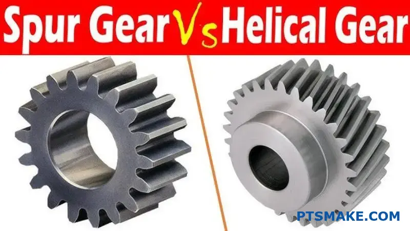
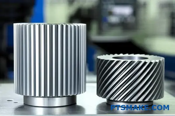
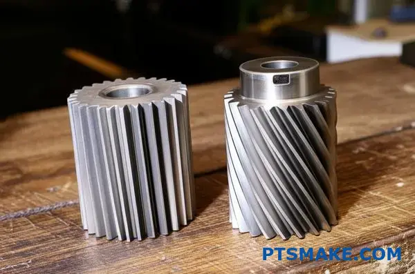
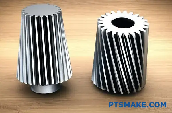
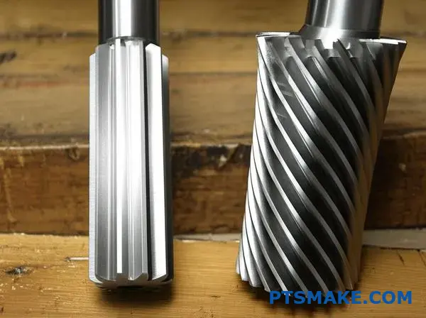
Stirnräder haben gerade Zähne, die parallel zur Wellenachse verlaufen, während Schrägzahnräder gewinkelte Zähne haben, die eine Schraubenlinie um den Zahnradumfang bilden. Dieser grundlegende Unterschied wirkt sich auf alles aus, vom Geräuschpegel und der Tragfähigkeit bis hin zu den Herstellungskosten und Lageranforderungen.
Durch meine Arbeit bei PTSMAKE habe ich Ingenieuren dutzende Male geholfen, genau diese Entscheidung zu treffen. Jeder Getriebetyp hat spezifische Stärken, die ihn für bestimmte Anwendungen ideal machen. Dieser Leitfaden führt Sie durch die technischen Unterschiede, Leistungsabwägungen und Auswahlkriterien, damit Sie die richtige Wahl für Ihr Projekt treffen können.
Was ist die grundlegende Geometrie, die einen Stirnradzahn definiert?
Das Geheimnis der Leistung eines Stirnradgetriebes ist nicht nur seine Form, sondern eine ganz bestimmte Kurve. Diese Kurve ist die Grundlage der Konstruktion.
Das unvollständige Profil
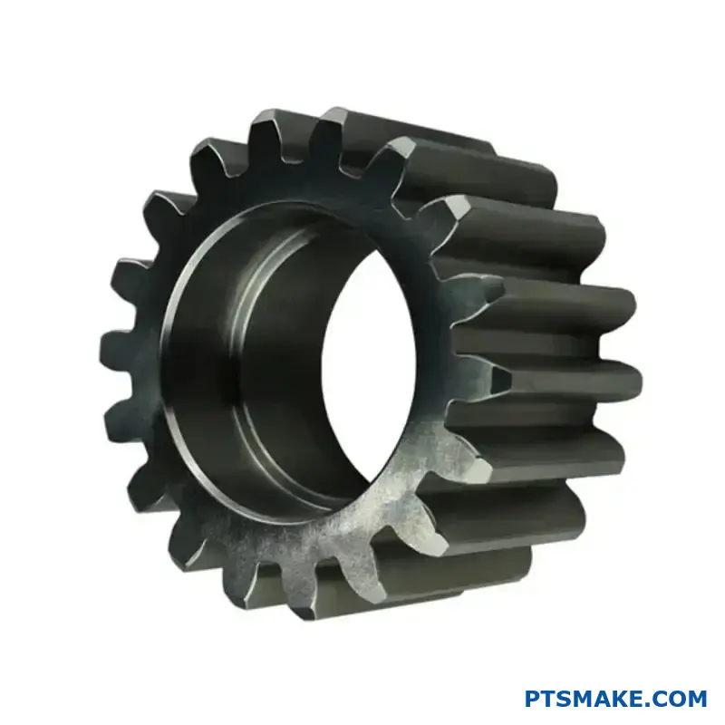
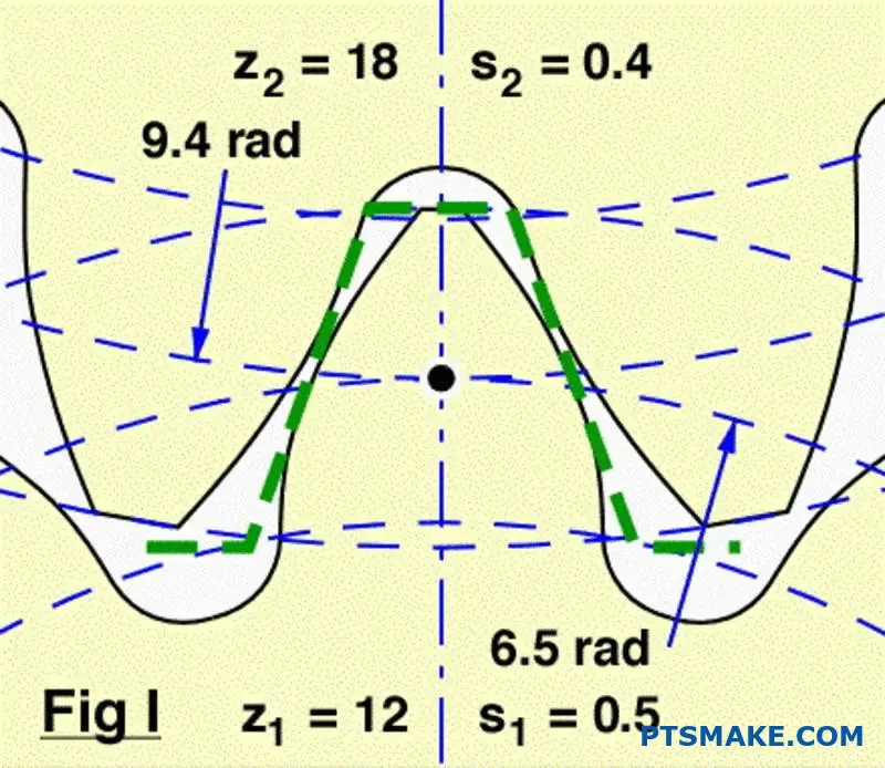
Das Zahnprofil eines modernen Stirnrads ist im Kern eine Evolventenkurve. Stellen Sie sich vor, Sie wickeln eine Schnur von einem Zylinder ab.
Diese spezielle Geometrie ist entscheidend. Sie sorgt dafür, dass beim Ineinandergreifen der Zahnräder die Drehzahl vollkommen konstant bleibt. Das verhindert Ruckeln und ungleichmäßigen Kraftfluss.
| Merkmal Geometrie | Zweck |
|---|---|
| Evolventenkurve | Konstantes Geschwindigkeitsverhältnis |
| Gerader Zahn | Axiale Leistungsübertragung |
| Richtige Abstände | Reibungsloses Engagement |
Wie der Involute einen reibungslosen Betrieb gewährleistet
Die Evolventenform ist nicht willkürlich. Es handelt sich um ein präzises mathematisches Profil, das vor allem aus einem Grund entwickelt wurde: um ein konstantes Geschwindigkeitsverhältnis zwischen den ineinander greifenden Zahnrädern zu gewährleisten. Dies ist ein unverzichtbares Prinzip für eine effiziente Kraftübertragung.
Die Magie des Normalen
Wenn sich zwei Zahnräder berühren, verläuft die gemeinsame Normale (eine Linie senkrecht zu den Oberflächen im Berührungspunkt) immer durch einen festen Punkt. Dieser Festpunkt wird als Wälzpunkt bezeichnet.
Diese gleichmäßige Geometrie sorgt dafür, dass das treibende Zahnrad das angetriebene Zahnrad mit gleichmäßiger Geschwindigkeit schiebt. Während des Eingriffs gibt es keine Beschleunigungen oder Verlangsamungen. Dies ist ein wesentlicher Unterschied beim Vergleich von Stirnradgetriebe im Vergleich zu Schrägstirnrädernda beide für einen reibungslosen Betrieb auf dieses Prinzip angewiesen sind.
Die Evolventenkurve wird aus einer Grundkreis1. Die Größe dieses Kreises ist grundlegend für die endgültige Zahnform und ihre Leistungsmerkmale. Bei unserer Arbeit bei PTSMAKE ist die richtige Geometrie entscheidend für die hochpräzisen Teile, auf die unsere Kunden angewiesen sind.
| Design-Aspekt | Konsequenz der involuten Geometrie |
|---|---|
| Kontaktstelle | Bewegt sich entlang der Zahnoberfläche |
| Aktionsbereich | Bleibt konstant und tangiert beide Grundkreise |
| Geschwindigkeitsverhältnis | Bleibt in der gesamten Masche konstant |
Die Evolventenkurve ist die grundlegende Geometrie für eine Stirnradverzahnung. Dieses spezifische Profil ist für das Erreichen eines konstanten Geschwindigkeitsverhältnisses, das eine reibungslose, zuverlässige und effiziente Kraftübertragung zwischen den ineinander greifenden Zahnrädern gewährleistet, unerlässlich.
Wie verändert ein Schrägungswinkel die Eigenschaften eines Zahnrads grundlegend?
Der Schrägungswinkel ist das wichtigste Einzelmerkmal. Er unterscheidet ein Schrägzahnrad von einem Geradzahnrad. Er ist nicht nur eine optische Verbesserung.
Stirnräder haben gerade Zähne. Sie greifen über ihre gesamte Fläche auf einmal ein. Dadurch entsteht ein abrupter, geradliniger Kontakt.
Schrägverzahnte Räder mit ihren abgewinkelten Zähnen greifen anders ein. Der Kontakt beginnt an einem Ende des Zahns. Er bewegt sich dann sanft über die Fläche, während sich das Zahnrad dreht.
Dieses schrittweise Engagement ist der Schlüssel.
| Merkmal | Stirnrad | Stirnradgetriebe |
|---|---|---|
| Zahnausrichtung | Gerade | Gewinkelt (Helix-Winkel) |
| Erster Kontakt | Vollständige Zeile | Kontaktperson |
| Verlobungsstil | Abrupt | Allmählich und sanft |
Die Mechanik des schrittweisen Engagements
Dieses allmähliche Ineinandergreifen ändert alles. Im Gegensatz zum plötzlichen Aufprall bei Stirnrädern gleiten die Schrägzähne ineinander. Die Last wird schrittweise aufgebracht, nicht auf einmal. Dadurch werden Stöße und Vibrationen erheblich reduziert.
Das Ergebnis ist ein wesentlich leiserer Betrieb. Das ist einer der Hauptgründe, warum Konstrukteure schrägverzahnte Getriebe den Stirnrädern vorziehen. Bei früheren Projekten von PTSMAKE hat der Wechsel zu schrägverzahnten Getrieben die Betriebsgeräusche deutlich reduziert. Dies ist für medizinische Geräte und Unterhaltungselektronik von entscheidender Bedeutung.
Dieser schräge Kontakt hat jedoch einen Nebeneffekt. Er erzeugt Axialschub2eine Kraft, die parallel zur Achse des Zahnrads verläuft. Diese Kraft ist bei Stirnrädern nicht vorhanden und muss bewältigt werden. Die richtige Auswahl der Lager ist entscheidend, um diese Belastung zu bewältigen und einen vorzeitigen Ausfall zu verhindern.
Dieser Kompromiss ist der Kern der Debatte über Stirnradgetriebe im Vergleich zu schrägverzahnten Getrieben.
| Aspekt des Engagements | Vorteil | Nachteil |
|---|---|---|
| Allmählicher Kontakt | Sanfterer, leiserer Betrieb | Erzeugt axiale Schubkraft |
| Gewinkelte Zähne | Höherer Gesamtberührungsgrad | Erfordert robuste Lager |
| Verteilung der Last | Erhöhte Tragfähigkeit | Komplexere Fertigung |
Eine Verschiebung der Lastverteilung
Dieser allmähliche Eingriff bedeutet auch, dass die Last zu jedem Zeitpunkt auf mehrere Zähne verteilt ist. Dies steht im Gegensatz zu Stirnrädern, bei denen ein oder zwei Zähne die gesamte Last tragen. Dank dieser Teilungsfähigkeit können Schrägzahnräder größere Lasten bewältigen und haben eine längere Lebensdauer.
Der Schrägungswinkel verändert den Zahnradkontakt grundlegend von einer abrupten Linie zu einem glatten, progressiven Bereich. Diese Verschiebung ist die Quelle der Vorteile in Bezug auf Geräusch und Tragfähigkeit, bringt aber auch die Herausforderung des Axialschubs mit sich.
Welche Kräfte wirken auf einen einzelnen Stirnradzahn während des Eingriffs?
Um wirklich zu verstehen, was beim Zahneingriff passiert, müssen wir die Gesamtkraft aufschlüsseln. Diese Kraft wirkt nicht geradeaus. Sie wirkt in einem Winkel zur Zahnoberfläche.
Ingenieure vereinfachen dies, indem sie die Kraft in zwei Hauptkomponenten aufteilen. Dies erleichtert die Analyse und Konstruktion erheblich. Dies sind die tangentialen und radialen Kräfte. Beide haben eine sehr unterschiedliche Wirkung auf das Zahnradsystem.
Verstehen der Kraftkomponenten
Im Folgenden werden diese beiden Kräfte und ihre Hauptaufgaben in einem Getriebesystem kurz beschrieben.
| Kraftkomponente | Primäre Funktion | Wichtigste Auswirkungen |
|---|---|---|
| Tangentiale Kraft | Sendet Leistung | Erzeugt ein Drehmoment zum Antrieb der Last |
| Radiale Kraft | Trennt Gänge | Belastung von Lagern und Wellen |
Die "arbeitende" Kraft: Tangentialkomponente
Die tangentiale Kraft ist die Komponente, die die ganze nützliche Arbeit leistet. Sie wirkt tangential zum Teilkreis des Zahnrads. Dies ist die Kraft, die tatsächlich das Drehmoment überträgt und das angetriebene Zahnrad in Drehung versetzt. Wenn Sie mehr Drehmoment benötigen, haben Sie es mit einer größeren Tangentialkraft zu tun.
Die trennende Kraft: Radialkomponente
Die Radialkraft hingegen leistet keine nützliche Arbeit für die Kraftübertragung. Ihre Aufgabe ist es, die beiden Zahnräder entlang einer Verbindungslinie zwischen ihren Mittelpunkten auseinander zu drücken. Diese Trennkraft ist ein kritischer Faktor für die Konstruktion. Sie belastet direkt die Wellen und die Lager, die sie tragen.
Bei früheren Projekten von PTSMAKE haben wir erlebt, dass Konstruktionen scheiterten, weil die Lager nicht für die Aufnahme der Radiallasten ausgelegt waren. Dies ist ein entscheidender Unterschied in der Debatte zwischen Stirnrädern und Schrägstirnrädern, da Schrägstirnräder auch eine Axialkraft (Schubkraft) erzeugen.
Die Größe dieser Kräfte wird durch das Getriebe bestimmt Eingriffswinkel3. Ein größerer Winkel erhöht die Radialkraft im Verhältnis zur Tangentialkraft.
Übersicht über die Kraftrichtung
| Kraft | Richtung der Aktion | Konsequenz |
|---|---|---|
| Tangential | Tangente zum Teilkreis | Drehmomentübertragung |
| Radial | In Richtung Gear Center | Lagerbelastung |
Die Gesamtkraft, die auf einen Stirnradzahn wirkt, lässt sich am besten anhand ihrer tangentialen und radialen Komponenten verstehen. Die tangentiale Kraft treibt die Maschine an, während die radiale Kraft Belastungen auf die Wellen und Lager erzeugt. Bei der richtigen Konstruktion werden beide Komponenten berücksichtigt.
Welche neue Kraftkomponente wird durch die Schrägverzahnung eingeführt?
Schrägverzahnte Zahnräder weisen eine bedeutende Kraftkomponente auf, die es bei Stirnrädern nicht gibt: den Axialschub. Diese Kraft wirkt parallel zur Achse des Zahnrads und drückt das Zahnrad im Wesentlichen seitwärts.
Die Ursache liegt in den schrägen Zähnen des Zahnrads.
Ein entscheidender Designunterschied
Wenn Schrägzähne ineinandergreifen, erzeugt der Kontakt eine Kraft, die nicht senkrecht zur Welle steht. Dadurch entsteht die axiale Komponente.
| Getriebetyp | Primäre Kräfte | Neue Kraftkomponente |
|---|---|---|
| Stirnrad | Radial, Tangential | Keine |
| Stirnradgetriebe | Radial, Tangential | Axialschub |
Diese neue Kraft erfordert ein sorgfältiges Management in Ihrem Entwurf.
Die Physik des Axialschubs
Der Schrägungswinkel ist die direkte Ursache des Axialschubs. Bei der Kraftübertragung wirkt die Kraft auf die Zahnoberfläche senkrecht zum Zahn selbst. Da der Zahn in einem Winkel steht, zerfällt diese Kraft in zwei Hauptkomponenten.
Die eine ist die tangentiale Kraft, die die Rotation antreibt. Die andere ist die Axialkraft, die auf die Welle drückt. Dies ist ein zentrales Konzept beim Vergleich von Stirnrädern mit Schrägverzahnungen. Je größer der Schrägungswinkel ist, desto größer ist der Axialschub bei einem bestimmten Drehmoment.
Berechnung der Auswirkungen
Diese Schubkraft ist kein geringes Problem. Er muss durch geeignete Lager, wie Kegelrollenlager oder Axiallager, ausgeglichen werden. Wird er ignoriert, kann dies zu einem vorzeitigen Lagerausfall und einer falschen Ausrichtung des Systems führen.
Die Gesamtbelastung des Zahns erzeugt eine resultierende Kraft4 die aus einer Kombination dieser Komponenten besteht. Bei unserer Arbeit bei PTSMAKE berechnen wir diese Belastungen genau, um sicherzustellen, dass jedes von uns hergestellte Bauteil in der Endmontage zuverlässig funktioniert.
Direkte Wirkung des Helixwinkels
| Helix-Winkel | Relativer Axialschub |
|---|---|
| 15° | Niedrig |
| 30° | Mittel |
| 45° | Hoch |
Diese Beziehung ist für Ingenieure entscheidend. Die Wahl eines größeren Schrägungswinkels für einen reibungsloseren Betrieb geht mit dem Nachteil einher, dass größere Axiallasten bewältigt werden müssen.
Schrägverzahnte Zahnräder erzeugen aufgrund ihrer schräg stehenden Zähne einen Axialschub. Diese Kraft ist direkt proportional zu dem übertragenen Drehmoment und dem Tangens des Schrägungswinkels. Die richtige Auswahl der Lager ist für die Bewältigung dieser Belastung von entscheidender Bedeutung - eine kritische Überlegung, die bei Stirnradsystemen fehlt.
Wie wird das "Kontaktverhältnis" bei gerad- und schrägverzahnten Rädern definiert?
Das Übersetzungsverhältnis ist eine wichtige Kennzahl für Zahnräder. Es definiert die durchschnittliche Anzahl der Zahnpaare, die sich zu einem bestimmten Zeitpunkt in Kontakt befinden. Ein höheres Verhältnis bedeutet, dass sich mehr Zähne die Last teilen.
Dies führt zu einer gleichmäßigeren Kraftübertragung. Außerdem werden Lärm und Vibrationen deutlich reduziert.
Stirnrad- vs. Schraubenkontakt-Verhältnisse
Die Gestaltung der Verzahnung wirkt sich direkt auf dieses Verhältnis aus. Vergleichen wir sie.
| Getriebetyp | Typisches Übersetzungsverhältnis | Zahn Engagement |
|---|---|---|
| Stirnrad | 1,2 bis 1,8 | Sequentiell, ein Paar schaltet ein, wenn ein anderes ausschaltet |
| Stirnradgetriebe | > 2.0 | Überschneidungen, mehrere Paare gleichzeitig in Kontakt |
Dieser Unterschied ist für ihre Leistung von grundlegender Bedeutung.
Verstehen der Mechanik des Kontaktverhältnisses
Der Unterschied im Überdeckungsverhältnis ist auf die Zahngeometrie zurückzuführen. Stirnräder haben gerade Zähne. Das bedeutet, dass der Kontakt entlang der gesamten Zahnfläche auf einmal stattfindet. Der Eingriff ist abrupt.
Schrägverzahnte Zahnräder hingegen haben schräge Zähne. Dadurch entsteht ein allmählicher Eingriff. Der Kontakt beginnt an einem Ende des Zahns und verläuft über dessen Fläche, während sich das Zahnrad dreht.
Stufenweiser Eingriff in Stirnrädern
Dieses abgewinkelte Design erweitert die Kontaktweg5. Sie ermöglicht es, dass ein neues Zahnpaar mit dem Eingriff beginnt, bevor das vorherige Paar vollständig ausgerückt ist. Diese Überlappung ist der Grund, warum ihr Kontaktverhältnis immer größer als 2,0 ist.
Nach unserer Erfahrung bei PTSMAKE ist dies ein entscheidender Faktor. Wenn Kunden diskutieren Stirnradgetriebe im Vergleich zu Schrägstirnrädern Bei Anwendungen, die einen geringen Geräuschpegel erfordern, sind schrägverzahnte Zahnräder aufgrund ihres höheren Kontaktverhältnisses oft die erste Wahl.
Praktische Implikationen
Ein höherer Überdeckungsgrad verteilt die Last auf mehr Zähne. Dadurch wird die Belastung der einzelnen Zähne reduziert. Es erhöht die Tragfähigkeit und verlängert die Lebensdauer des Getriebes.
| Merkmal | Stirnrad (unterer Übersetzungsbereich) | Stirnradgetriebe (höherer Übersetzungsbereich) |
|---|---|---|
| Lastverteilung | Konzentriert auf 1-2 Zahnpaare | Verteilt auf 2+ Zahnpaare |
| Lärmpegel | Höher | Unter |
| Vibration | Stärker ausgeprägt | Reibungslosere Bedienung |
| Stress für die Zähne | Höher | Unter |
Daher eignen sich Schrägstirnradgetriebe ideal für Hochgeschwindigkeits- und Hochleistungsanwendungen, bei denen es auf Leichtgängigkeit ankommt.
Das Überdeckungsverhältnis misst den gleichzeitigen Zahneingriff. Schrägverzahnte Zahnräder weisen im Vergleich zu geradverzahnten Zahnrädern ein höheres, überlappendes Verhältnis auf. Dies führt zu einem sanfteren, leiseren Betrieb und einer besseren Lastverteilung - ein entscheidender Unterschied bei der Getriebeauswahl.
Welches physikalische Phänomen ist die Hauptursache für Geräusche von Stirnrädern?
Der Kern des Problems ist der Aufprall. Die Hauptursache für Geräusche von Stirnrädern ist der abrupte, flächige Aufprall der Zähne beim Eingriff.
Im Gegensatz zu einer sanften Rolle ist dies ein plötzliches Ereignis. Dieser Aufprall erzeugt einen sofortigen Druckanstieg.
Diese Druckänderung verursacht Vibrationen. Diese Schwingungen übertragen sich durch das Zahnradmaterial und die umgebende Luft, was unsere Ohren als Lärm wahrnehmen.
Dieser Vorgang wiederholt sich bei jedem einzelnen Zahneingriff, wodurch ein charakteristisches Heulen entsteht.
| Schritt | Physikalische Aktion | Ergebnis |
|---|---|---|
| 1. Engagement | Zähne kollidieren abrupt | Plötzlicher Aufprall |
| 2. Auswirkungen | Energieübertragung | Scharfer Druckanstieg |
| 3. Ausbreitung | Spike strahlt nach außen | Vibration (Lärm) |
Diese schnelle, sich wiederholende Wirkung ist das grundlegende physikalische Phänomen, das wir angehen müssen.
Die Mechanik des abrupten Engagements
Gehen wir näher auf diesen Effekt ein. Die Stirnradzähne treffen auf ihrer gesamten Breite gleichzeitig aufeinander. Dieser sofortige Linienkontakt bedeutet, dass es keine allmähliche Lastübertragung gibt. Es ist ein Alles-oder-Nichts-Ereignis.
Diese Stoßbelastung ist die Hauptursache. Jedes Einrasten wirkt wie ein kleiner Hammerschlag auf das System und erzeugt eine Druckwelle.
Von der Vibration zum hörbaren Lärm
Diese Druckwelle strahlt von den Zahnrädern weg. Wenn sie sich durch die Luft ausbreitet, nehmen wir sie als Schall wahr. Die Frequenz dieses Schalls hängt direkt damit zusammen, wie oft die Zähne ineinander greifen.
Bei PTSMAKE sehen wir oft, wie sich diese verlorene Energie auf die Effizienz auswirkt, nicht nur auf die Akustik. Der Lärm, den Sie hören, ist verschwendete Energie, die für nützliche Arbeit genutzt werden könnte. Ein Schlüsselfaktor ist die Zahnhärtevariation6 während des Eingriffszyklus, was diese Schwingungen verstärken kann.
Dies ist ein wesentlicher Unterschied zwischen Stirnrädern und Schrägstirnrädern. Schrägverzahnte Räder greifen allmählich in die Zahnfläche ein, wodurch dieser Stoß deutlich abgeschwächt wird.
| Getriebetyp | Verlobungsstil | Ebene der Auswirkungen | Typischer Lärm |
|---|---|---|---|
| Stirnrad | Unmittelbar, volle Breite | Hoch | Lauter |
| Stirnradgetriebe | Allmählich, abgewinkelt | Niedrig | Ruhig |
Unsere Tests haben gezeigt, dass dieser grundlegende Unterschied in der Einrastmechanik der Hauptgrund für die unterschiedliche Geräuschentwicklung ist. Der Schlüssel zu einem leiseren Betrieb liegt in der Behebung der Auswirkungen.
Die Hauptursache für Geräusche von Stirnradgetrieben ist der plötzliche Aufprall der Zähne beim Einschalten. Dadurch entstehen abrupte Druckschwankungen und Vibrationen. Der plötzliche Kontakt ist das zentrale physikalische Phänomen, das für das charakteristische Getriebegeräusch verantwortlich ist.
Warum sind schrägverzahnte Getriebe von Natur aus leiser als geradverzahnte?
Der Hauptgrund ist das "schrittweise Engagement". Es ist ein einfaches Konzept mit einer enormen Auswirkung auf den Lärm.
Im Gegensatz zu Stirnrädern sind die Zähne von Schrägzahnrädern gewinkelt. Das bedeutet, dass sie nicht alle auf einmal ineinandergreifen.
Das Geheimnis des sanften Kontakts
Der Kontakt beginnt an einem Punkt des Zahns. Er breitet sich dann sanft über die Fläche aus, während sich die Zahnräder drehen.
Dadurch wird der plötzliche Aufprall, der Lärm verursacht, vermieden. Dies führt zu einer viel sanfteren, leiseren Kraftübertragung.
| Merkmal | Stirnrad | Stirnradgetriebe |
|---|---|---|
| Zahn Engagement | Abrupt, in voller Breite | Schrittweise, Punkt-zu-Linie |
| Ebene der Auswirkungen | Hoch | Niedrig |
| Vibration | Bedeutend | Minimal |
Die Mechanik des leisen Betriebs
Lassen Sie uns das genauer betrachten. Stirnräder greifen sofort auf der gesamten Zahnfläche ein. Dieser abrupte Kontakt erzeugt eine Stoßbelastung, die die Hauptquelle für Getriebegeräusche und Vibrationen ist. Es ist, als würde man in die Hände klatschen - ein plötzliches, scharfes Geräusch.
Von der Wirkung zum Fluss
Schrägverzahnte Zahnräder ändern diese Dynamik völlig. Die abgewinkelten Zähne sorgen dafür, dass ein Teil eines Zahns, während er sich aus dem Eingriff herausdreht, ein anderer Teil bereits zu greifen beginnt. Durch diese Überschneidung entsteht ein kontinuierlicher, ununterbrochener Kraftfluss.
Diese sanfte Übergabe zwischen den Zähnen ist von grundlegender Bedeutung. Er verhindert Druckspitzen, die Lärm erzeugen.
Verstehen des Kontaktmusters
Die Kontaktlinie7 auf einem schrägverzahnten Zahn bewegt sich diagonal über seine Oberfläche. Dieses progressive Ein- und Auskuppeln macht den Vorgang so leise.
Bei PTSMAKE bearbeiten wir diese Winkel mit hoher Präzision. Dadurch wird die Last gleichmäßig verteilt und sowohl die Geräuscharmut als auch die Lebensdauer des Getriebes maximiert. Bei der Abwägung zwischen Stirnrädern und Schrägstirnrädern ist diese gleichmäßige Übertragung oft der entscheidende Faktor für unsere Kunden in geräuschempfindlichen Bereichen.
| Charakteristisch | Stirnrad | Stirnradgetriebe |
|---|---|---|
| Last Anwendung | Plötzliche Schockbelastung | Stufenweise, verteilte Last |
| Kraftübertragung | Unterbrechung auf Zahnebene | Kontinuierlich, glatt |
| Entstehender Lärm | Hochfrequentes "Wimmern" | Niedriges, gleichmäßiges Brummen |
Die abgewinkelten Zähne von Schrägzahnrädern ermöglichen einen allmählichen Eingriff. Dieser Prozess minimiert die Stöße, Erschütterungen und Vibrationen, die Geräusche bei Stirnradgetrieben verursachen. Das Ergebnis ist eine viel sanftere und leisere Kraftübertragung.
Welches sind die wichtigsten Leistungsunterschiede zwischen diesen beiden Getrieben?
Bei der Wahl zwischen Gerad- und Schrägverzahnung geht es nicht darum, was besser ist. Es geht darum, die spezifischen Kompromisse für Ihre Anwendung zu verstehen. Jeder Getriebetyp zeichnet sich in verschiedenen Bereichen aus.
Ihre Entscheidung hat Auswirkungen auf Lärm, Tragfähigkeit, Kosten und Komplexität. Ein strukturierter Vergleich von Stirnrad- und Schrägverzahnung kann die beste Wahl klären. Hier ist ein kurzer Überblick.
| Merkmal | Stirnrad | Stirnradgetriebe |
|---|---|---|
| Lärmpegel | Höher | Unter |
| Axialschub | Keine | Gegenwart |
| Kosten | Unter | Höher |
| Tragfähigkeit | Gut | Ausgezeichnet |
Dieser Rahmen trägt dazu bei, die Leistung mit den Projektbeschränkungen in Einklang zu bringen.
Um die richtige Wahl zu treffen, muss man sich diese Leistungsaspekte genauer ansehen. Jede Entscheidung beinhaltet einen Kompromiss, der sich erheblich auf Ihr Endprodukt auswirken kann. Bei PTSMAKE begleiten wir unsere Kunden täglich durch diesen Prozess.
Lärm vs. Axialschub
Schrägverzahnte Getriebe werden für ihren leisen Betrieb geschätzt. Ihre abgewinkelten Zähne greifen allmählich ein, wodurch das bei Stirnradgetrieben übliche heulende Geräusch reduziert wird. Dies macht sie ideal für Konsumgüter oder Fahrzeuggetriebe.
Dieses abgewinkelte Design schafft jedoch Axialschub8. Dies ist eine Kraft, die parallel zur Achse des Getriebes wirkt. Zur Bewältigung dieser Kraft sind Axiallager erforderlich, was die Komplexität und die Kosten der Baugruppe erhöht. Stirnräder erzeugen keine solche Kraft.
Einfachheit vs. Belastbarkeit
Stirnradgetriebe sind einfacher zu konstruieren und herzustellen. Dank ihrer geraden Zähne lassen sie sich leicht schneiden und einbauen. Diese Einfachheit führt zu niedrigeren Kosten und leichterer Wartung.
Schrägverzahnte Zahnräder mit ihrer komplexen Geometrie können höhere Lasten tragen. Die abgewinkelten Zähne bieten eine größere Kontaktfläche, wodurch die Belastung besser verteilt wird. Dies ist ein entscheidender Vorteil bei Anwendungen mit hohen Drehmomenten.
Kosten vs. Glattheit
Der Herstellungsprozess wirkt sich direkt auf die Kosten aus. Das für Schrägzahnräder erforderliche Präzisionsschleifen macht sie teurer als Geradzahnräder. Dieser Kostenunterschied kann bei großen Produktionsserien erheblich sein.
Im Gegenzug zu den höheren Kosten bieten schrägverzahnte Zahnräder eine außergewöhnlich gleichmäßige und gleichbleibende Kraftübertragung. Diese Laufruhe ist entscheidend für Präzisionsmaschinen, bei denen Vibrationen unerwünscht sind.
Effizienz vs. Komplexität
Stirnradgetriebe haben einen hohen Wirkungsgrad und erreichen oft 98-99%. Ihr Rollkontakt erzeugt sehr wenig Reibung.
Bei schrägverzahnten Zahnrädern kommt es zu einer Gleitbewegung zwischen den Zähnen, die den Wirkungsgrad aufgrund von Reibung etwas verringern kann. Dies ist jedoch oft ein kleiner Kompromiss für ihre überlegene Leistung in anderen Bereichen.
Die Wahl zwischen Stirnrad- und Schrägverzahnung ist ein Balanceakt. Ihre Prioritäten - Geräuscharmut, hohe Tragfähigkeit, Budget oder einfaches Design - bestimmen das ideale Getriebe. Es gibt nicht die eine "beste" Antwort, sondern nur die beste Lösung für Ihre spezifische Anwendung.
Wie sieht es mit der Tragfähigkeit von Stirnrädern und Schrägstirnrädern aus?
Beim Vergleich von Stirnrädern mit schrägverzahnten Zahnrädern derselben Größe und desselben Materials gewinnen die schrägverzahnten Zahnräder durchweg bei der Tragfähigkeit. Und das nicht mit einem geringen Vorsprung.
Der Unterschied liegt in ihrer grundsätzlichen Konstruktion. Stirnräder greifen abrupt über die gesamte Zahnfläche auf einmal ein.
Schrägverzahnte Zahnräder mit ihren schrägen Zähnen greifen allmählich ein. Dieser sanftere Übergang verteilt die Last effektiver und ermöglicht eine höhere Leistung unter gleichen Bedingungen.
| Getriebetyp | Typische Tragfähigkeit | Schlüsselfaktor |
|---|---|---|
| Stirnrad | Unter | Sofortiger, vollständiger Gesichtskontakt |
| Stirnradgetriebe | Höher | Allmählicher, verteilter Kontakt |
Die Mechanik hinter der höheren Kapazität
Die überlegene Tragfähigkeit von Schrägverzahnungen beruht auf zwei wichtigen mechanischen Vorteilen. Dieses Konzept erläutern wir den Kunden von PTSMAKE häufig, wenn es um die Auswahl des richtigen Getriebes für anspruchsvolle Anwendungen geht.
Schrittweises Engagement und Lastenteilung
Im Gegensatz zum plötzlichen Aufprall der Stirnradzähne gleiten die Schrägzähne in Kontakt. Die Last wird allmählich aufgebracht, beginnend an einem Ende des Zahns und über dessen Fläche.
Das bedeutet, dass oft mehrere Zähne gleichzeitig in Kontakt sind und sich die Gesamtlast teilen. Dieses erhöhte Kontaktverhältnis reduziert die Belastung eines einzelnen Zahns erheblich. Die Verteilung der Hertzsche Berührungsspannung9 ist weitaus effizienter.
Erhöhtes Kontaktverhältnis erklärt
Das Überdeckungsverhältnis ist ein Maß dafür, wie viele Zähne sich zu einem bestimmten Zeitpunkt im Eingriff befinden. Ein höheres Verhältnis bedeutet eine bessere Lastverteilung und einen gleichmäßigeren Betrieb. In unseren Tests weisen schrägverzahnte Zahnräder ein deutlich höheres Kontaktverhältnis auf.
| Merkmal | Stirnrad | Stirnradgetriebe |
|---|---|---|
| Zahn Engagement | Abrupt, auf einmal | Allmählich, progressiv |
| Lastverteilung | Konzentriert auf ein Zahnpaar | Über mehrere Zähne hinweg geteilt |
| Typisches Übersetzungsverhältnis | 1,1 bis 1,7 | 2,0 oder höher |
| Daraus resultierender Stress | Hohe Spitzenbelastung | Geringere, verteilte Belastung |
Dank dieser Verteilung können schrägverzahnte Zahnräder größere Drehmomente und Leistungen bewältigen, ohne dass das Risiko eines Versagens aufgrund von Biegeermüdung oder Oberflächenpitting steigt.
Schrägverzahnte Zahnräder sind aufgrund ihrer abgewinkelten Zähne tragfähiger als Geradzahnräder. Diese Konstruktion sorgt für ein höheres Kontaktverhältnis und eine allmähliche Lasteinleitung, verteilt die Belastung auf mehrere Zähne und führt zu einer reibungsloseren, robusteren Kraftübertragung unter gleichen Bedingungen.
Wie sehen die Herstellungskosten und die Komplexität aus?
Beim Vergleich von Stirnrädern und Schrägstirnrädern ist die Herstellung der größte Kostenfaktor. Der Unterschied liegt in der Geometrie.
Die Einfachheit von Stirnrädern
Stirnräder haben gerade Zähne. Durch diese einfache Konstruktion sind sie viel einfacher zu produzieren. Wir können Standardverfahren wie Abwälzfräsen oder Stoßen anwenden.
Der gesamte Zahn kann in einem einzigen Arbeitsgang geschnitten werden. Dies führt zu schnelleren Zykluszeiten und niedrigeren Kosten.
Die Komplexität von Stirnradgetrieben
Schrägverzahnte Zahnräder haben gewinkelte Zähne. Dieser Winkel macht die Herstellung komplexer. Die Herstellung erfordert präzisere Maschineneinstellungen und spezielle Werkzeuge zur Herstellung der Schrägverzahnung.
| Getriebetyp | Einfache Herstellung | Typischer Prozess |
|---|---|---|
| Stirnrad | Hoch | Wälzfräsen, Formgebung |
| Stirnradgetriebe | Mäßig | Spezialisiertes Wälzfräsen |
Diese Komplexität schlägt sich unmittelbar in längeren Bearbeitungszeiten und höheren Produktionskosten nieder.
Der Herstellungsprozess selbst ist ein Indikator für die Kosten. Für viele unserer Kunden bei PTSMAKE ist dieses Verständnis der Schlüssel zur effektiven Budgetierung ihrer Projekte.
Tieferes Eintauchen in Bearbeitungsmethoden
Stirnrad-Bearbeitung
Die Herstellung von Stirnrädern ist ein sehr direkter Prozess. Wir verwenden häufig eine Wälzfräsmaschine. Das Schneidwerkzeug, der Wälzfräser, und der Zahnradrohling drehen sich gemeinsam. Der Wälzfräser schneidet die geraden Zähne effizient.
Dieses Verfahren ist hoch automatisiert und schnell. Es erfordert weniger komplexe Einstellungen und minimiert den Arbeits- und Maschinenaufwand. Dies ist ein Hauptgrund für ihre Kosteneffizienz.
Bearbeitung von Stirnrädern
Die Herstellung von Schrägzahnrädern ist aufwändiger. Die Maschine muss die Zähne in einem bestimmten Schrägungswinkel schneiden. Dies erfordert eine synchronisierte, schraubenförmige Bewegung zwischen dem Wälzfräser und dem Zahnradrohling.
Dieser Prozess schafft auch erhebliche Axialschub10, und erfordern robuste Maschineneinstellungen, um die Präzision zu gewährleisten. Das Einrichten ist zeitaufwändiger, und die Schnittgeschwindigkeiten sind oft langsamer, um die Genauigkeit zu gewährleisten.
| Merkmal | Stirnrad-Bearbeitung | Bearbeitung von Stirnrädern |
|---|---|---|
| Werkzeugpfad | Gerade, parallel zur Achse | Gewinkelte, spiralförmige Bahn |
| Einrichten der Maschine | Einfacher, schneller | Komplexer, erfordert Winkelsynchronisation |
| Zykluszeit | Kürzere | Länger |
| Werkzeugbau | Standard-Kochfeld | Winkelspezifisches Kochfeld |
| Assoziierte Streitkräfte | Vorwiegend radiale Kräfte | Radiale und axiale Kräfte |
Jeder Schritt kostet mehr Zeit und erfordert eine höhere Qualifikation des Bedieners, wodurch die Endkosten pro Teil steigen.
Stirnräder sind aufgrund ihrer einfachen, geradverzahnten Geometrie billiger und schneller zu produzieren. Schrägverzahnte Zahnräder mit ihren abgewinkelten Zähnen erfordern komplexere Bearbeitungsvorrichtungen, Spezialwerkzeuge und längere Zykluszeiten, was die Herstellungskosten in die Höhe treibt.
Welche Lagerungsarten sind für die einzelnen Getriebetypen erforderlich?
Die Wahl des richtigen Lagers ist entscheidend. Sie wirkt sich direkt auf die Leistung und Lebensdauer des Getriebesystems aus. Der Hauptunterschied liegt in den Kräften, die jeder Getriebetyp erzeugt.
Bedarf an Stirnradlagern
Stirnräder haben gerade Zähne. Aus diesem Grund erzeugen sie hauptsächlich radiale Belastungen. Dies vereinfacht die Auswahl der Lager. Die Lager müssen die Welle nur gegen diese nach außen gerichteten Kräfte abstützen.
Bedarf an schrägverzahnten Lagern
Schrägverzahnte Zahnräder mit ihren schrägen Zähnen sind komplexer. Sie erzeugen sowohl radiale als auch erhebliche axiale Lasten. Dies erfordert eine robustere Lageranordnung, die Kräfte aus mehreren Richtungen aufnehmen kann.
Ein schneller Vergleich von Stirnradgetriebe im Vergleich zu Schrägstirnrädern Lasten ist unten.
| Getriebetyp | Primärlast | Sekundäre Belastung |
|---|---|---|
| Stirnrad | Radial | Minimal |
| Stirnradgetriebe | Radial | Axial (Schubkraft) |
Tieferes Eintauchen in die Lagerauswahl
Die Belastungseigenschaften jedes Getriebetyps bestimmen die Lageranordnung. Dies ist ein grundlegendes Konzept, das wir bei unseren Konstruktionsberatungen bei PTSMAKE immer wieder betonen. Ein falscher Ansatz führt zu einem vorzeitigen Ausfall.
Lager für Stirnzahnräder
Bei Stirnradgetrieben liegt der Schwerpunkt auf der Bewältigung der Radialkräfte. Einfache Lagertypen funktionieren oft gut.
Rillenkugellager sind eine gängige Wahl. Sie sind kostengünstig und bewältigen Radiallasten effizient. Bei einigen Anwendungen mit höherer Belastung können Zylinderrollenlager für eine größere radiale Kapazität verwendet werden.
Lager für schraubenförmige Zahnräder
Schrägverzahnte Zahnräder sind anders. Der Schrägungswinkel der Zähne erzeugt eine kontinuierliche Schubkraft entlang der Achse der Welle. Diese Kraft ist bekannt als Axialschub11.
Dieses kombinierte Lastprofil erfordert fortschrittlichere Lösungen. Ein einzelnes Rillenkugellager ist in der Regel nicht ausreichend.
Wir empfehlen häufig Kegelrollenlager. Sie sind für die gleichzeitige Aufnahme schwerer radialer und axialer Lasten ausgelegt. Die paarweise Anordnung (Rücken an Rücken oder gegenüberliegend) ist eine gängige Praxis, um Schüben in beide Richtungen entgegenzuwirken.
Hier finden Sie einen Leitfaden für die Auswahl der Lager.
| Getriebetyp | Gemeinsamer Lagertyp | Grund |
|---|---|---|
| Stirnrad | Rillenkugellager | Hervorragend geeignet für Radiallasten, kostengünstig. |
| Stirnradgetriebe | Kegelrollenlager | Bewältigt kombinierte radiale und hohe axiale Belastungen. |
Kurz gesagt: Stirnräder benötigen Lager für Radiallasten. Schrägverzahnte Getriebe benötigen robuste Systeme wie Kegelrollenlager, um sowohl erhebliche radiale als auch axiale Kräfte zu bewältigen. Die richtige Auswahl ist der Schlüssel zur Zuverlässigkeit und langfristigen Leistung des Getriebes.
Bei welchen Anwendungen sind Stirnradgetriebe die beste Wahl?
Stirnradgetriebe glänzen dort, wo es auf Einfachheit und Kosten ankommt. Sie sind die Arbeitspferde für die unkomplizierte Kraftübertragung zwischen parallelen Wellen.
Durch ihre Konstruktion entfällt der Axialschub, was die Anforderungen an die Lager und das Gehäusedesign vereinfacht. Dies macht sie ideal für viele Maschinen.
Wichtige Auswahlkriterien
Kosten-Wirksamkeit
Die Herstellung von Stirnrädern ist im Allgemeinen kostengünstiger als die von Schrägstirnrädern. Dies ist ein wichtiger Faktor für die Großserienproduktion.
Einfachheit im Design
Durch ihre einfache Geometrie sind sie leicht zu konstruieren und zu installieren. Bei PTSMAKE können wir sie effizient mit präzisen Toleranzen bearbeiten.
| Merkmal | Stirnräder | Schraubenförmige Zahnräder |
|---|---|---|
| Kosten | Unter | Höher |
| Axialschub | Keine | Gegenwart |
| Wellenausrichtung | Nur parallel | Parallele und Senkrechte |
| Lärmpegel | Höher | Unter |
Vertiefung der Anwendung
Die Entscheidung zwischen Stirnrad- und Schrägstirnradgetrieben hängt oft von den Anforderungen der jeweiligen Anwendung ab. Stirnradgetriebe sind nicht nur eine preisgünstige Option, sie sind in bestimmten Szenarien die technisch überlegene Wahl. Ihre direkte, effiziente Kraftübertragung ist bei einfachen Systemen unschlagbar.
Einfache Übertragungen
Denken Sie an Waschmaschinen oder Mixer. Diese Geräte benötigen eine zuverlässige Drehmomentübertragung ohne die Komplexität oder die Kosten fortschrittlicherer Getriebesysteme. Stirnradgetriebe erfüllen diese Anforderungen perfekt. Sie erledigen die Aufgabe effizient und halten das Endprodukt für den Verbraucher erschwinglich.
Verdrängerpumpen
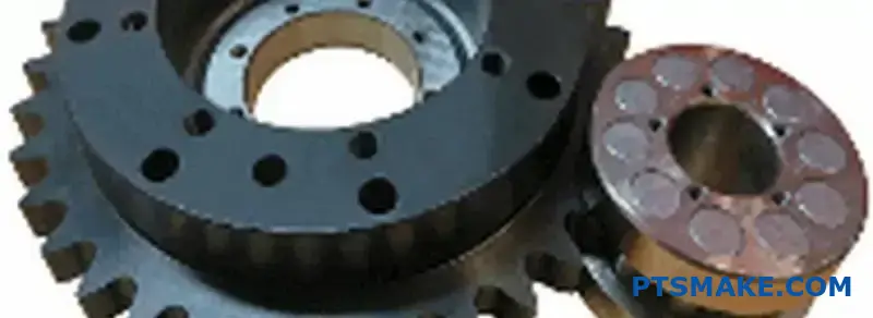
Nach unserer Erfahrung mit Kunden in der Fluidtechnikbranche ist Präzision nicht verhandelbar. Pumpen mit ineinander greifenden Stirnrädern, so genannte Zahnradpumpen, verlassen sich auf die konstante Volumenübertragung durch die Verzahnung. Die Konstruktion gewährleistet einen gleichmäßigen, nicht pulsierenden Durchfluss, der für Hydrauliksysteme entscheidend ist. Die Zahnräder müssen präzise sein, ein Service, auf den wir uns bei PTSMAKE durch CNC-Bearbeitung spezialisiert haben. Dies ist ein klassischer Fall, in dem die einfache Geometrie eines Stirnradgetriebes eine komplexe Geometrie übertrifft.
Fördersysteme
Förderbänder in Fabriken oder Lagern müssen gleichmäßig und zuverlässig laufen. Sie arbeiten mit mäßigen Geschwindigkeiten, bei denen Geräusche weniger eine Rolle spielen. Stirnradgetriebe liefern das erforderliche Drehmoment für den Antrieb der Bänder ohne die zusätzlichen Kosten und die Komplexität, die mit Axiallasten verbunden sind. Ihre Haltbarkeit gewährleistet eine lange Lebensdauer bei minimalem Wartungsaufwand. Dies ist entscheidend für den reibungslosen Betrieb von Produktionslinien.
| Anmeldung | Hauptgrund für die Wahl des Stirnrads |
|---|---|
| Waschmaschine | Geringe Kosten, Einfachheit |
| Zahnradpumpen | Präzise Positive Verdrängung12, Kein Axialschub |
| Fördergurte | Zuverlässigkeit, Kosten-Wirksamkeit |
| Elektrische Werkzeuge | Hohe Drehmomentübertragung, einfache Montage |
Stirnradgetriebe sind die beste Wahl für Anwendungen, bei denen Einfachheit, Kosteneffizienz und das Fehlen von Axialschub entscheidend sind. Sie eignen sich hervorragend für unkomplizierte Kraftübertragungssysteme wie einfache Getriebe, Pumpen und Förderanlagen und bieten Zuverlässigkeit und einfache Wartung.
Für welche Anwendungen sind schrägverzahnte Zahnräder die erste Wahl?
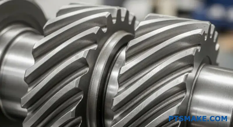
Wenn keine Kompromisse bei der Leistung gemacht werden dürfen, sind schrägverzahnte Getriebe die einzige Wahl. Ihr Design ist perfekt für Anwendungen, die eine reibungslose, leise Kraftübertragung erfordern. Denken Sie an Hochgeschwindigkeits- und Hochlastumgebungen.
Stirnradgetriebe können hier einfach nicht mithalten. Der allmähliche Eingriff der Schrägverzahnung reduziert Lärm und Vibrationen. Das macht sie in bestimmten Branchen unverzichtbar.
Leistungsstarke Anwendungen
Kfz-Getriebe
Bei Autos, insbesondere bei Elektrofahrzeugen, ist die Geräuschreduzierung entscheidend. Schrägverzahnte Getriebe sorgen für eine ruhige und sanfte Fahrt für die Fahrgäste.
Industrie-Getriebe
Für schwere Maschinen und Turbinen ist Zuverlässigkeit der Schlüssel. Schrägverzahnte Getriebe können höhere Lasten und Geschwindigkeiten bewältigen und gewährleisten eine langfristige Betriebsstabilität.
| Anmeldung | Schlüsselanforderung | Warum schrägverzahnt? |
|---|---|---|
| Automobilindustrie | Geräuscharmer Betrieb | Abgewinkelte Zähne reduzieren Lärm und Vibrationen. |
| Turbinen | Hochgeschwindigkeitsleistung | Sanftes Einrasten bei hohen Drehzahlen. |
| Industriell | Hohe Belastbarkeit | Ein größerer Zahnkontakt verteilt die Belastung. |
In der Debatte zwischen Stirnrädern und Schrägstirnrädern entscheidet die Anwendung über den Sieger. Während Stirnradgetriebe effizient und einfacher herzustellen sind, sind sie bei hohen Geschwindigkeiten laut. Dies ist auf den abrupten Kontakt zwischen den Zähnen zurückzuführen.
Schrägverzahnte Zahnräder lösen dieses Problem. Die abgewinkelten Zähne greifen allmählich über die gesamte Fläche des Zahnrads ein. Dies führt zu einer viel sanfteren und leiseren Kraftübertragung. Unsere Tests bei PTSMAKE zeigen durchweg eine deutliche Reduzierung von Lärm, Vibrationen und Rauheit (NVH).
Der technische Kompromiss
Dieser reibungslose Betrieb ist mit einem Kompromiss verbunden. Die abgewinkelten Zähne erzeugen Axialschub13, Eine Kraft, die die Zahnräder entlang ihrer Wellen auseinander drückt. Diese Kraft muss mit geeigneten Lagern, z. B. Axiallagern, abgefangen werden.
Dies erhöht die Komplexität und die Kosten der Konstruktion. Für Anwendungen, bei denen die Leistung im Vordergrund steht, ist dies jedoch eine notwendige technische Entscheidung. Eine Nichtbeachtung kann zu einem vorzeitigen Ausfall führen.
Anwendungsspezifische Vorteile
| Merkmal | Nutzen für die Automobilindustrie | Industrieller Nutzen |
|---|---|---|
| Reibungsloses Engagement | Erhöhter Fahrkomfort. | Geringerer Verschleiß der Maschinen. |
| High-Speed-Fähigkeit | Geeignet für moderne Motoren und Elektrofahrzeuge. | Unverzichtbar für Turbinen zur Stromerzeugung. |
| Höhere Belastbarkeit | Erhöhte Zuverlässigkeit der Übertragung. | Längere Lebensdauer von Hochleistungsgetrieben. |
Bei PTSMAKE beraten wir unsere Kunden bei diesen Abwägungen. Wir helfen ihnen bei der Auswahl des richtigen Getriebetyps und entwerfen die unterstützenden Systeme, um optimale Leistung und Haltbarkeit für ihre spezifische Anwendung zu gewährleisten.
Für Hochgeschwindigkeits- und Hochleistungssysteme wie Fahrzeuggetriebe und Industrieturbinen sind schrägverzahnte Getriebe unverzichtbar. Ihre Konstruktion gewährleistet einen reibungslosen, leisen Betrieb, trotz der zusätzlichen Komplexität, die durch die Bewältigung des Axialschubs entsteht. Stirnradgetriebe sind für diese anspruchsvollen Anwendungen einfach zu laut.
Wie unterscheidet sich die Schmierungsstrategie für gerad- und schrägverzahnte Zahnräder?
Zwar müssen alle Zahnräder geschmiert werden, aber die Wahl des Schmierstoffs ist keine Einheitsgröße, die für alle passt. Die Strategie unterscheidet sich erheblich, wenn man Stirnradgetriebe mit Schrägverzahnungen vergleicht.
Stirnradgetriebe funktionieren oft gut mit Allzweckschmierstoffen. Ihr geradverzahntes Design führt hauptsächlich zu einem Rollkontakt. Das bedeutet weniger Reibung und Wärmeentwicklung.
Bei schrägverzahnten Rädern ist die Gleitbewegung jedoch größer. Dies ist auf ihre schräg stehenden Zähne zurückzuführen. Diese Gleitbewegung kann an den Kontaktstellen höhere Drücke und Temperaturen erzeugen.
Wichtige Schmierstoff-Faktoren
| Getriebetyp | Primärer Kontakt | Anforderung an das Schmiermittel |
|---|---|---|
| Stirnrad | Rollender | Allgemeiner Zweck, niedrigere Viskosität |
| Stirnradgetriebe | Schieben und Rollen | Höhere Viskosität, EP-Additive |
Diese Unterscheidung ist für die langfristige Leistung entscheidend.
Die Rolle von Hochdruckadditiven
Die Gleitbewegung in Schrägzahnrädern ist der Hauptgrund für den unterschiedlichen Schmierstoffbedarf. Dieses Gleiten unter Last stellt eine Herausforderung dar, die Standardschmierstoffe nicht immer bewältigen können. Es erzeugt erhebliche Reibungswärme.
Diese Hitze kann den Ölfilm zwischen den Zähnen zerstören. Wenn dieser Film versagt, kommt es zu einem Metall-auf-Metall-Kontakt, der zu Abrieb und vorzeitigem Verschleiß führt. Dies ist eine häufige Fehlerart, die wir bei Anwendungen mit hoher Belastung beobachtet haben.
Um dies zu verhindern, benötigen Schmierstoffe für schrägverzahnte Getriebe oft spezielle Additive. Hier sind Schmierstoffe mit spezifischen Zusatzstoffe für extremen Druck (EP)14 nicht verhandelbar werden.
Wann sind EP-Zusätze notwendig?
Auf der Grundlage unserer Tests mit Kunden wird der Bedarf an EP-Zusätzen unter bestimmten Bedingungen deutlich.
| Betriebsbedingung | Schmiermittel für Stirnradgetriebe | Schmiermittel für Stirnradgetriebe |
|---|---|---|
| Niedrige Geschwindigkeit, niedrige Last | Standard-Getriebeöl | Standard-Getriebeöl |
| Hohe Geschwindigkeit, hohe Belastung | Standard-Getriebeöl | Öl mit EP-Zusätzen |
| Schockbelastung | Kann leichte EP benötigen | Erfordert robuste EP-Additive |
Diese Additive bilden eine chemische Schutzschicht auf der Getriebeoberfläche. Diese Schicht dient als letzte Verteidigungslinie, wenn der Ölfilm beeinträchtigt ist. Sie verhindert, dass die Zähne des Getriebes unter starkem Druck zusammenschweißen. Bei PTSMAKE prüfen wir stets die Betriebslasten, um die richtige Schmierstoffstrategie zu empfehlen.
Zwar benötigen beide Getriebearten eine Schmierung, doch die höheren Gleitkräfte in Schrägverzahnungen erfordern häufig Schmiermittel mit EP-Zusätzen. Diese Wahl ist entscheidend für die Vermeidung von Verschleiß und die Gewährleistung der Zuverlässigkeit des Antriebsstrangs, insbesondere bei schweren Lasten.
Wie empfindlich ist die Ausrichtung der Gänge im Vergleich zwischen den beiden?
Die Ausrichtung des Getriebes ist entscheidend für Leistung und Lebensdauer. Schon eine leichte Fehlausrichtung kann große Probleme verursachen.
Schrägverzahnte Zahnräder sind in der Regel empfindlicher in dieser Hinsicht. Ihre schrägen Zähne erfordern eine präzise Positionierung.
Ohne sie wird die Last nicht gleichmäßig verteilt. Dies führt zu Lärm, Vibrationen und vorzeitigem Ausfall. Sehen wir uns an, warum das passiert.
| Getriebetyp | Ausrichtungsempfindlichkeit | Hauptgrund |
|---|---|---|
| Stirnräder | Weniger empfindlich (zu parallel) | Voller Linienkontakt entlang der Zahnoberfläche. |
| Schraubenförmige Zahnräder | Empfindlicher | Ein schräger Kontakt erfordert eine perfekte Parallelität der Welle. |
Die kritische Natur der Wellenausrichtung
In jedem Getriebesystem ist eine perfekte Wellenausrichtung das Ziel. In der Realität gibt es jedoch immer kleine Abweichungen. Wie jeder Getriebetyp mit dieser Unvollkommenheit umgeht, ist ein Schlüsselfaktor in der Debatte zwischen Stirnrädern und Schrägstirnrädern.
Die Empfindlichkeit von Stirnrädern wird erklärt
Schrägverzahnte Zahnräder erreichen ihren reibungslosen, geräuscharmen Betrieb durch schrittweisen Zahneingriff. Der Kontakt beginnt an einem Ende des Zahns und bewegt sich über dessen Fläche.
Dieser allmähliche Kontakt ist eine Stärke, aber auch eine Schwäche. Wenn die Wellen falsch ausgerichtet sind, konzentriert sich die Belastung auf einen Teil des Zahns. Dadurch entstehen örtliche Druckpunkte, oder Spannungskonzentration15, was zu beschleunigtem Verschleiß und Lochfraß führt.
Bei unserer Arbeit bei PTSMAKE haben wir erlebt, dass Schrägstirnradsätze aufgrund kleiner Montagefehler frühzeitig ausfallen. Das daraus resultierende ungleichmäßige Verschleißmuster ist ein klares Zeichen für Ausrichtungsprobleme.
| Versatz Typ | Auswirkungen auf schraubenförmige Zahnräder | Auswirkungen auf Stirnräder |
|---|---|---|
| Parallel | Hoch. Verursacht eine Konzentration der Belastung an den Zahnenden. | Mäßig. Der Linienkontakt bleibt erhalten, aber ungleichmäßig. |
| Eckig | Sehr hoch. Verändert das Tragbild und die Belastung drastisch. | Hoch. Führt zu Kantenbelastung und hoher Beanspruchung. |
Stirnradverzehr
Stirnräder mit ihren geraden Zähnen verzeihen leichtere Fehlausrichtungen der parallelen Welle. Die Last wird über die gesamte Zahnfläche verteilt.
Sie sind zwar nicht immun, können aber kleinere Mängel besser verkraften, ohne dass es sofort zu einem katastrophalen Ausfall kommt. Allerdings ist eine winklige Fehlausrichtung immer noch sehr schädlich.
Zusammenfassend lässt sich sagen, dass schrägverzahnte Zahnräder eine höhere Präzision bei der Montage erfordern. Ihre Konstruktion, die einen reibungslosen Betrieb ermöglicht, macht sie auch empfindlicher gegenüber Fluchtungsfehlern. Stirnradgetriebe bieten mehr Toleranz, insbesondere bei Abweichungen von parallelen Wellen, was sie in einigen Anwendungen robuster macht.
Wie begrenzt die Betriebsgeschwindigkeit ihre jeweiligen Anwendungen?
Die Betriebsgeschwindigkeit ist ein entscheidender Faktor bei der Wahl zwischen Stirnrad- und Schrägverzahnung. Sie hat einen direkten Einfluss auf Geräusche, Vibrationen und die dynamischen Belastungen innerhalb eines Systems.
Bei Stirnrädern gibt es eine praktische Geschwindigkeitsgrenze. Ihr geradverzahntes Design verursacht einen abrupten Kontakt auf der ganzen Linie während des Eingriffs. Dadurch entstehen Aufprallkräfte, die mit zunehmender Geschwindigkeit ansteigen.
Dies ist eine wichtige Überlegung in der Debatte zwischen Stirnrädern und Schrägstirnrädern. Im Folgenden finden Sie einen kurzen Vergleich ihrer geschwindigkeitsbezogenen Merkmale.
| Merkmal | Stirnräder | Schraubenförmige Zahnräder |
|---|---|---|
| Geschwindigkeit Eignung | Gering bis mäßig | Hoch |
| Lärm bei Geschwindigkeit | Hoch | Niedrig |
| Auswirkungen auf die Vermaschung | Bedeutend | Minimal |
Dieses abrupte Einrasten ist der Grund, warum Stirnradgetriebe bei höheren Geschwindigkeiten laut werden und vibrieren.
Die Herausforderung der Geschwindigkeit mit Stirnrädern
Das Hauptproblem von Stirnradgetrieben bei hohen Drehzahlen ist ihre Geometrie. Die gesamte Stirnfläche des Zahns greift auf einmal ein. Stellen Sie sich das wie einen kleinen, schnellen Schlageffekt vor. Je schneller sich das Zahnrad dreht, desto häufiger und kräftiger werden diese Schläge.
Dies führt zu erheblichen dynamische Belastungen16, Dadurch wird die Verzahnung belastet und es entstehen hörbare Geräusche. Ab einer bestimmten Drehzahl können diese Vibrationen die Zuverlässigkeit und Leistung des gesamten Systems beeinträchtigen. Dadurch wird eine praktische Geschwindigkeitsgrenze für ihre Verwendung gesetzt.
Warum schrägverzahnte Getriebe bei hohen Geschwindigkeiten überragend sind
Schrägverzahnte Zahnräder überwinden diese Einschränkung auf elegante Weise. Ihre abgewinkelten Zähne sorgen dafür, dass der Kontakt an einem Ende des Zahns beginnt und sanft über die Fläche verläuft. Dieser allmähliche Eingriff eliminiert die für Stirnräder charakteristischen Stoßkräfte.
Dieses reibungslose Ineinandergreifen ermöglicht einen leiseren Betrieb und deutlich weniger Vibrationen. Bei den Projekten, die wir bei PTSMAKE bearbeiten, macht diese Eigenschaft Schrägverzahnungen zur Standardwahl für Anwendungen, die hohe Drehzahlen erfordern, wie z. B. in Automobilgetrieben oder Präzisionsindustriemaschinen.
| Geschwindigkeitsbereich | Bevorzugter Getriebetyp | Schlüssel Rechtfertigung |
|---|---|---|
| Gering bis mäßig | Stirnrad | Einfachheit und Kosteneffizienz. |
| Hoch | Stirnradgetriebe | Reibungsloser, leiser Betrieb und Zuverlässigkeit. |
Dieser grundlegende Unterschied im Engagement ist es, was ihre Anwendungsbereiche auszeichnet.
Stirnradgetriebe sind aufgrund der Aufprallkräfte und des Lärms, der durch ihren abrupten Zahneingriff entsteht, in ihrer Geschwindigkeit begrenzt. Schrägverzahnte Getriebe mit ihrem allmählichen Zahneingriff arbeiten sanft und leise, was sie für Hochgeschwindigkeitsanwendungen, bei denen Zuverlässigkeit und Geräuscharmut entscheidend sind, unentbehrlich macht.
Wie wählt man den richtigen Getriebetyp für eine Anwendung aus?
Die Auswahl der richtigen Ausrüstung erfordert einen strukturierten Prozess. Es geht nicht nur um eine einzige Spezifikation. Sie müssen mehrere Schlüsselfaktoren abwägen.
Dadurch wird sichergestellt, dass die endgültige Wahl alle Leistungsziele erfüllt. Ich beginne immer mit den primären Anwendungsanforderungen.
Wichtige Faktoren für die Entscheidungsfindung
Ein klarer Rahmen verhindert kostspielige Fehler. Berücksichtigen Sie diese fünf kritischen Bereiche, bevor Sie eine Entscheidung treffen. Jeder dieser Bereiche hat Auswirkungen auf die Eignung der Ausrüstung.
| Faktor | Beschreibung |
|---|---|
| Drehzahl (RPM) | Die erforderliche Betriebsdrehzahl. |
| Drehmoment | Die Rotationskraft, die das Getriebe übertragen muss. |
| Lärmpegel | Der akzeptable Geräuschpegel während des Betriebs. |
| Haushalt | Die Kostenbeschränkungen für die Komponente. |
| Platzbeschränkungen | Der für das Zahnradsystem verfügbare physische Raum. |
Ein schrittweiser Auswahlrahmen
Bei PTSMAKE führen wir unsere Partner durch einen systematischen Prozess. Er beginnt mit der Definition der primären Anforderungen. Dadurch wird sichergestellt, dass das richtige Getriebe sowohl für die Leistung als auch für die Herstellbarkeit ausgewählt wird.
Ein gemeinsamer Ausgangspunkt ist die Wahl zwischen Stirnrädern und Schrägstirnrädern. Stirnradgetriebe sind effizient und kostengünstig für mittlere Geschwindigkeiten. Schrägverzahnte Getriebe laufen ruhiger und leiser und sind daher ideal für Hochgeschwindigkeits- oder geräuschempfindliche Anwendungen.
Allerdings ist die Entscheidung selten so einfach. Sie müssen berücksichtigen, wie die verschiedenen Getriebetypen in allen Kriterien abschneiden. Bei Präzisionsanwendungen spielen auch Faktoren wie Rückwirkung17, was kritisch sein kann.
Entscheidungsmatrix für die Auswahl des Fanggeräts
Wir verwenden mit unseren Kunden häufig eine Entscheidungsmatrix. Dieses Instrument hilft dabei, die Kompromisse zwischen verschiedenen Arten von Fanggeräten zu visualisieren. Es bietet einen klaren, datengesteuerten Weg zur besten Lösung.
| Getriebetyp | Bewertung der Geschwindigkeit | Drehmoment Kapazität | Lärmpegel | Relative Kosten | Wirkungsgrad |
|---|---|---|---|---|---|
| Spur | Mittel | Mittel | Hoch | Niedrig | Sehr hoch |
| Wendel | Hoch | Hoch | Niedrig | Mittel | Hoch |
| Fase | Mittel | Mittel | Mittel | Hoch | Hoch |
| Wurm | Niedrig | Sehr hoch | Sehr niedrig | Mittel | Niedrig bis mittel |
Diese Matrix ist ein Ausgangspunkt. Ihre spezifische Anwendung wird das richtige Gleichgewicht bestimmen.
Ein strukturierter Entscheidungsrahmen vereinfacht die Auswahl von Getrieben. Durch die Bewertung von Anforderungen wie Geschwindigkeit, Drehmoment, Geräuschentwicklung, Budget und Platzbedarf können Sie systematisch den optimalen Getriebetyp für Ihre spezifischen Anforderungen ermitteln, um Rätselraten zu vermeiden und eine zuverlässige Leistung zu gewährleisten.
Wie wählt man das richtige Material für ein Zahnrad aus?
Die Wahl des richtigen Zahnradmaterials ist eine wichtige Entscheidung. Sie wirkt sich direkt auf die Leistung, die Lebensdauer und die Gesamtkosten Ihres Produkts aus. Die spezifischen Anforderungen Ihrer Anwendung müssen Ihre Auswahl leiten.
Denken Sie an Faktoren wie Belastung, Geschwindigkeit und Betriebsumgebung. Ein Stahlzahnrad mit hohem Drehmoment für ein Fahrzeuggetriebe hat ganz andere Anforderungen als ein geräuscharmes Kunststoffzahnrad in einem Bürodrucker.
Hier ist ein kurzer Überblick für den Einstieg:
| Material-Kategorie | Hauptvorteil | Allgemeiner Anwendungsfall |
|---|---|---|
| Stahl-Legierungen | Hohe Festigkeit und Langlebigkeit | Kfz-Getriebe |
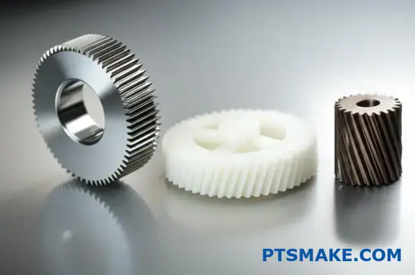
| Kunststoffe | Geräuscharmut und Korrosionsbeständigkeit | Bürogeräte, Medizinische Geräte |
| Bronze-Legierungen | Geringe Reibung und Anpassungsfähigkeit | Schneckenradantriebe |
Dieser Leitfaden soll Ihnen helfen, diese Optionen für Ihr Projekt zu nutzen.
Lassen Sie uns in einen praktischen Leitfaden für die Materialauswahl eintauchen. Die beste Wahl ist immer ein Gleichgewicht zwischen Leistung und Budget. Bei PTSMAKE beginnen wir oft mit der Analyse der Einsatzkräfte und der Umgebung, um dieses Gleichgewicht zu finden.
Stahllegierungen für hochbeanspruchte Arbeitsplätze
Wenn es um hohe Festigkeit und Haltbarkeit geht, ist Stahl das Material der Wahl. Er verträgt hohe Belastungen und Abnutzung außergewöhnlich gut, egal ob es sich um Gerad- oder Schrägzahnräder handelt. Durch Wärmebehandlung lassen sich seine Eigenschaften noch erheblich verbessern.
| Stahl-Legierung | Am besten für | Hauptmerkmal |
|---|---|---|
| 4140 Stahl | Hohes Drehmoment und Zähigkeit | Fähigkeit zur Durchhärtung |
| 8620 Stahl | Aufprall und Oberflächenverschleiß | Hervorragend geeignet für die Einsatzhärtung |
Kunststoffe für spezialisierte Anwendungen
Unterschätzen Sie Kunststoffe nicht. Sie lösen gängige Probleme wie Lärm, Korrosion und die Notwendigkeit einer externen Schmierung. Unsere Tests haben ergeben, dass sie sich ideal für Anwendungen mit geringerer Belastung eignen, bei denen diese Faktoren kritisch sind.
Die einzigartige tribologische Eigenschaften18 von Kunststoffen machen sie in vielen modernen Designs unverzichtbar.
Beliebte Kunststoffoptionen
- Delrin (Acetal): Bekannt für seine geringe Reibung und hervorragende Dimensionsstabilität. Wir empfehlen es für bewegliche Präzisionsteile.
- Nylon: Es bietet eine gute Zähigkeit und chemische Beständigkeit. Außerdem dämpft es hervorragend Lärm und Vibrationen.
Bronze für reibungsarmes Zusammenfügen
Bronzelegierungen sind eine klassische Wahl für bestimmte Zahnradtypen. Sie werden besonders häufig für Schneckenräder verwendet, die mit Stahlschnecken zusammenarbeiten. Diese Werkstoffpaarung bietet eine sehr geringe Reibung und verhindert das Festfressen unter schweren Lasten.
Die Wahl des richtigen Zahnradmaterials ist ein Kompromiss. Stahl bietet Festigkeit für hohe Lasten. Kunststoffe bieten einen leisen, korrosionsbeständigen Betrieb für leichtere Aufgaben. Bronze eignet sich hervorragend für spezielle Anwendungen mit geringer Reibung. Der Schlüssel liegt in der Abstimmung des Materials auf die speziellen Anforderungen Ihrer Anwendung.
Wie würden Sie ein lautes Stirnradgetriebe so umgestalten, dass es leiser wird?
Ein geräuschvoller Stirnradantrieb ist eine häufige technische Herausforderung. Die effektivste Lösung erfordert oft eine komplette Neukonstruktion. Einfaches Austauschen von Teilen ist nicht genug.
Wir ersetzen die lauten Stirnräder durch schrägverzahnte Zahnräder. Diese Änderung reduziert den Lärm erheblich. Sie erfordert jedoch eine sorgfältige Neukonstruktion des gesamten Systems.
Das Wichtigste ist, die Unterschiede zwischen Stirnrädern und Schrägstirnrädern zu verstehen. Die schrägen Zähne von Schrägzahnrädern greifen allmählich ein, weshalb sie leiser laufen.
| Getriebetyp | Verlobung | Lärmpegel |
|---|---|---|
| Stirnrad | Abrupt | Hoch |
| Stirnradgetriebe | Schrittweise | Niedrig |
Diese Neukonstruktion umfasst Änderungen der Geometrie, der Lager und des Gehäuses.
Wenn wir einen Antrieb neu konzipieren, um ihn leiser zu machen, gehen wir über einen einfachen Getriebewechsel hinaus. Der Übergang von Stirnrädern zu Schrägstirnrädern ist eine grundlegende technische Änderung. Er wirkt sich auf die gesamte mechanische Baugruppe aus.
Neuberechnung der Zahnradgeometrie
Der erste Schritt ist die Neuberechnung der Zahnradgeometrie. Die Einführung eines Schrägungswinkels ändert alles. Sie bewirkt einen sanfteren, allmählicheren Zahneingriff. Dies ist der Hauptgrund für die Geräuschreduzierung. Wir müssen den Eingriffswinkel und das Zahnprofil anpassen, um den Kontakt zu optimieren und den Verschleiß zu minimieren.
Neue Lager spezifizieren
Stirnräder erzeugen in erster Linie radiale Belastungen. Schrägverzahnte Räder erzeugen aufgrund ihrer schrägen Zähne sowohl radiale als auch Axialer Schub19. Diese neue Kraft muss beherrscht werden. Standardkugellager können ausfallen. Wir müssen Lager spezifizieren, die in der Lage sind, Axiallasten zu bewältigen, wie z. B. Kegelrollenlager oder Schrägkugellager.
Modifizierung des Gehäuses
Die neuen Lager und Axialkräfte erfordern Änderungen am Gehäuse. Das Gehäuse muss steif genug sein, um die neue Lageranordnung zu tragen. Es muss eine Durchbiegung der Welle unter Last verhindern. Bei PTSMAKE konstruieren wir das Gehäuse häufig neu, um eine präzise Ausrichtung und langfristige Zuverlässigkeit zu gewährleisten.
| Design-Aspekt | Stirnradantrieb | Neugestaltung von Stirnrädern |
|---|---|---|
| Primärlast | Radial | Radial & Axial |
| Lager Typ | Einfaches Kugellager | Kegel-/Angular-Kontakt |
| Gehäuse | Standard Steifigkeit | Verstärkt für Schubkraft |
| Lärm | Hoch | Niedrig |
Die Umstellung auf schrägverzahnte Getriebe für einen leisen Betrieb ist nicht einfach nur ein Austausch. Es handelt sich um eine umfassende Neugestaltung, die eine neue Geometrie, spezielle Lager für den Schubbetrieb und ein modifiziertes Gehäuse umfasst. Dies gewährleistet ein wirklich leises und zuverlässiges System.
Wie kann man ein Getriebe so optimieren, dass es möglichst wenig wiegt?
Bei kritischen Anwendungen wie der Luft- und Raumfahrt kommt es auf jedes Gramm an. Fortschrittliche Strategien sind unerlässlich. Wir gehen über das grundlegende Design hinaus, um ein minimales Gewicht zu erreichen.
Leistungsstarke Materialien
Die Wahl von Materialien wie hochfesten Stahllegierungen oder Titan ist der erste Schritt. Diese bieten ein besseres Verhältnis von Festigkeit zu Gewicht.
Fortgeschrittene Wärmebehandlungen
Verfahren wie Nitrieren oder Aufkohlen härten die Zahnradoberfläche. Dies erhöht die Belastbarkeit. So kann ein kleineres, leichteres Zahnrad die gleiche Aufgabe erfüllen.
Optimierung von Zahnradrohlingen
Das Ausweben des Zahnradrohlings ist eine Schlüsseltechnik. Wir entfernen strategisch Material aus dem Zahnradkörper. Dies reduziert das Gewicht, ohne den kritischen Zahnbereich zu beeinträchtigen.
| Strategie | Auswirkungen auf das Gewicht | Betrachtung |
|---|---|---|
| Fortschrittliche Materialien | Hoch | Höhere Materialkosten |
| Wärmebehandlung | Mittel | Zusätzlicher Prozessschritt |
| Gurtband | Hoch | Komplexe Bearbeitungen |
Fortschrittliche Gewichtsoptimierung erfordert einen ganzheitlichen Ansatz. Es geht darum, Materialwissenschaft, Wärmebehandlung und intelligentes geometrisches Design zu kombinieren, um ein Getriebe zu schaffen, das sowohl stark als auch unglaublich leicht ist.
Optimierung der Kernstruktur des Getriebes
Das Ausstechen eines Zahnradrohlings ist mehr Kunst als Wissenschaft. Dabei werden Materialtaschen aus der zentralen Scheibe des Zahnrads herausgearbeitet. Dadurch wird nicht benötigte Masse entfernt. Das Ziel ist es, eine speichenähnliche oder gewebte Struktur zu schaffen. Dadurch bleibt die Steifigkeit erhalten, während das Gewicht drastisch reduziert wird. Bei früheren Projekten von PTSMAKE haben wir auf diese Weise eine erhebliche Gewichtsreduzierung erzielt.
| Getriebetyp | Relatives Gewicht | Komplexität |
|---|---|---|
| Rohling | 100% | Niedrig |
| Webbed Blank | 60-75% | Hoch |
Zahnprofil und Zahnfestigkeit
Neben dem Rohling sind Änderungen des Zahnprofils von entscheidender Bedeutung. Eine subtile Anpassung wie das Hinzufügen von Krönung20 kann sicherstellen, dass die Last auch bei leichten Fluchtungsfehlern gleichmäßig über die Zahnfläche verteilt wird. Dies verhindert Spannungskonzentrationen an den Zahnenden.
Diese verbesserte Lastverteilung bedeutet, dass das Getriebe mehr Belastung aushalten kann. Daher können wir es von vornherein kleiner und leichter gestalten. Dieses Prinzip ist ein wichtiger Gesichtspunkt in der Debatte zwischen Stirnrädern und Schrägstirnrädern, da beide Typen unterschiedlich auf solche Modifikationen reagieren. Durch die Kombination dieser konstruktiven Verbesserungen mit überlegenen Werkstoffen und Wärmebehandlungen liefern wir erstklassige, leichte Zahnräder für anspruchsvolle Branchen.
Die Optimierung für minimales Gewicht beinhaltet die Verwendung hochfester Materialien und fortschrittlicher Wärmebehandlungen. Durch eine intelligente Konstruktion, wie z. B. das Aussteifen des Zahnradrohlings und die Änderung des Zahnprofils, wird nicht benötigte Masse entfernt, ohne die strukturelle Integrität oder Leistung des Zahnrads zu beeinträchtigen.
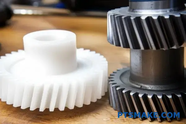
Wann würden Sie sich bewusst für ein Kunststoffstirnrad gegenüber Stahl entscheiden?
Es ist leicht zu glauben, dass Stahl immer besser ist. Er ist stärker, richtig? Aber Stärke ist nicht der einzige Faktor. Für viele Anwendungen ist ein Stirnradgetriebe aus Kunststoff die intelligentere und effizientere Wahl.
Das gilt besonders, wenn sich die Prioritäten verschieben. Denken Sie an Geräuscharmut, Selbstschmierung oder Korrosionsbeständigkeit. In diesen Fällen ist Kunststoff oft besser als Metall. Auch die Kosten sind ein wichtiger Faktor.
| Merkmal | Kunststoffgetriebe Vorteil | Stahlgetriebe Vorteil |
|---|---|---|
| Lärm | Sehr niedrig | Kann hoch sein |
| Schmierung | Selbstschmierend | Erfordert externes Schmiermittel |
| Kosten | Geringer, vor allem bei großen Mengen | Höhere Material- und Bearbeitungskosten |
| Gewicht | Leichtgewicht | Schwer |
Mehr als brachiale Stärke: Anwendungsspezifische Auswahlmöglichkeiten
Bei unserer Arbeit bei PTSMAKE beraten wir unsere Kunden bei der Materialauswahl. Es geht darum, das Material auf die reale Umgebung abzustimmen. Reine Stärke ist oft ein Overkill.
Büro- und Unterhaltungselektronik
Denken Sie an einen Drucker oder einen Scanner. Diese Geräte stehen in Büros oder zu Hause. Sie müssen leise laufen. Stahlzahnräder würden zu viel Lärm verursachen.
Stirnradgetriebe aus Kunststoff sind hier perfekt. Sie arbeiten fast geräuschlos. Außerdem benötigen sie kein Fett, das Papier verschmutzen oder die Elektronik beschädigen könnte. Ihr ausgezeichnetes tribologische Eigenschaften21 gewährleisten eine lange Lebensdauer ohne Wartung.
Umgebungen mit Korrosionsrisiko
Was ist mit einem Gerät, das in der Nähe von Wasser oder Chemikalien eingesetzt wird? Stahlzahnräder würden rosten und schnell versagen. Rostfreier Stahl ist eine Option, aber er ist teuer.
Kunststoffzahnräder sind von Natur aus korrosionsbeständig. Das macht sie ideal für lebensmittelverarbeitende Anlagen, medizinische Geräte oder Produkte für den Außenbereich. Sie bieten eine zuverlässige Leistung, die Stahl nicht bieten kann. Beim Vergleich von Stirnrädern mit Schrägverzahnung für diese Anwendungen ist das Material für die Langlebigkeit oft wichtiger als der Zahnradtyp.
| Anwendungsbereich | Hauptvorteil von Kunststoff |
|---|---|
| Bürodrucker | Geräuscharm, keine Schmierung erforderlich |
| Medizinische Geräte | Sterilisierbar, korrosionsbeständig |
| Lebensmittelverarbeitung | Chemische Beständigkeit, keine Kontamination |
| Spielzeuge & Gadgets | Kostengünstig, leicht, sicher |
Zusammenfassend lässt sich sagen, dass es bei der Entscheidung für Kunststoff statt Stahl nicht um einen Kompromiss geht. Es ist eine strategische Entscheidung. Sie legt den Schwerpunkt auf Kosteneffizienz, Geräuscharmut und Wartungsfreiheit bei Anwendungen, bei denen hohe Drehmomente und extreme Festigkeit nicht die Hauptanforderungen sind.
Analysieren Sie die Auswirkungen des Austauschs eines Stirnrads durch ein Schrägstirnrad auf den Wirkungsgrad.
Es ist ein weit verbreiteter Glaube, dass ein reibungsloserer Betrieb gleichbedeutend mit einer höheren Effizienz ist. In der Debatte um Stirnradgetriebe und Schrägverzahnung ist dies jedoch nicht immer der Fall.
Schrägverzahnte Zahnräder sorgen zwar für einen leiseren, allmählicheren Eingriff, aber ihre schräg stehenden Zähne bringen eine einzigartige Dynamik mit sich. Dadurch verändern sich die Kräfte, die im Spiel sind.
Die Quelle der Ineffizienz
Der Hauptunterschied liegt in der Art des Kontakts zwischen den Zähnen. Dies ist ein subtiler, aber kritischer Punkt für jeden Konstrukteur.
| Getriebetyp | Primärkontakt Bewegung | Ergebnis |
|---|---|---|
| Stirnrad | Rollen/Rutschen | Direkte Energieübertragung |
| Stirnradgetriebe | Erhöhtes Gleiten | Glatter, aber mehr Reibung |
Diese erhöhte Gleitwirkung entlang der Zahnoberfläche ist der Schlüssel. Sie erzeugt etwas mehr Reibung und Wärme im Vergleich zu einem Stirnrad.
Ein tieferer Blick auf Reibung und Kräfte
Lassen Sie uns diesen Kompromiss aufschlüsseln. Die Zähne eines Stirnrads greifen mit einer Bewegung ineinander, die größtenteils rollend und teilweise gleitend ist. Dies ist eine sehr effiziente Art der Kraftübertragung.
Schrägverzahnte Zahnräder haben aufgrund ihres Schrägungswinkels Zähne, die ineinander gleiten. Dieser kontinuierliche Gleitkontakt reduziert Geräusche und Stoßbelastungen, was ein wesentlicher Vorteil ist.
Diese Gleitbewegung erzeugt jedoch mehr Reibung als der hauptsächlich rollende Kontakt von Stirnrädern. Nach unseren internen Tests kann dies zu einem geringen Wirkungsgradverlust führen, der je nach Anwendung und Schmierung typischerweise im Bereich von 1-3% liegt.
Verstehen der Kompromisse
Die schraubenförmige Konstruktion erzeugt auch eine Kraft parallel zur Achse des Zahnrads. Diese Axialschub22 muss durch geeignete Lager bewältigt werden, die ihre eigenen Reibungsverluste in das System einbringen können. Die Wahl ist nicht immer einfach.
| Merkmal | Stirnrad | Stirnradgetriebe |
|---|---|---|
| Operation | Lauter | Leiser, geschmeidiger |
| Zahnkontakt | Leitung Kontakt | Schrittweises Engagement |
| Wirkungsgrad | Sehr hoch | Geringfügig niedriger |
| Axiale Belastung | Keine | Ja |
Bei PTSMAKE arbeiten wir oft mit unseren Kunden zusammen, um diese Feinheiten zu analysieren. Die Wahl des richtigen Getriebetyps hängt ganz von den spezifischen Prioritäten der Anwendung ab - Geräuschpegel, Tragfähigkeit oder maximale Effizienz.
Schrägverzahnte Getriebe bieten eine gleichmäßigere und leisere Leistung. Ihre schräg stehenden Zähne erhöhen jedoch die Gleitreibung. Dies führt zu einem geringfügigen, aber wichtigen Effizienznachteil im Vergleich zur direkteren Abrollbewegung von Stirnrädern.
Mit PTSMAKE erhalten Sie kompetente Lösungen für Stirnrad- und Schrägverzahnungen
Sind Sie bereit für Präzisionsgetriebelösungen? Gehen Sie eine Partnerschaft mit PTSMAKE ein, wenn es um kundenspezifische Stirnrad- und Schrägverzahnungen geht, die nach Ihren anspruchsvollen Standards entwickelt werden. Senden Sie jetzt Ihre Anfrage und erleben Sie zuverlässige Kommunikation, enge Toleranzen, kurze Lieferzeiten und ein echtes Engagement für Ihren Erfolg.

Verstehen Sie, welche entscheidende Rolle dieser Kreis bei der Definition des gesamten Evolventen-Zahnprofils spielt. ↩
Erfahren Sie, wie Sie diese Kraft für eine optimale Konstruktion und Langlebigkeit des Getriebesystems nutzen können. ↩
Erfahren Sie, wie dieses kritische geometrische Merkmal die Kraftverteilung und den Wirkungsgrad des Getriebes beeinflusst. ↩
Erforschen Sie genauer, wie verschiedene Kraftvektoren in Getrieben zusammenwirken. ↩
In unserem ausführlichen Leitfaden erfahren Sie, wie sich die Zahnradgeometrie auf die Leistung auswirkt. ↩
Verstehen, wie diese mechanische Eigenschaft die Vibrations- und Geräuschpegel in Getrieben beeinflusst. ↩
Erfahren Sie, wie die progressive Berührungslinie der Schrägverzahnung für eine sanftere und leisere Kraftübertragung sorgt. ↩
Verstehen Sie, wie sich diese Kraft auf die Konstruktion von Getrieben auswirkt und welche Lager erforderlich sind, um sie effektiv zu bewältigen. ↩
Verstehen Sie, wie die Analyse der Oberflächenspannung einen vorzeitigen Ausfall des Getriebes verhindern kann. ↩
Verstehen, wie diese Kraft die Konstruktion des Getriebes und die Auswahl der geeigneten Lager beeinflusst. ↩
Erfahren Sie, wie sich diese Kraft auf die Konstruktion und Langlebigkeit von Getrieben auswirkt. ↩
Erfahren Sie, wie diese Pumpen mithilfe präziser Zahnradmechanik Flüssigkeiten mit außergewöhnlicher Genauigkeit bewegen. ↩
Erfahren Sie, wie Sie diese Kraft in Ihren Entwürfen berechnen und verwalten können. ↩
Entdecken Sie, wie diese chemischen Additive katastrophale Getriebeausfälle unter extremen Belastungen verhindern. ↩
Erfahren Sie, wie sich die Spannungskonzentration auf die Materialermüdung und die Lebensdauer von Bauteilen auswirkt. ↩
Verstehen Sie, wie sich diese variablen Kräfte auf die Langlebigkeit der Getriebe und die Systemleistung auswirken. ↩
Erfahren Sie mehr über Getriebespiel und dessen Minimierung bei hochpräzisen CNC-Bearbeitungsanwendungen. ↩
Erfahren Sie, wie Reibungs-, Verschleiß- und Schmierungseigenschaften die Leistung und Lebensdauer Ihres Getriebes bestimmen. ↩
Verstehen Sie, wie sich diese Kraft auf die Konstruktion von Getrieben und die Auswahl von Lagern auswirkt, um eine optimale Leistung zu erzielen. ↩
Entdecken Sie, wie diese subtile Zahnmodifikation den Zahneingriff drastisch verbessern und die Lebensdauer verlängern kann. ↩
Erfahren Sie mehr darüber, wie sich Reibung, Verschleiß und Schmierung auf die Leistung von Zahnradmaterialien auswirken. ↩
Verstehen Sie, wie diese Kraft die Wahl der Lager und die Konstruktion des Systems beeinflusst. ↩