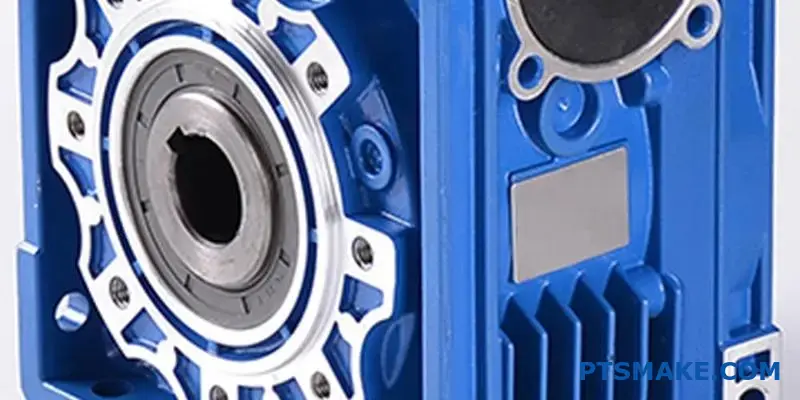
Sie sind dabei, ein Getriebesystem neu zu konstruieren, und die Stirnräder verursachen einen inakzeptablen Geräuschpegel. Der Zeitplan für Ihr Projekt ist eng, Ihr Budget ist begrenzt und der Wechsel zu schrägverzahnten Zahnrädern bedeutet, dass das gesamte Lagersystem und das Gehäuse neu konstruiert werden müssen.
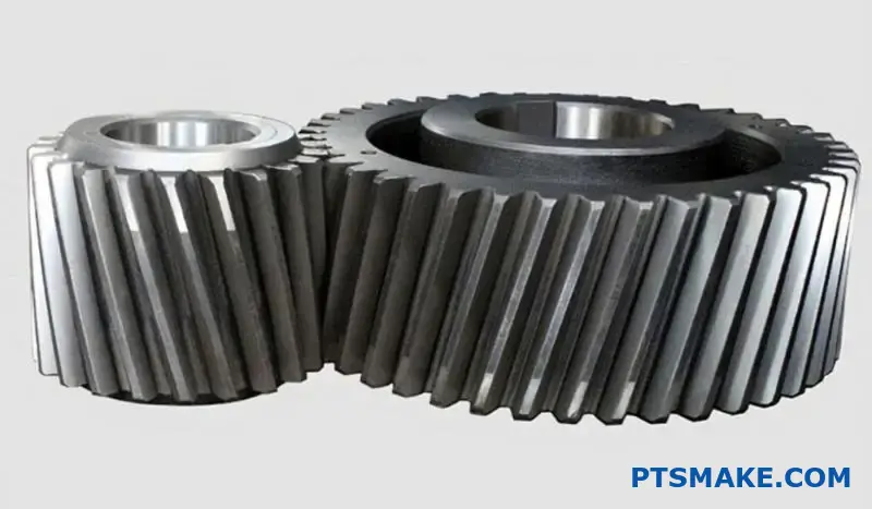
Stirnräder haben gerade Zähne, die parallel zur Wellenachse verlaufen, während Schrägzahnräder gewinkelte Zähne haben, die eine Schraubenlinie um den Zahnradumfang bilden. Dieser grundlegende Unterschied wirkt sich auf alles aus, vom Geräuschpegel und der Tragfähigkeit bis hin zu den Herstellungskosten und Lageranforderungen.
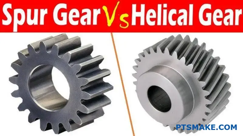
Durch meine Arbeit bei PTSMAKE habe ich Ingenieuren dutzende Male geholfen, genau diese Entscheidung zu treffen. Jeder Getriebetyp hat spezifische Stärken, die ihn für bestimmte Anwendungen ideal machen. Dieser Leitfaden führt Sie durch die technischen Unterschiede, Leistungsabwägungen und Auswahlkriterien, damit Sie die richtige Wahl für Ihr Projekt treffen können.
Was ist die grundlegende Geometrie, die einen Stirnradzahn definiert?
Das Geheimnis der Leistung eines Stirnradgetriebes ist nicht nur seine Form, sondern eine ganz bestimmte Kurve. Diese Kurve ist die Grundlage der Konstruktion.
Das unvollständige Profil
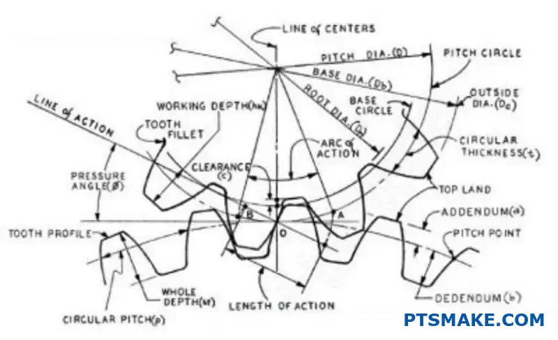
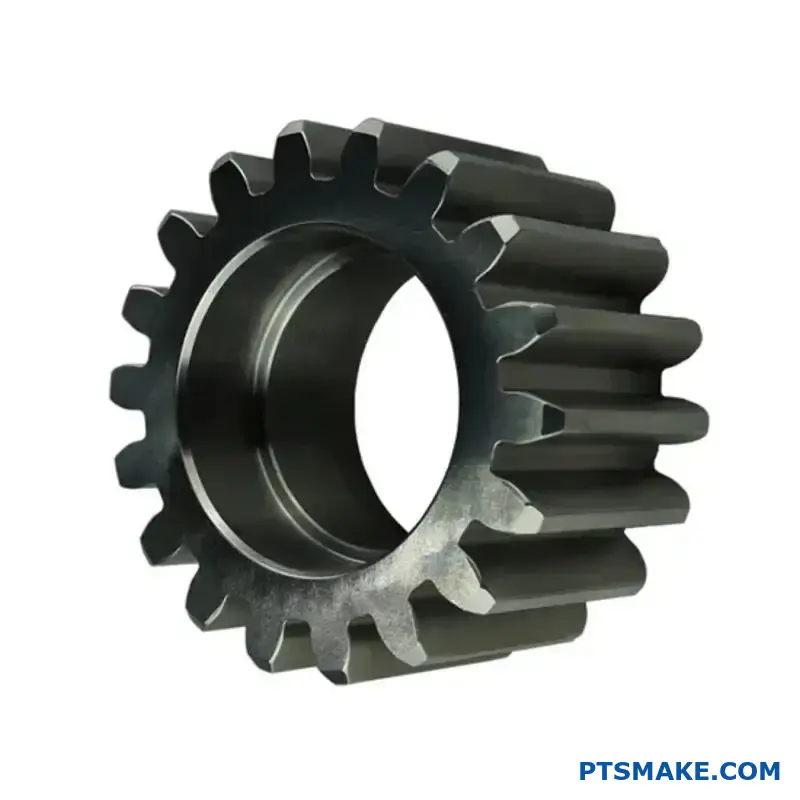
Das Zahnprofil eines modernen Stirnrads ist im Kern eine Evolventenkurve. Stellen Sie sich vor, Sie wickeln eine Schnur von einem Zylinder ab.
Diese spezielle Geometrie ist entscheidend. Sie sorgt dafür, dass beim Ineinandergreifen der Zahnräder die Drehzahl vollkommen konstant bleibt. Das verhindert Ruckeln und ungleichmäßigen Kraftfluss.
| Merkmal Geometrie | Zweck |
|---|---|
| Evolventenkurve | Konstantes Geschwindigkeitsverhältnis |
| Gerader Zahn | Axiale Leistungsübertragung |
| Richtige Abstände | Reibungsloses Engagement |
Wie der Involute einen reibungslosen Betrieb gewährleistet
Die Evolventenform ist nicht willkürlich. Es handelt sich um ein präzises mathematisches Profil, das vor allem aus einem Grund entwickelt wurde: um ein konstantes Geschwindigkeitsverhältnis zwischen den ineinander greifenden Zahnrädern zu gewährleisten. Dies ist ein unverzichtbares Prinzip für eine effiziente Kraftübertragung.
Die Magie des Normalen
Wenn sich zwei Zahnräder berühren, verläuft die gemeinsame Normale (eine Linie senkrecht zu den Oberflächen im Berührungspunkt) immer durch einen festen Punkt. Dieser Festpunkt wird als Wälzpunkt bezeichnet.
Diese gleichmäßige Geometrie sorgt dafür, dass das treibende Zahnrad das angetriebene Zahnrad mit gleichmäßiger Geschwindigkeit schiebt. Während des Eingriffs gibt es keine Beschleunigungen oder Verlangsamungen. Dies ist ein wesentlicher Unterschied beim Vergleich von Stirnradgetriebe im Vergleich zu Schrägstirnrädernda beide für einen reibungslosen Betrieb auf dieses Prinzip angewiesen sind.
Die Evolventenkurve wird aus einer Grundkreis1. Die Größe dieses Kreises ist grundlegend für die endgültige Zahnform und ihre Leistungsmerkmale. Bei unserer Arbeit bei PTSMAKE ist die richtige Geometrie entscheidend für die hochpräzisen Teile, auf die unsere Kunden angewiesen sind.
| Design-Aspekt | Konsequenz der involuten Geometrie |
|---|---|
| Kontaktstelle | Bewegt sich entlang der Zahnoberfläche |
| Aktionsbereich | Bleibt konstant und tangiert beide Grundkreise |
| Geschwindigkeitsverhältnis | Bleibt in der gesamten Masche konstant |
Die Evolventenkurve ist die grundlegende Geometrie für eine Stirnradverzahnung. Dieses spezifische Profil ist für das Erreichen eines konstanten Geschwindigkeitsverhältnisses, das eine reibungslose, zuverlässige und effiziente Kraftübertragung zwischen den ineinander greifenden Zahnrädern gewährleistet, unerlässlich.
Wie verändert ein Schrägungswinkel die Eigenschaften eines Zahnrads grundlegend?
Der Schrägungswinkel ist das wichtigste Einzelmerkmal. Er unterscheidet ein Schrägzahnrad von einem Geradzahnrad. Er ist nicht nur eine optische Verbesserung.
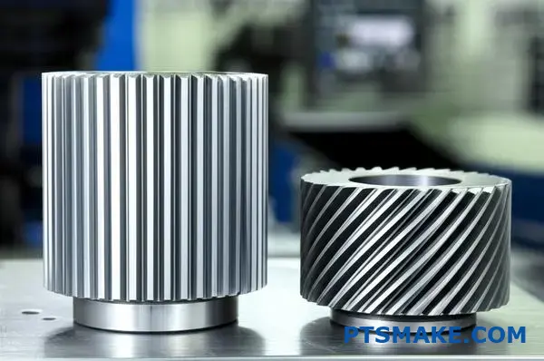
Stirnräder haben gerade Zähne. Sie greifen über ihre gesamte Fläche auf einmal ein. Dadurch entsteht ein abrupter, geradliniger Kontakt.
Schrägverzahnte Räder mit ihren abgewinkelten Zähnen greifen anders ein. Der Kontakt beginnt an einem Ende des Zahns. Er bewegt sich dann sanft über die Fläche, während sich das Zahnrad dreht.
Dieses schrittweise Engagement ist der Schlüssel.
| Merkmal | Stirnrad | Stirnradgetriebe |
|---|---|---|
| Zahnausrichtung | Gerade | Gewinkelt (Helix-Winkel) |
| Erster Kontakt | Vollständige Zeile | Kontaktperson |
| Verlobungsstil | Abrupt | Allmählich und sanft |
Die Mechanik des schrittweisen Engagements
Dieses allmähliche Ineinandergreifen ändert alles. Im Gegensatz zum plötzlichen Aufprall bei Stirnrädern gleiten die Schrägzähne ineinander. Die Last wird schrittweise aufgebracht, nicht auf einmal. Dadurch werden Stöße und Vibrationen erheblich reduziert.
Das Ergebnis ist ein wesentlich leiserer Betrieb. Das ist einer der Hauptgründe, warum Konstrukteure schrägverzahnte Getriebe den Stirnrädern vorziehen. Bei früheren Projekten von PTSMAKE hat der Wechsel zu schrägverzahnten Getrieben die Betriebsgeräusche deutlich reduziert. Dies ist für medizinische Geräte und Unterhaltungselektronik von entscheidender Bedeutung.
Dieser schräge Kontakt hat jedoch einen Nebeneffekt. Er erzeugt Axialschub2eine Kraft, die parallel zur Achse des Zahnrads verläuft. Diese Kraft ist bei Stirnrädern nicht vorhanden und muss bewältigt werden. Die richtige Auswahl der Lager ist entscheidend, um diese Belastung zu bewältigen und einen vorzeitigen Ausfall zu verhindern.
Dieser Kompromiss ist der Kern der Debatte über Stirnradgetriebe im Vergleich zu schrägverzahnten Getrieben.
| Aspekt des Engagements | Vorteil | Nachteil |
|---|---|---|
| Allmählicher Kontakt | Sanfterer, leiserer Betrieb | Erzeugt axiale Schubkraft |
| Gewinkelte Zähne | Höherer Gesamtberührungsgrad | Erfordert robuste Lager |
| Verteilung der Last | Erhöhte Tragfähigkeit | Komplexere Fertigung |
Eine Verschiebung der Lastverteilung
Dieser allmähliche Eingriff bedeutet auch, dass die Last zu jedem Zeitpunkt auf mehrere Zähne verteilt ist. Dies steht im Gegensatz zu Stirnrädern, bei denen ein oder zwei Zähne die gesamte Last tragen. Dank dieser Teilungsfähigkeit können Schrägzahnräder größere Lasten bewältigen und haben eine längere Lebensdauer.
Der Schrägungswinkel verändert den Zahnradkontakt grundlegend von einer abrupten Linie zu einem glatten, progressiven Bereich. Diese Verschiebung ist die Quelle der Vorteile in Bezug auf Geräusch und Tragfähigkeit, bringt aber auch die Herausforderung des Axialschubs mit sich.
Welche Kräfte wirken auf einen einzelnen Stirnradzahn während des Eingriffs?
Um wirklich zu verstehen, was beim Zahneingriff passiert, müssen wir die Gesamtkraft aufschlüsseln. Diese Kraft wirkt nicht geradeaus. Sie wirkt in einem Winkel zur Zahnoberfläche.
Ingenieure vereinfachen dies, indem sie die Kraft in zwei Hauptkomponenten aufteilen. Dies erleichtert die Analyse und Konstruktion erheblich. Dies sind die tangentialen und radialen Kräfte. Beide haben eine sehr unterschiedliche Wirkung auf das Zahnradsystem.
Verstehen der Kraftkomponenten
Im Folgenden werden diese beiden Kräfte und ihre Hauptaufgaben in einem Getriebesystem kurz beschrieben.
| Kraftkomponente | Primäre Funktion | Wichtigste Auswirkungen |
|---|---|---|
| Tangentiale Kraft | Sendet Leistung | Erzeugt ein Drehmoment zum Antrieb der Last |
| Radiale Kraft | Trennt Gänge | Belastung von Lagern und Wellen |
Die "arbeitende" Kraft: Tangentialkomponente
Die tangentiale Kraft ist die Komponente, die die ganze nützliche Arbeit leistet. Sie wirkt tangential zum Teilkreis des Zahnrads. Dies ist die Kraft, die tatsächlich das Drehmoment überträgt und das angetriebene Zahnrad in Drehung versetzt. Wenn Sie mehr Drehmoment benötigen, haben Sie es mit einer größeren Tangentialkraft zu tun.
Die trennende Kraft: Radialkomponente
Die Radialkraft hingegen leistet keine nützliche Arbeit für die Kraftübertragung. Ihre Aufgabe ist es, die beiden Zahnräder entlang einer Verbindungslinie zwischen ihren Mittelpunkten auseinander zu drücken. Diese Trennkraft ist ein kritischer Faktor für die Konstruktion. Sie belastet direkt die Wellen und die Lager, die sie tragen.
Bei früheren Projekten von PTSMAKE haben wir erlebt, dass Konstruktionen scheiterten, weil die Lager nicht für die Aufnahme der Radiallasten ausgelegt waren. Dies ist ein entscheidender Unterschied in der Debatte zwischen Stirnrädern und Schrägstirnrädern, da Schrägstirnräder auch eine Axialkraft (Schubkraft) erzeugen.
Die Größe dieser Kräfte wird durch das Getriebe bestimmt Eingriffswinkel3. Ein größerer Winkel erhöht die Radialkraft im Verhältnis zur Tangentialkraft.
Übersicht über die Kraftrichtung
| Kraft | Richtung der Aktion | Konsequenz |
|---|---|---|
| Tangential | Tangente zum Teilkreis | Drehmomentübertragung |
| Radial | In Richtung Gear Center | Lagerbelastung |
The total force on a spur gear tooth is best understood by its tangential and radial components. The tangential force drives the machine, while the radial force creates loads on the shafts and bearings. Proper design accounts for both.
Welche neue Kraftkomponente wird durch die Schrägverzahnung eingeführt?
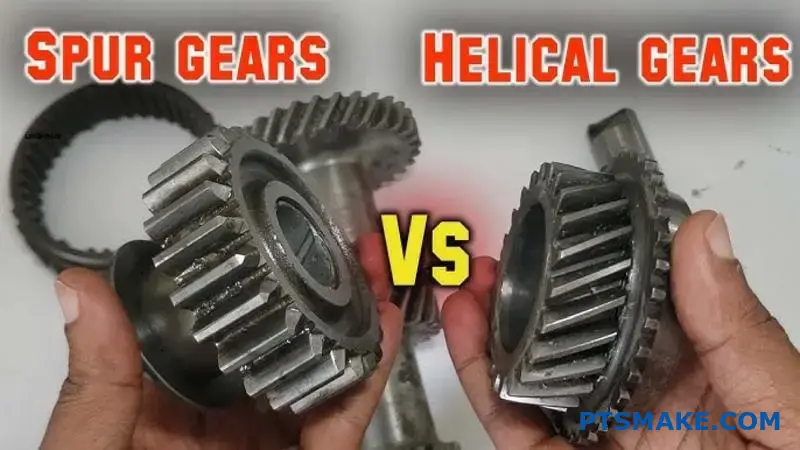
Helical gears introduce a significant force component not found in spur gears: axial thrust. This force acts parallel to the gear’s axis, essentially pushing the gear sideways.
Its origin lies in the angled teeth of the gear.
A Key Design Difference
When helical teeth mesh, the contact creates a force that is not perpendicular to the shaft. This creates the axial component.
| Getriebetyp | Primary Forces | New Force Component |
|---|---|---|
| Stirnrad | Radial, Tangential | Keine |
| Stirnradgetriebe | Radial, Tangential | Axialschub |
This new force requires careful management in your design.
The Physics Behind Axial Thrust
The helix angle is the direct cause of axial thrust. As power is transmitted, the force on the tooth surface is perpendicular to the tooth itself. Because the tooth is at an angle, this force resolves into two key components.
One is the tangential force, which drives the rotation. The other is the axial force, which pushes along the shaft. This is a core concept when comparing spur gears vs helical gears. The greater the helix angle, the larger the axial thrust for a given torque.
Calculating the Impact
This thrust isn’t a minor issue. It must be countered by appropriate bearings, such as tapered roller bearings or thrust bearings. Ignoring it can lead to premature bearing failure and system misalignment.
The total load on the tooth creates a resultierende Kraft4 that is a combination of these components. In our work at PTSMAKE, we precisely calculate these loads to ensure every component we manufacture performs reliably within the final assembly.
Helix Angle’s Direct Effect
| Helix-Winkel | Relative Axial Thrust |
|---|---|
| 15° | Niedrig |
| 30° | Mittel |
| 45° | Hoch |
This relationship is crucial for engineers. Selecting a higher helix angle for smoother operation comes with the trade-off of managing greater axial loads.
Helical gears introduce axial thrust due to their angled teeth. This force is directly proportional to the transmitted torque and the tangent of the helix angle. Proper bearing selection is essential to manage this load, a critical consideration absent in spur gear systems.
Wie wird das "Kontaktverhältnis" bei gerad- und schrägverzahnten Rädern definiert?
Contact ratio is a key gear metric. It defines the average number of tooth pairs in contact at any given time. A higher ratio means more teeth share the load.
This results in smoother power transmission. It also reduces noise and vibration significantly.
Spur vs. Helical Contact Ratios
The design of the gear teeth directly impacts this ratio. Let’s compare them.
| Getriebetyp | Typisches Übersetzungsverhältnis | Zahn Engagement |
|---|---|---|
| Stirnrad | 1.2 to 1.8 | Sequential, one pair engages as another disengages |
| Stirnradgetriebe | > 2.0 | Overlapping, multiple pairs in contact simultaneously |
This difference is fundamental to their performance.
Understanding the Mechanics of Contact Ratio
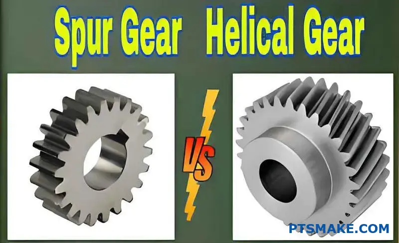
The difference in contact ratio comes down to tooth geometry. Spur gears have straight teeth. This means contact occurs along the entire tooth face at once. The engagement is abrupt.
Helical gears, however, have angled teeth. This creates a gradual engagement. Contact starts at one end of the tooth and sweeps across its face as the gear rotates.
Gradual Engagement in Helical Gears
This angled design extends the Kontaktweg5. It allows a new pair of teeth to start engaging before the previous pair has fully disengaged. This overlap is why their contact ratio is always greater than 2.0.
In our experience at PTSMAKE, this is a deciding factor. When clients debate Stirnradgetriebe im Vergleich zu Schrägstirnrädern for applications requiring low noise, the higher contact ratio of helical gears often makes them the clear choice.
Praktische Implikationen
A higher contact ratio distributes the load over more teeth. This reduces stress on individual teeth. It enhances load-carrying capacity and extends the gear’s operational life.
| Merkmal | Spur Gear (Lower Ratio) | Helical Gear (Higher Ratio) |
|---|---|---|
| Lastverteilung | Concentrated on 1-2 tooth pairs | Spread across 2+ tooth pairs |
| Lärmpegel | Höher | Unter |
| Vibration | Stärker ausgeprägt | Smoother operation |
| Stress on Teeth | Höher | Unter |
This makes helical gears ideal for high-speed, high-power applications where smoothness is essential.
Contact ratio measures simultaneous tooth engagement. Helical gears feature a higher, overlapping ratio compared to spur gears. This results in smoother, quieter operation and better load distribution, a critical distinction in gear selection.
Welches physikalische Phänomen ist die Hauptursache für Geräusche von Stirnrädern?
The heart of the issue is impact. The primary source of spur gear noise is the abrupt, full-face collision of teeth as they engage.
Unlike a smooth roll, this is a sudden event. This impact creates an instant pressure spike.
This pressure change causes vibrations. These vibrations travel through the gear material and surrounding air, which our ears detect as noise.
The process repeats with every single tooth meshing, creating a characteristic whine.
| Schritt | Physical Action | Ergebnis |
|---|---|---|
| 1. Engagement | Teeth collide abruptly | Sudden impact |
| 2. Impact | Energy transfer | Sharp pressure spike |
| 3. Propagation | Spike radiates outward | Vibration (Noise) |
This rapid, repetitive impact is the fundamental physical phenomenon we need to address.
The Mechanics of Abrupt Engagement
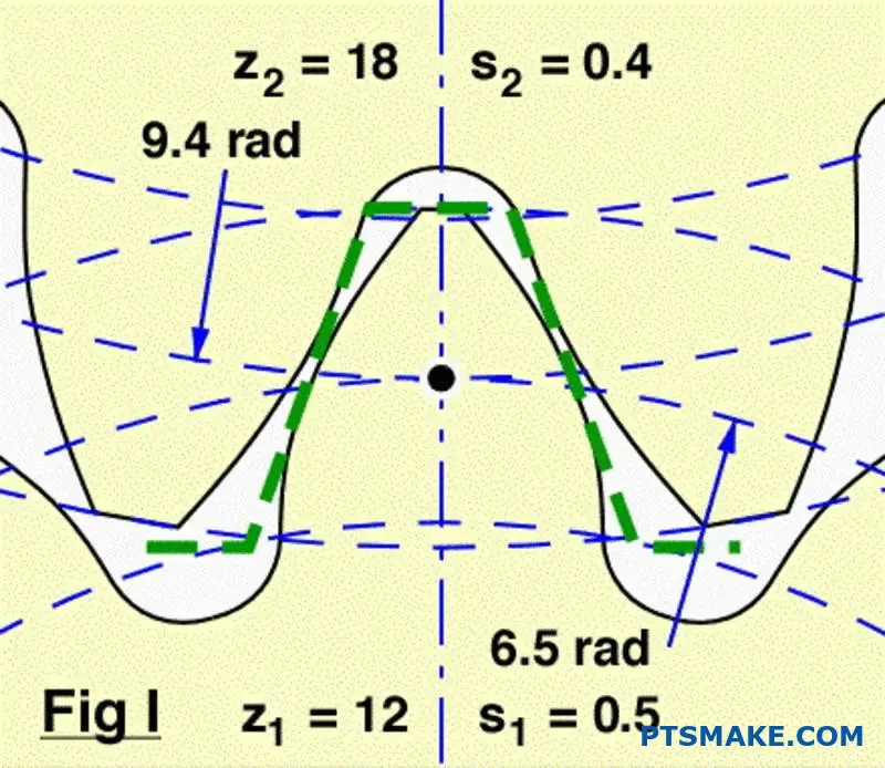
Let’s dig deeper into this impact. Spur gear teeth meet along their entire width simultaneously. This instantaneous line contact means there’s no gradual load transfer. It’s an all-or-nothing event.
This shock loading is the root cause. Each engagement acts like a tiny hammer strike on the system, creating a pressure wave.
From Vibration to Audible Noise
This pressure wave radiates away from the gears. When it travels through the air, we perceive it as sound. The frequency of this sound is directly tied to how often the teeth mesh.
At PTSMAKE, we often see how this lost energy impacts efficiency, not just acoustics. The noise you hear is wasted energy that could be doing useful work. A key factor is the tooth stiffness variation6 during the meshing cycle, which can amplify these vibrations.
This is a major point of difference in the spur gears vs helical gears debate. Helical gears engage gradually across the tooth face, which significantly softens this impact.
| Getriebetyp | Verlobungsstil | Ebene der Auswirkungen | Typical Noise |
|---|---|---|---|
| Stirnrad | Instantaneous, full-width | Hoch | Loud |
| Stirnradgetriebe | Gradual, angled | Niedrig | Quiet |
Our tests show this fundamental difference in engagement mechanics is the main reason for the noise disparity. Addressing the impact is key to quieter operation.
The primary source of spur gear noise is the sudden impact of teeth during engagement. This creates abrupt pressure variations and vibrations. The all-at-once nature of this contact is the core physical phenomenon responsible for the characteristic gear whine.
Warum sind schrägverzahnte Getriebe von Natur aus leiser als geradverzahnte?
The main reason is "gradual engagement." It’s a simple concept with a huge impact on noise.
Unlike spur gears, helical gear teeth are angled. This means they don’t mesh all at once.
The Secret of Smooth Contact
Contact begins at one point on the tooth. It then smoothly spreads across the face as the gears rotate.
This eliminates the sudden impact that causes noise. It creates a much smoother, quieter power transfer.
| Merkmal | Stirnrad | Stirnradgetriebe |
|---|---|---|
| Zahn Engagement | Abrupt, full-width | Gradual, point-to-line |
| Ebene der Auswirkungen | Hoch | Niedrig |
| Vibration | Bedeutend | Minimal |
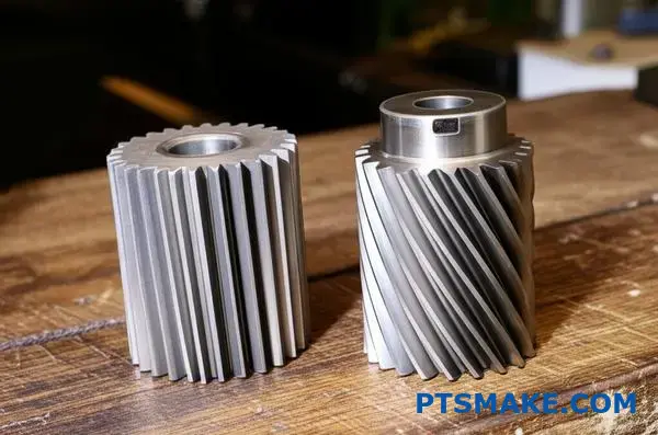
The Mechanics of Quiet Operation
Let’s dive deeper into this. Spur gears engage along the entire tooth face instantly. This abrupt contact creates a shock load, which is the primary source of gear noise and vibration. It’s like clapping your hands—a sudden, sharp sound.
From Impact to Flow
Helical gears change this dynamic entirely. The angled teeth ensure that as one part of a tooth is rotating out of mesh, another part is already beginning to engage. This overlap creates a continuous, uninterrupted flow of power.
This smooth handover between teeth is fundamental. It prevents the pressure spikes that generate noise.
Understanding the Contact Pattern
Die contact line7 on a helical gear tooth moves diagonally across its surface. This progressive engagement and disengagement is what makes the operation so quiet.
At PTSMAKE, we machine these angles with high precision. This ensures the load is distributed evenly, maximizing both quietness and gear life. When considering spur gears vs helical gears, this smooth transmission is often the deciding factor for our clients in noise-sensitive fields.
| Charakteristisch | Stirnrad | Stirnradgetriebe |
|---|---|---|
| Last Anwendung | Sudden Shock Load | Gradual, Distributed Load |
| Kraftübertragung | Interrupted at tooth level | Continuous, Smooth |
| Resulting Noise | High-frequency "whine" | Low, steady hum |
The angled teeth of helical gears allow for gradual engagement. This process minimizes the impact, shock, and vibration that make spur gears noisy. The result is a much smoother and quieter transfer of power.
Welches sind die wichtigsten Leistungsunterschiede zwischen diesen beiden Getrieben?
Choosing between spur and helical gears isn’t about which is better. It’s about understanding the specific trade-offs for your application. Each gear type excels in different areas.
Your decision impacts noise, load capacity, cost, and complexity. A structured comparison of spur gears vs helical gears can clarify the best choice. Here is a quick overview.
| Merkmal | Stirnrad | Stirnradgetriebe |
|---|---|---|
| Lärmpegel | Höher | Unter |
| Axialschub | Keine | Gegenwart |
| Kosten | Unter | Höher |
| Tragfähigkeit | Gut | Ausgezeichnet |
This framework helps balance performance against project constraints.
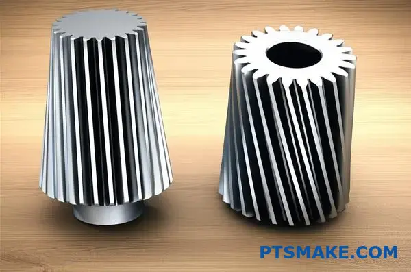
Making the right choice requires a deeper look at these performance axes. Each decision involves a compromise that can significantly affect your final product. At PTSMAKE, we guide clients through this process daily.
Noise vs. Axial Thrust
Helical gears are prized for quiet operation. Their angled teeth engage gradually, reducing the whining sound common with spur gears. This makes them ideal for consumer products or automotive transmissions.
However, this angled design creates Axialschub8. This is a force parallel to the gear’s axis. It requires thrust bearings to manage, adding complexity and cost to the assembly. Spur gears produce no such force.
Simplicity vs. Load Capacity
Spur gears are simpler to design and manufacture. Their straight teeth make them straightforward to cut and install. This simplicity translates to lower costs and easier maintenance.
Helical gears, with their complex geometry, can carry higher loads. The angled teeth provide a larger contact area, distributing stress more effectively. This is a key advantage in high-torque applications.
Cost vs. Smoothness
The manufacturing process directly impacts cost. The precision grinding needed for helical gears makes them more expensive than spur gears. This cost difference can be substantial in large production runs.
In return for the higher cost, helical gears deliver exceptionally smooth and consistent power transmission. This smoothness is crucial for precision machinery where vibration is undesirable.
Efficiency vs. Complexity
Spur gears are highly efficient, often reaching 98-99%. Their rolling contact generates very little friction.
Helical gears introduce a sliding motion between teeth, which can slightly reduce efficiency due to friction. However, this is often a minor trade-off for their superior performance in other areas.
The choice between spur and helical gears is a balancing act. Your priorities—be it low noise, high load capacity, budget, or design simplicity—will determine the ideal gear. There is no single "best" answer, only the best fit for your specific application.
Wie sieht es mit der Tragfähigkeit von Stirnrädern und Schrägstirnrädern aus?
When comparing spur gears vs helical gears of the same size and material, helical gears consistently win on load-carrying capacity. This isn’t by a small margin either.
The difference comes from their fundamental design. Spur gears engage abruptly across the entire tooth face at once.
Helical gears, with their angled teeth, engage gradually. This smoother transition distributes the load more effectively, allowing for higher performance under identical conditions.
| Getriebetyp | Typical Load Capacity | Schlüsselfaktor |
|---|---|---|
| Stirnrad | Unter | Instantaneous, full-face contact |
| Stirnradgetriebe | Höher | Gradual, distributed contact |
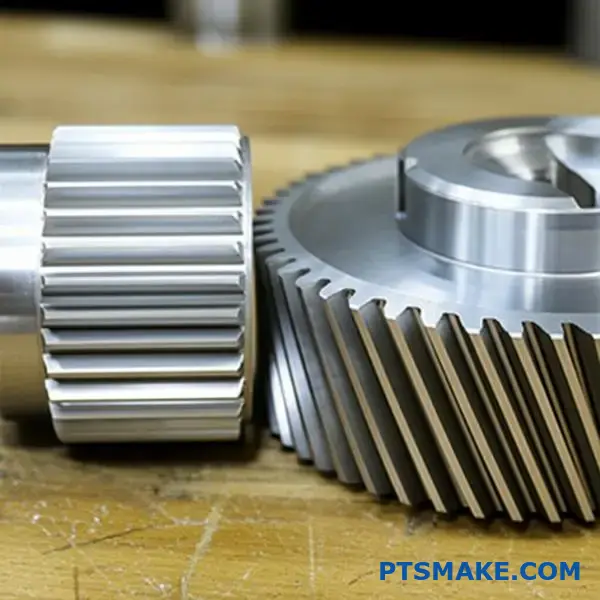
The Mechanics Behind Higher Capacity
The superior load capacity of helical gears stems from two key mechanical advantages. It’s a concept we frequently explain to clients at PTSMAKE when selecting the right gear for demanding applications.
Gradual Engagement and Load Sharing
Unlike the sudden impact of spur gear teeth, helical teeth slide into contact. The load is applied gradually, starting at one end of the tooth and moving across its face.
This means multiple teeth are often in contact simultaneously, sharing the total load. This increased contact ratio significantly reduces the stress on any single tooth. The distribution of Hertzsche Berührungsspannung9 is far more efficient.
Increased Contact Ratio Explained
The contact ratio is a measure of how many teeth are in mesh at any given time. A higher ratio means better load distribution and smoother operation. In our tests, helical gears demonstrate a significantly higher contact ratio.
| Merkmal | Stirnrad | Stirnradgetriebe |
|---|---|---|
| Zahn Engagement | Abrupt, all at once | Allmählich, progressiv |
| Lastverteilung | Concentrated on one tooth pair | Shared across multiple teeth |
| Typisches Übersetzungsverhältnis | 1.1 to 1.7 | 2.0 or higher |
| Resulting Stress | High peak stress | Lower, distributed stress |
This distribution allows helical gears to handle greater torque and power without increasing the risk of failure from bending fatigue or surface pitting.
Helical gears outperform spur gears in load-carrying capacity due to their angled teeth. This design ensures a higher contact ratio and gradual load application, distributing stress across multiple teeth and resulting in smoother, more robust power transmission under identical conditions.
Wie sehen die Herstellungskosten und die Komplexität aus?
When comparing spur gears vs helical gears, manufacturing is the biggest cost driver. The difference comes down to geometry.
The Simplicity of Spur Gears
Spur gears have straight teeth. This simple design makes them much easier to produce. We can use standard processes like hobbing or shaping.
The entire tooth can be cut in a single pass. This leads to faster cycle times and lower costs.
The Complexity of Helical Gears
Helical gears have angled teeth. This angle introduces complexity. Manufacturing requires more precise machine setups and specialized tooling to create the helix.
| Getriebetyp | Manufacturing Ease | Typischer Prozess |
|---|---|---|
| Stirnrad | Hoch | Hobbing, Shaping |
| Stirnradgetriebe | Mäßig | Specialized Hobbing |
This complexity directly translates to longer machining times and higher production costs.
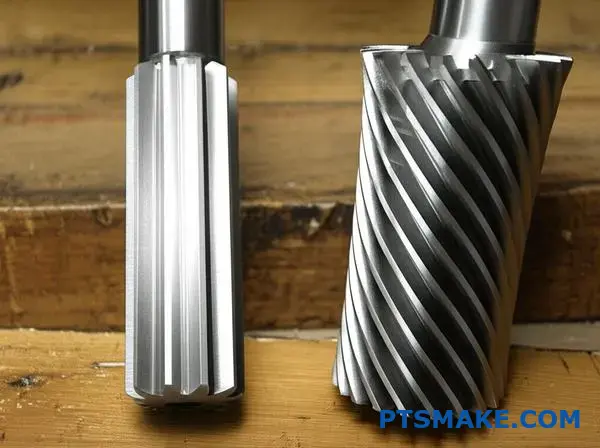
The manufacturing process itself tells the story of cost. For many of our clients at PTSMAKE, understanding this is key to budgeting their projects effectively.
Deeper Dive into Machining Methods
Spur Gear Machining
Manufacturing spur gears is a very direct process. We often use a hobbing machine. The cutting tool, or hob, and the gear blank rotate together. The hob cuts the straight teeth efficiently.
This process is highly automated and fast. It requires less complex setups, minimizing labor and machine time. This is a primary reason for their cost-effectiveness.
Helical Gear Machining
Producing helical gears is more involved. The machine must cut teeth at a specific helix angle. This requires a synchronized, helical motion between the hob and the gear blank.
This process also creates significant Axialschub10, requiring robust machine setups to maintain precision. The setup is more time-consuming, and cutting speeds are often slower to ensure accuracy.
| Merkmal | Spur Gear Machining | Helical Gear Machining |
|---|---|---|
| Werkzeugpfad | Gerade, parallel zur Achse | Angled, helical path |
| Einrichten der Maschine | Simpler, faster | More complex, requires angle sync |
| Zykluszeit | Kürzere | Länger |
| Werkzeugbau | Standard hob | Angle-specific hob |
| Associated Forces | Primarily radial forces | Radial and axial forces |
Each step adds time and requires greater operator skill, increasing the final cost per part.
Spur gears are cheaper and faster to produce due to their simple, straight-tooth geometry. Helical gears, with their angled teeth, demand more complex machining setups, specialized tooling, and longer cycle times, which drives up manufacturing costs.
Welche Lagerungsarten sind für die einzelnen Getriebetypen erforderlich?
Choosing the right bearing is crucial. It directly impacts the gear system’s performance and lifespan. The primary difference comes down to the forces each gear type generates.
Spur Gear Bearing Needs
Spur gears have straight teeth. Because of this, they mainly produce radial loads. This simplifies bearing selection. Bearings only need to support the shaft against these outward forces.
Helical Gear Bearing Needs
Helical gears, with their angled teeth, are more complex. They generate both radial and significant axial loads. This requires a more robust bearing arrangement to handle forces from multiple directions.
A quick comparison of Stirnradgetriebe im Vergleich zu Schrägstirnrädern loads is below.
| Getriebetyp | Primärlast | Secondary Load |
|---|---|---|
| Stirnrad | Radial | Minimal |
| Stirnradgetriebe | Radial | Axial (Schubkraft) |
Deeper Dive into Bearing Selection
The load characteristics of each gear type dictate the bearing arrangement. It’s a fundamental concept we always emphasize in our design consultations at PTSMAKE. Getting this wrong leads to premature failure.
Bearings for Spur Gears
For spur gears, the focus is on managing radial forces. Simple bearing types often work well.
Deep groove ball bearings are a common choice. They are cost-effective and handle radial loads efficiently. In some higher-load applications, cylindrical roller bearings might be used for greater radial capacity.
Bearings for Helical Gears
Helical gears are different. The helix angle of the teeth creates a continuous pushing force along the shaft’s axis. This force is known as Axialschub11.
This combined load profile requires more advanced solutions. A single deep groove ball bearing is usually not enough.
We often recommend tapered roller bearings. They are designed to handle heavy radial and axial loads simultaneously. Arranging them in pairs (back-to-back or face-to-face) is a standard practice to counteract thrust in both directions.
Here is a guide for bearing selection.
| Getriebetyp | Common Bearing Type | Grund |
|---|---|---|
| Stirnrad | Deep Groove Ball Bearing | Excellent for radial loads, cost-effective. |
| Stirnradgetriebe | Tapered Roller Bearing | Handles combined radial and high axial loads. |
In short, spur gears require bearings for radial loads. Helical gears need robust systems, like tapered roller bearings, to manage both significant radial and axial forces. Proper selection is key to the gearbox’s reliability and long-term performance.
Bei welchen Anwendungen sind Stirnradgetriebe die beste Wahl?
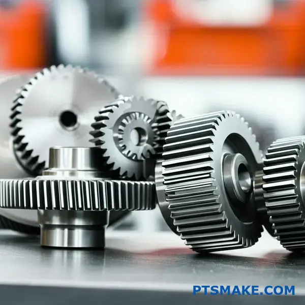
Spur gears shine where simplicity and cost are key. They are the workhorses for straightforward power transmission between parallel shafts.
Their design eliminates axial thrust, which simplifies bearing requirements and housing design. This makes them ideal for many machines.
Key Selection Criteria
Kosten-Wirksamkeit
Spur gears are generally less expensive to manufacture than helical gears. This is a major factor in high-volume production.
Simplicity in Design
Their simple geometry makes them easy to design and install. At PTSMAKE, we can machine them to precise tolerances efficiently.
| Merkmal | Stirnräder | Schraubenförmige Zahnräder |
|---|---|---|
| Kosten | Unter | Höher |
| Axialschub | Keine | Gegenwart |
| Wellenausrichtung | Parallel Only | Parallel & Perpendicular |
| Lärmpegel | Höher | Unter |
Application Deep Dive
The choice in the spur gears vs helical gears debate often comes down to the specific application’s demands. Spur gears are not just a budget option; they are the technically superior choice in certain scenarios. Their direct, efficient power transfer is unbeatable for simple systems.
Simple Transmissions
Think of washing machines or blenders. These devices need reliable torque transfer without the complexity or cost of more advanced gear systems. Spur gears provide this perfectly. They get the job done efficiently and keep the final product affordable for consumers.
Positive Displacement Pumps
In our experience with clients in the fluid power industry, precision is non-negotiable. Pumps that use meshing spur gears, known as gear pumps, rely on the constant volume transfer created by the gear teeth. The design ensures a consistent, non-pulsating flow, critical for hydraulic systems. The gears must be precise, a service we specialize in at PTSMAKE through CNC machining. This is a classic case where the simple geometry of a spur gear outperforms a complex one.
Fördersysteme
Conveyor belts in factories or warehouses need consistent, reliable motion. They operate at moderate speeds where noise is less of a concern. Spur gears provide the needed torque to drive the belts without the added cost and complexity of dealing with axial loads. Their durability ensures long service life with minimal maintenance. This is crucial for keeping production lines running smoothly.
| Anmeldung | Primary Reason for Spur Gear Choice |
|---|---|
| Washing Machine | Low Cost, Simplicity |
| Gear Pumps | Präzise Positive Displacement12, No Axial Thrust |
| Fördergurte | Reliability, Cost-Effectiveness |
| Elektrische Werkzeuge | High Torque Transfer, Simple Assembly |
Spur gears are the superior choice for applications where simplicity, cost-effectiveness, and the absence of axial thrust are critical. They excel in straightforward power transmission systems like simple transmissions, pumps, and conveyors, offering reliability and easy maintenance.
Für welche Anwendungen sind schrägverzahnte Zahnräder die erste Wahl?
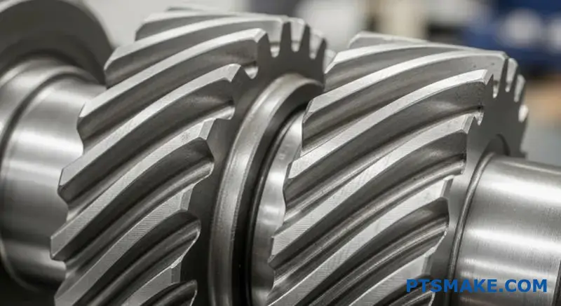
When performance cannot be compromised, helical gears are the only choice. Their design is perfect for applications needing smooth, quiet power transmission. Think about high-speed, high-load environments.
Spur gears simply can’t compete here. The gradual engagement of helical teeth reduces noise and vibration. This makes them essential in specific industries.
Leistungsstarke Anwendungen
Kfz-Getriebe
In cars, especially electric vehicles, noise reduction is critical. Helical gears ensure a quiet and smooth ride for passengers.
Industrial Gearboxes
For heavy machinery and turbines, reliability is key. Helical gears handle higher loads and speeds, ensuring long-term operational stability.
| Anmeldung | Schlüsselanforderung | Why Helical Gears? |
|---|---|---|
| Automobilindustrie | Geräuscharmer Betrieb | Angled teeth reduce noise and vibration. |
| Turbines | High-Speed Power | Smooth engagement handles high RPMs. |
| Industriell | High-Load Capacity | Greater tooth contact distributes stress. |
In the debate of spur gears vs helical gears, the application dictates the winner. While spur gears are efficient and simpler to make, they are noisy at high speeds. This is due to the abrupt contact between teeth.
Helical gears solve this problem. The angled teeth engage gradually across the face of the gear. This creates a much smoother and quieter transfer of power. Our testing at PTSMAKE consistently shows a significant reduction in noise, vibration, and harshness (NVH).
The Engineering Trade-Off
This smooth operation comes with a trade-off. The angled teeth produce Axialschub13, a force that pushes the gears apart along their shafts. This force must be managed with appropriate bearings, like thrust bearings.
This adds some complexity and cost to the design. However, for applications where performance is paramount, it is a necessary engineering decision. Ignoring it can lead to premature failure.
Anwendungsspezifische Vorteile
| Merkmal | Automotive Benefit | Industrieller Nutzen |
|---|---|---|
| Reibungsloses Engagement | Enhanced driving comfort. | Reduced wear on machinery. |
| High-Speed-Fähigkeit | Suitable for modern engines and EVs. | Essential for power generation turbines. |
| Greater Load Capacity | Increased transmission reliability. | Longer lifespan for heavy-duty gearboxes. |
At PTSMAKE, we guide clients through these trade-offs. We help them select the right gear type and design the supporting systems to ensure optimal performance and durability for their specific application.
For high-speed, high-power systems like automotive transmissions and industrial turbines, helical gears are mandatory. Their design ensures smooth, quiet operation, despite the added complexity of managing axial thrust. Spur gears are simply too noisy for these demanding applications.
Wie unterscheidet sich die Schmierungsstrategie für gerad- und schrägverzahnte Zahnräder?
While all gears need lubrication, the choice of lubricant is not one-size-fits-all. The strategy differs significantly when comparing spur gears vs helical gears.
Spur gears often work well with general-purpose lubricants. Their straight-tooth design results primarily in rolling contact. This means less friction and heat buildup.
Helical gears, however, introduce more sliding motion. This is due to their angled teeth. This sliding action can create higher pressures and temperatures at the contact points.
Key Lubricant Factors
| Getriebetyp | Primärer Kontakt | Lubricant Requirement |
|---|---|---|
| Stirnrad | Rollender | General Purpose, Lower Viscosity |
| Stirnradgetriebe | Sliding & Rolling | Higher Viscosity, EP Additives |
This distinction is critical for long-term performance.
The Role of Extreme Pressure Additives
The sliding action in helical gears is the main reason for different lubrication needs. This sliding under load creates a challenge that standard lubricants can’t always handle. It generates significant frictional heat.
This heat can break down the oil film between the teeth. When this film fails, you get metal-to-metal contact, leading to scuffing and premature wear. This is a common failure mode we’ve seen in high-load applications.
To prevent this, lubricants for helical gears often need special additives. This is where lubricants with specific Zusatzstoffe für extremen Druck (EP)14 become non-negotiable.
When are EP Additives Necessary?
Based on our tests with clients, the need for EP additives becomes clear under specific conditions.
| Betriebsbedingung | Spur Gear Lubricant | Helical Gear Lubricant |
|---|---|---|
| Low Speed, Low Load | Standard Gear Oil | Standard Gear Oil |
| High Speed, High Load | Standard Gear Oil | Oil with EP Additives |
| Schockbelastung | May need mild EP | Requires robust EP Additives |
These additives form a protective chemical layer on the gear surface. This layer acts as a last line of defense when the oil film is compromised. It prevents the gear teeth from welding together under intense pressure. At PTSMAKE, we always review the operational loads to recommend the right lubricant strategy.
While both gear types require lubrication, the higher sliding forces in helical gears often necessitate lubricants with EP additives. This choice is crucial for preventing wear and ensuring the drivetrain’s reliability, especially under heavy loads.
Wie empfindlich ist die Ausrichtung der Gänge im Vergleich zwischen den beiden?
Gear alignment is critical for performance and lifespan. Even slight misalignment can cause major problems.
Helical gears are generally more sensitive to this. Their angled teeth require precise positioning.
Without it, the load doesn’t spread evenly. This leads to noise, vibration, and premature failure. Let’s explore why this happens.
| Getriebetyp | Ausrichtungsempfindlichkeit | Hauptgrund |
|---|---|---|
| Stirnräder | Less Sensitive (to parallel) | Full-line contact along the tooth face. |
| Schraubenförmige Zahnräder | More Sensitive | Angled contact requires perfect shaft parallelism. |
The Critical Nature of Shaft Alignment
In any gear system, perfect shaft alignment is the goal. However, in reality, small deviations always exist. How each gear type handles this imperfection is a key factor in the spur gears vs helical gears debate.
Helical Gear Sensitivity Explained
Helical gears achieve their smooth, quiet operation through gradual tooth engagement. The contact starts at one end of the tooth and moves across its face.
This gradual contact is a strength but also a weakness. If shafts are misaligned, the load concentrates on one part of the tooth. This creates localized pressure points, or Spannungskonzentration15, leading to accelerated wear and pitting.
In our work at PTSMAKE, we’ve seen helical gear sets fail early due to minor assembly errors. The resulting uneven wear pattern is a clear sign of alignment issues.
| Versatz Typ | Impact on Helical Gears | Impact on Spur Gears |
|---|---|---|
| Parallel | High. Causes load to concentrate at tooth ends. | Moderate. Still maintains line contact, but unevenly. |
| Eckig | Very High. Drastically alters contact pattern and load. | High. Leads to edge loading and high stress. |
Spur Gear Forgiveness
Spur gears, with their straight teeth, are more forgiving of slight parallel shaft misalignment. The load is distributed across the entire tooth face.
While not immune, they can tolerate minor imperfections better without immediate catastrophic failure. However, angular misalignment is still very damaging.
In summary, helical gears demand higher precision in assembly. Their design, which provides smooth operation, also makes them more sensitive to misalignment. Spur gears offer more tolerance, particularly for parallel shaft deviations, making them more robust in some applications.
Wie begrenzt die Betriebsgeschwindigkeit ihre jeweiligen Anwendungen?
Operating speed is a critical factor when choosing between spur and helical gears. It directly influences noise, vibration, and the dynamic loads within a system.
For spur gears, there is a practical speed limit. Their straight-tooth design causes an abrupt, full-line contact during meshing. This creates impact forces that escalate with speed.
This is a key consideration in the spur gears vs helical gears debate. Below is a quick comparison of their speed-related characteristics.
| Merkmal | Stirnräder | Schraubenförmige Zahnräder |
|---|---|---|
| Speed Suitability | Gering bis mäßig | Hoch |
| Noise at Speed | Hoch | Niedrig |
| Impact on Meshing | Bedeutend | Minimal |
This abrupt engagement is why spur gears become noisy and vibrate at higher speeds.
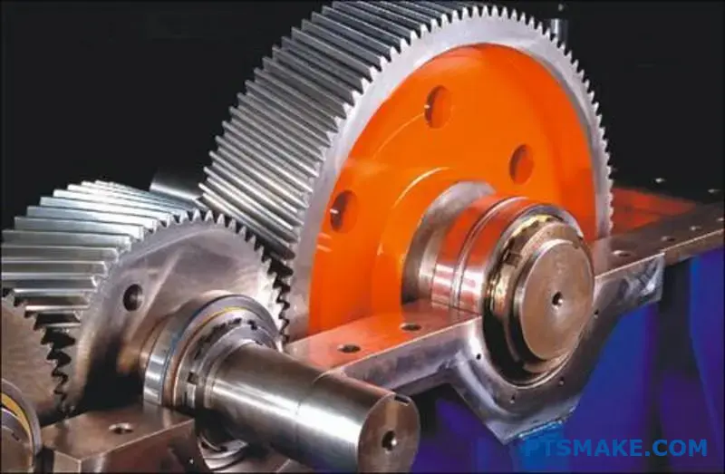
The Challenge of Speed with Spur Gears
The core issue with spur gears at high speeds is their geometry. The entire face of the tooth engages at once. Think of it as a small, rapid hammering effect. As the gear spins faster, these impacts become more frequent and forceful.
This generates significant dynamic loads16, stressing the gear teeth and creating audible noise. Past a certain rotational speed, this vibration can compromise the entire system’s reliability and performance. This effectively creates a practical speed limit for their use.
Why Helical Gears Excel at High Speeds
Helical gears overcome this limitation elegantly. Their angled teeth ensure that contact begins at one end of the tooth and progresses smoothly across its face. This gradual engagement eliminates the impact forces characteristic of spur gears.
This smooth meshing allows for quieter operation and significantly less vibration. In the projects we handle at PTSMAKE, this quality makes helical gears the default choice for applications requiring high rotational speeds, like in automotive transmissions or precision industrial machinery.
| Geschwindigkeitsbereich | Preferred Gear Type | Key Justification |
|---|---|---|
| Gering bis mäßig | Stirnrad | Simplicity and cost-efficiency. |
| Hoch | Stirnradgetriebe | Smooth, quiet operation and reliability. |
This fundamental difference in engagement is what sets their application ranges apart.
Spur gears are limited by speed due to the impact forces and noise from their abrupt tooth engagement. Helical gears, with their gradual meshing, operate smoothly and quietly, making them essential for high-speed applications where reliability and low noise are critical.
Wie wählt man den richtigen Getriebetyp für eine Anwendung aus?
Choosing the right gear involves a structured process. It’s not just about a single specification. You must balance several key factors.
This ensures the final choice meets all performance goals. I always start with the primary application requirements.
Key Decision-Making Factors
A clear framework prevents costly errors. Consider these five critical areas before making a decision. Each one impacts the gear’s suitability.
| Faktor | Beschreibung |
|---|---|
| Drehzahl (RPM) | The operational rotational speed required. |
| Drehmoment | The rotational force the gear must transmit. |
| Lärmpegel | The acceptable level of sound during operation. |
| Budget | The cost constraints for the component. |
| Platzbeschränkungen | The physical space available for the gear system. |
A Step-by-Step Selection Framework
At PTSMAKE, we guide our partners through a systematic process. It starts with defining primary requirements. This ensures the correct gear is selected for both performance and manufacturability.
A common starting point is the choice of spur gears vs helical gears. Spur gears are efficient and cost-effective for moderate speeds. Helical gears run smoother and quieter, making them ideal for high-speed or noise-sensitive applications.
However, the decision is rarely that simple. You must consider how different gear types perform across all criteria. Precision applications also introduce factors like Rückwirkung17, which can be critical.
Decision Matrix for Gear Selection
We often use a decision matrix with clients. This tool helps visualize the trade-offs between different gear types. It provides a clear, data-driven path to the best solution.
| Getriebetyp | Bewertung der Geschwindigkeit | Drehmoment Kapazität | Lärmpegel | Relative Kosten | Wirkungsgrad |
|---|---|---|---|---|---|
| Spur | Mittel | Mittel | Hoch | Niedrig | Sehr hoch |
| Wendel | Hoch | Hoch | Niedrig | Mittel | Hoch |
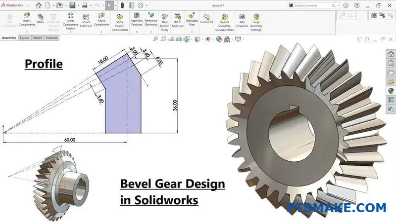
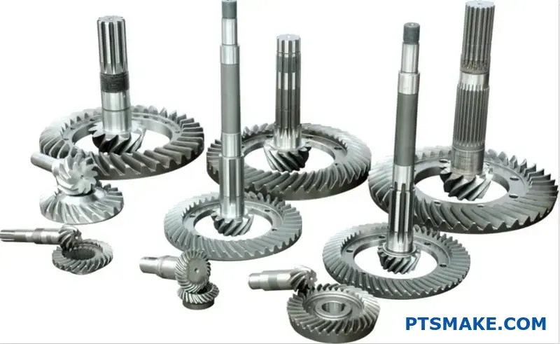
| Fase | Mittel | Mittel | Mittel | Hoch | Hoch |
| Wurm | Niedrig | Sehr hoch | Sehr niedrig | Mittel | Niedrig bis mittel |
This matrix is a starting point. Your specific application will determine the right balance.
A structured decision framework simplifies gear selection. By evaluating requirements like speed, torque, noise, budget, and space, you can systematically identify the optimal gear type for your specific needs, avoiding guesswork and ensuring reliable performance.
Wie wählt man das richtige Material für ein Zahnrad aus?
Choosing the right gear material is a critical decision. It directly impacts the performance, lifespan, and overall cost of your product. Your application’s specific demands must guide your selection.
Think about factors like load, speed, and the operational environment. A high-torque steel gear for an automotive transmission has very different needs than a low-noise plastic gear inside an office printer.
Here is a quick overview to get started:
| Material-Kategorie | Hauptvorteil | Allgemeiner Anwendungsfall |
|---|---|---|
| Stahl-Legierungen | Hohe Festigkeit und Langlebigkeit | Kfz-Getriebe |
| Kunststoffe | Low Noise & Corrosion Resistance | Office Equipment, Medical |
| Bronze-Legierungen | Geringe Reibung und Anpassungsfähigkeit | Schneckenradantriebe |
This guide will help you navigate these options for your project.
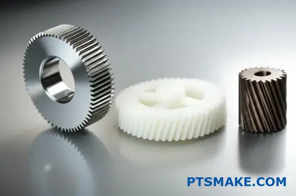
Let’s dive deeper into a practical material selection guide. The best choice always balances performance with budget. At PTSMAKE, we often start by analyzing the operational forces and environment to find this balance.
Steel Alloys for High-Stress Jobs
For high strength and durability, steel is the go-to material. It handles high loads and wear exceptionally well, whether for spur gears or helical gears. Heat treatment can also significantly enhance its properties.
| Steel Alloy | Am besten für | Hauptmerkmal |
|---|---|---|
| 4140 Stahl | High Torque & Toughness | Fähigkeit zur Durchhärtung |
| 8620 Steel | Impact & Surface Wear | Excellent for case hardening |
Plastics for Specialized Applications
Do not underestimate plastics. They solve common issues like noise, corrosion, and the need for external lubrication. Based on our testing, they are ideal for lighter-load applications where these factors are critical.
The unique tribologische Eigenschaften18 of plastics make them essential in many modern designs.
Popular Plastic Options
- Delrin (Acetal): Known for its low friction and excellent dimensional stability. We recommend it for precision moving parts.
- Nylon: Offers good toughness and chemical resistance. It is also fantastic at damping noise and vibration.
Bronze for Low-Friction Mating
Bronze alloys are a classic choice for certain gear types. They are especially common for worm wheels that mate with steel worms. This material pairing offers very low friction and prevents galling under heavy loads.
Choosing the right gear material is a trade-off. Steel provides strength for high loads. Plastics offer quiet, corrosion-resistant operation for lighter duties. Bronze excels in specific low-friction applications. The key is matching the material to your application’s unique demands.
Wie würden Sie ein lautes Stirnradgetriebe so umgestalten, dass es leiser wird?
A noisy spur gear drive is a common engineering challenge. The most effective solution often involves a complete redesign. Simply swapping parts is not enough.
We replace the noisy spur gears with helical gears. This change significantly reduces noise. However, it requires a careful redesign of the entire system.
The key is understanding the differences between spur gears vs helical gears. The angled teeth of helical gears engage gradually, which is why they run quieter.
| Getriebetyp | Verlobung | Lärmpegel |
|---|---|---|
| Stirnrad | Abrupt | Hoch |
| Stirnradgetriebe | Schrittweise | Niedrig |
This redesign involves geometry, bearings, and housing modifications.
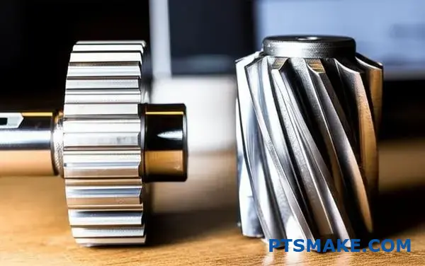
When we redesign a drive for quietness, we go beyond a simple gear swap. The transition from spur to helical gears is a fundamental engineering change. It impacts the entire mechanical assembly.
Recalculating Gear Geometry
The first step is recalculating the gear geometry. The introduction of a helix angle changes everything. It creates a smoother, more gradual tooth engagement. This is the primary reason for the noise reduction. We must adjust the pressure angle and tooth profile to optimize contact and minimize wear.
Specifying New Bearings
Spur gears primarily generate radial loads. Helical gears, due to their angled teeth, produce both radial and Axialer Schub19. This new force must be managed. Standard ball bearings may fail. We must specify bearings capable of handling thrust loads, such as tapered roller bearings or angular contact bearings.
Modifying the Housing
The new bearings and thrust forces require housing modifications. The housing must be rigid enough to support the new bearing arrangement. It must prevent any shaft deflection under load. At PTSMAKE, we often redesign the housing to ensure precise alignment and long-term reliability.
| Design-Aspekt | Spur Gear Drive | Helical Gear Redesign |
|---|---|---|
| Primärlast | Radial | Radial & Axial |
| Lager Typ | Simple Ball Bearing | Tapered/Angular Contact |
| Gehäuse | Standard Rigidity | Reinforced for Thrust |
| Lärm | Hoch | Niedrig |
Switching to helical gears for quiet operation is not just a replacement. It’s a comprehensive redesign involving new geometry, specialized bearings to handle thrust, and a modified housing. This ensures a truly quiet and reliable system.
Wie kann man ein Getriebe so optimieren, dass es möglichst wenig wiegt?
For critical applications like aerospace, every gram matters. Advanced strategies are essential. We move beyond basic design to achieve minimum weight.
High-Performance Materials
Choosing materials like high-strength steel alloys or titanium is the first step. These offer superior strength-to-weight ratios.
Advanced Heat Treatments
Processes like nitriding or carburizing harden the gear surface. This increases load capacity. It allows for a smaller, lighter gear to do the same job.
Gear Blank Optimization
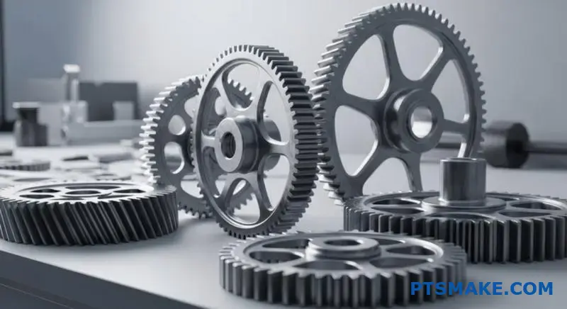
Webbing out the gear blank is a key technique. We strategically remove material from the gear’s body. This reduces weight without affecting the critical tooth area.
| Strategie | Impact on Weight | Betrachtung |
|---|---|---|
| Fortschrittliche Materialien | Hoch | Higher Material Cost |
| Wärmebehandlung | Mittel | Additional Process Step |
| Webbing | Hoch | Complex Machining |
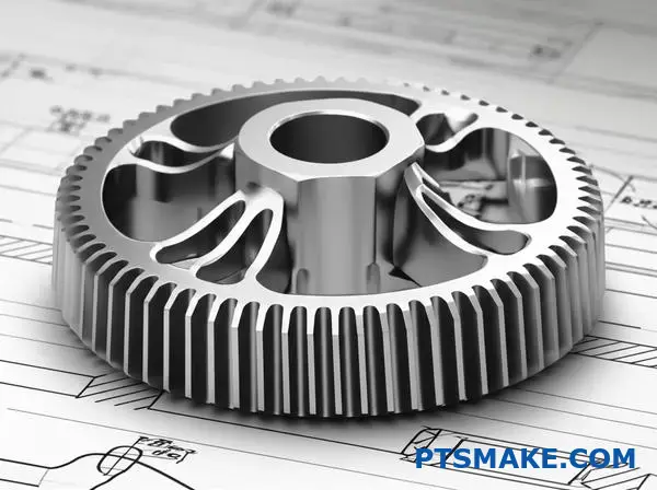
Advanced weight optimization requires a holistic approach. It’s about combining material science, heat treatment, and intelligent geometric design to create a gear that is both strong and incredibly light.
Optimizing the Gear’s Core Structure
Webbing out a gear blank is more art than science. It involves machining pockets of material from the gear’s central disk. This removes non-essential mass. The goal is to create a spoke-like or webbed structure. This maintains rigidity while drastically cutting weight. In past projects at PTSMAKE, we’ve achieved significant weight reduction this way.
| Getriebetyp | Relatives Gewicht | Komplexität |
|---|---|---|
| Solid Blank | 100% | Niedrig |
| Webbed Blank | 60-75% | Hoch |
Tooth Profile and Strength
Beyond the blank, tooth profile modifications are crucial. A subtle adjustment like adding crowning20 can ensure the load is distributed evenly across the tooth face, even under slight misalignment. This prevents stress concentrations at the tooth ends.
This improved load distribution means the gear can handle more stress. Therefore, we can design it to be smaller and lighter from the start. This principle is a key consideration in the debate of spur gears vs helical gears, as each type responds differently to such modifications. Pairing these design tweaks with superior materials and heat treatments is how we deliver top-tier, lightweight gears for demanding industries.
Optimizing for minimum weight involves using high-strength materials and advanced heat treatments. Smart design, such as webbing out the gear blank and modifying the tooth profile, removes non-essential mass without compromising the gear’s structural integrity or performance.
Wann würden Sie sich bewusst für ein Kunststoffstirnrad gegenüber Stahl entscheiden?
It’s easy to think steel is always better. It’s stronger, right? But strength isn’t the only factor. For many applications, a plastic spur gear is the smarter, more efficient choice.
This is especially true when priorities shift. Think about low noise, self-lubrication, or corrosion resistance. In these cases, plastic often outperforms metal. Cost is also a major driver.
| Merkmal | Plastic Gear Advantage | Steel Gear Advantage |
|---|---|---|
| Lärm | Sehr niedrig | Can be high |
| Schmierung | Selbstschmierend | Requires external lubricant |
| Kosten | Lower, especially in high volumes | Higher material & machining cost |
| Gewicht | Leichtgewicht | Schwer |
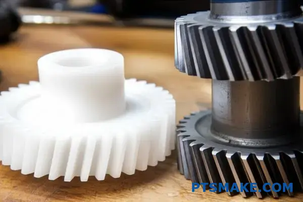
Beyond Brute Strength: Application-Specific Choices
In our work at PTSMAKE, we guide clients on material selection. It’s about matching the material to the real-world environment. Pure strength is often overkill.
Office and Consumer Electronics
Consider a printer or a scanner. These devices sit in offices or homes. They need to run quietly. Steel gears would create too much noise.
Plastic spur gears are perfect here. They operate almost silently. They also don’t need grease, which could stain paper or damage electronics. Their excellent tribologische Eigenschaften21 ensure long life without maintenance.
Environments with Corrosion Risk
What about a device used near water or chemicals? Steel gears would rust and fail quickly. Stainless steel is an option, but it’s expensive.
Plastic gears are naturally immune to corrosion. This makes them ideal for food processing equipment, medical devices, or outdoor products. They provide reliable performance where steel cannot. When comparing spur gears vs helical gears for these uses, the material often matters more than the gear type for longevity.
| Anwendungsbereich | Key Benefit of Plastic |
|---|---|
| Office Printers | Low noise, no lubrication needed |
| Medizinische Geräte | Sterilizable, corrosion-resistant |
| Lebensmittelverarbeitung | Chemical resistance, no contamination |
| Toys & Gadgets | Low cost, lightweight, safe |
In summary, choosing plastic over steel isn’t about compromise. It’s a strategic decision. It prioritizes cost-effectiveness, low noise, and maintenance-free operation in applications where high torque and extreme strength are not the primary requirements.
Analysieren Sie die Auswirkungen des Austauschs eines Stirnrads durch ein Schrägstirnrad auf den Wirkungsgrad.
It’s a common belief that smoother operation equals higher efficiency. But in the spur gears vs helical gears debate, this isn’t always the case.
While helical gears provide a quieter, more gradual engagement, their angled teeth introduce a unique dynamic. This changes the forces at play.
The Source of Inefficiency
The primary difference comes down to the type of contact between teeth. This is a subtle but critical point for any design engineer.
| Getriebetyp | Primary Contact Motion | Ergebnis |
|---|---|---|
| Stirnrad | Rolling/Sliding | Direct Power Transfer |
| Stirnradgetriebe | Increased Sliding | Smoother, but more friction |
This increased sliding action along the tooth face is the key. It generates slightly more friction and heat compared to a spur gear.
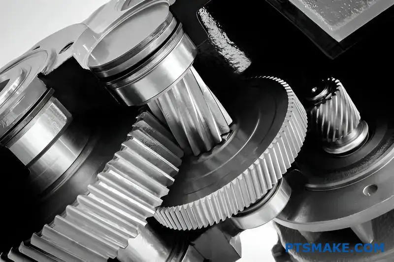
A Deeper Look at Friction and Forces
Let’s break down this trade-off. A spur gear’s teeth mesh with a motion that is largely rolling, with some sliding. This is a very efficient way to transfer power.
Helical gears, due to their helix angle, have teeth that slide into engagement. This continuous sliding contact reduces noise and impact loads, which is a significant advantage.
However, this sliding motion creates more friction than the primarily rolling contact of spur gears. Based on our internal testing, this can result in a minor efficiency loss, typically in the range of 1-3%, depending on the application and lubrication.
Verstehen der Kompromisse
The helical design also creates a force parallel to the gear’s axis. This Axialschub22 must be managed by appropriate bearings, which can introduce their own frictional losses to the system. The choice isn’t always simple.
| Merkmal | Stirnrad | Stirnradgetriebe |
|---|---|---|
| Operation | Lauter | Quieter, Smoother |
| Zahnkontakt | Leitung Kontakt | Schrittweises Engagement |
| Wirkungsgrad | Sehr hoch | Geringfügig niedriger |
| Axial Load | Keine | Ja |
At PTSMAKE, we often work with clients to analyze these subtle points. Choosing the right gear type depends entirely on the specific priorities of the application—be it noise level, load capacity, or maximum efficiency.
Helical gears provide smoother, quieter performance. But their angled teeth increase sliding friction. This creates a slight, but important, efficiency trade-off compared to the more direct rolling action of spur gears.
Mit PTSMAKE erhalten Sie kompetente Lösungen für Stirnrad- und Schrägverzahnungen
Ready for precision gear solutions? Partner with PTSMAKE for custom spur and helical gears—engineered to your exacting standards. Send your RFQ now and experience reliable communication, tight tolerances, fast lead times, and a true commitment to your success.
Understand the crucial role this circle plays in defining the entire involute tooth profile. ↩
Learn how to manage this force for optimal gear system design and longevity. ↩
Learn how this critical geometric feature influences force distribution and gear efficiency. ↩
Explore a deeper dive into how different force vectors combine in gear systems. ↩
See our detailed guide to understand how gear geometry impacts performance. ↩
Understand how this mechanical property influences the vibration and noise levels in gear systems. ↩
Explore how the progressive contact line on helical teeth ensures a smoother, quieter transfer of power. ↩
Understand how this force impacts gear design and what bearings are needed to manage it effectively. ↩
Understand how surface stress analysis can prevent premature gear failure. ↩
Understand how this force influences gear design and the selection of appropriate bearings. ↩
Learn how this force impacts gear design and longevity. ↩
Explore how these pumps use precise gear mechanics to move fluids with exceptional accuracy. ↩
Learn how to calculate and manage this force in your designs. ↩
Discover how these chemical additives prevent catastrophic gear failure under extreme loads. ↩
Learn how stress concentration affects material fatigue and component lifespan. ↩
Understand how these variable forces affect gear longevity and system performance. ↩
Learn more about gear backlash and how to minimize it for high-precision CNC machining applications. ↩
Learn how friction, wear, and lubrication properties determine your gear’s performance and lifespan. ↩
Understand how this force impacts gear design and bearing selection for optimal performance. ↩
Discover how this subtle tooth modification can drastically improve gear meshing and extend operational life. ↩
Learn more about how friction, wear, and lubrication impact gear material performance. ↩
Understand how this force influences bearing choice and system design. ↩


