Du er i gang med at redesigne et transmissionssystem, og tandhjulene skaber et uacceptabelt støjniveau. Projektets tidslinje er stram, dit budget er begrænset, og et skift til spiralformede gear betyder, at du skal redesigne hele lejesystemet og huset.
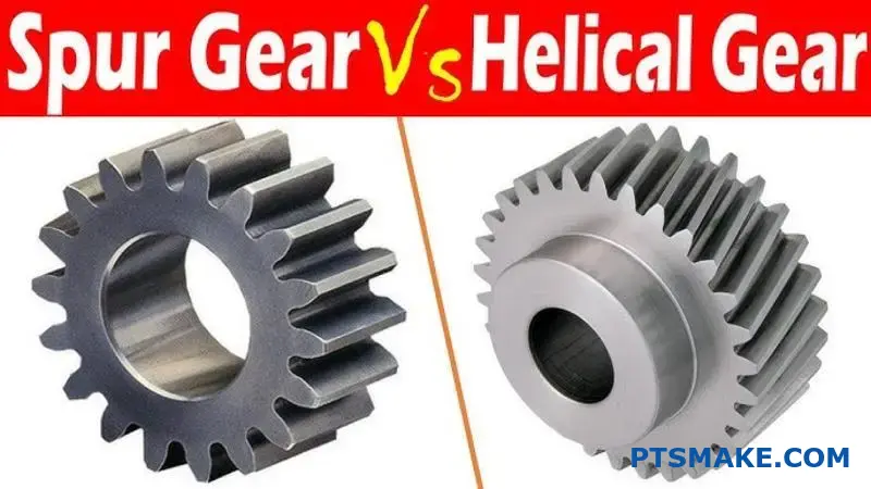
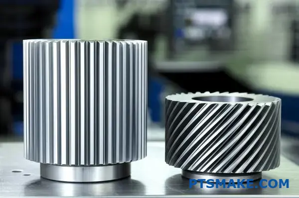
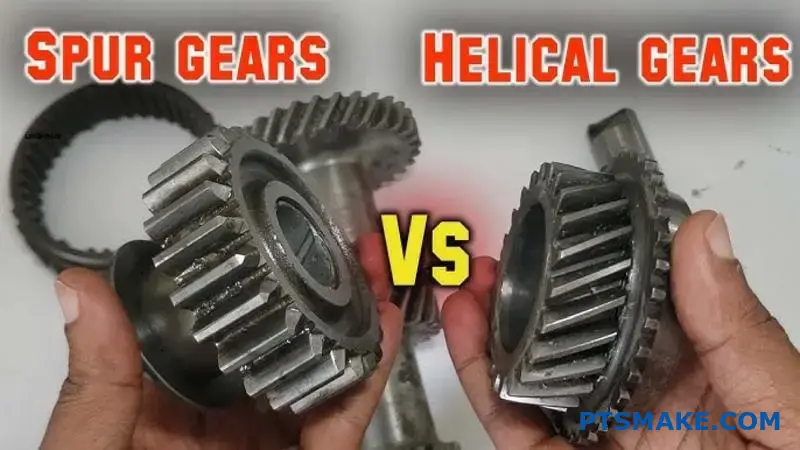
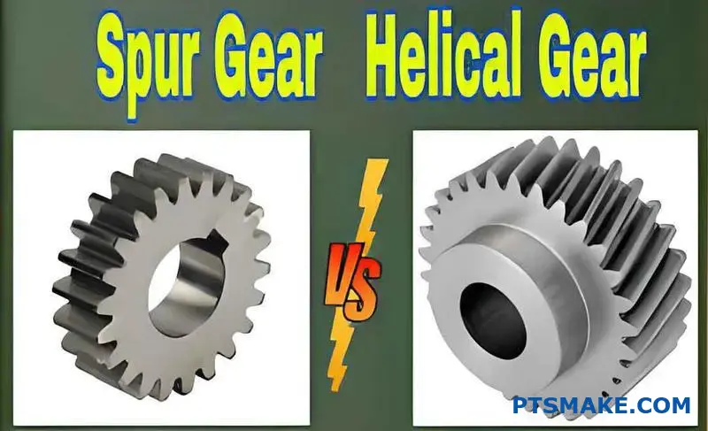
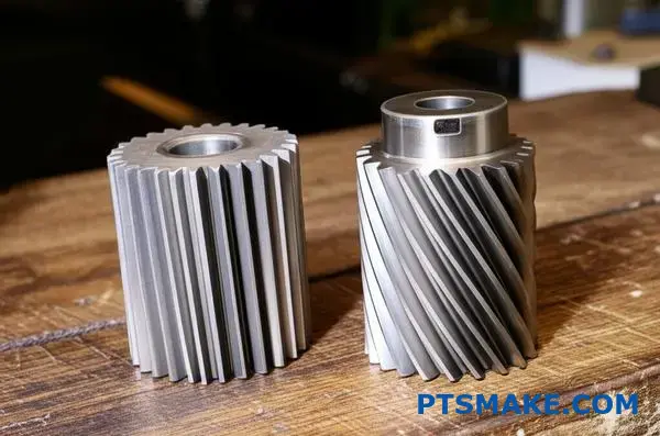
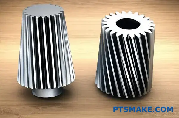
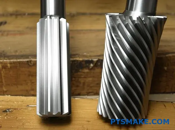
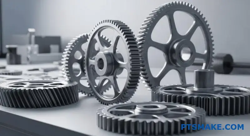
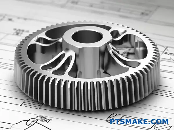
Tandhjulsgear har lige tænder parallelt med akselaksen, mens tandhjulsgear har vinklede tænder, der skaber en spiral omkring gearets omkreds. Denne grundlæggende forskel påvirker alt fra støjniveauer og belastningskapacitet til produktionsomkostninger og krav til lejer.
Gennem mit arbejde hos PTSMAKE har jeg hjulpet ingeniører med at navigere i netop denne beslutning dusinvis af gange. Hver geartype har specifikke styrker, der gør den ideel til bestemte anvendelser. Denne guide gennemgår de tekniske forskelle, afvejninger af ydeevne og udvælgelseskriterier for at hjælpe dig med at træffe det rigtige valg til dit projekt.
Hvad er den grundlæggende geometri, der definerer en tandhjulstand?
Hemmeligheden bag et tandhjuls ydeevne er ikke bare dets form, men en meget specifik kurve. Denne kurve er grundlaget for dets design.
Den ufrivillige profil
Tandprofilen i et moderne tandhjul er i bund og grund en indviklet kurve. Tænk på det som at vikle en snor ud af en cylinder.
Denne specifikke geometri er afgørende. Den sikrer, at rotationshastigheden forbliver helt konstant, når tandhjulene griber ind i hinanden. Det forhindrer rystelser og ujævn kraftoverførsel.
| Geometri-funktion | Formål |
|---|---|
| Involveret kurve | Konstant hastighedsforhold |
| Lige tand | Aksial kraftoverførsel |
| Korrekt afstand | Glat engagement |
Hvordan Involute sikrer problemfri drift
Den indviklede form er ikke vilkårlig. Det er en præcis matematisk profil, der er designet af én primær grund: at opretholde et konstant hastighedsforhold mellem tandhjul, der griber ind i hinanden. Det er et ufravigeligt princip for effektiv kraftoverførsel.
Magien i det almindelige normale
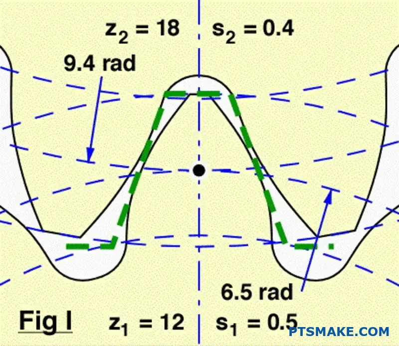
Når to tandhjulstænder kommer i kontakt med hinanden, går den fælles normal (en linje vinkelret på overfladerne ved kontaktpunktet) altid gennem et fast punkt. Dette faste punkt kaldes pitch-punktet.
Denne ensartede geometri sikrer, at det drivende gear skubber det drevne gear med en konstant hastighed. Der er ingen accelerationer eller decelerationer under indgrebet. Dette er en vigtig forskel, når man sammenligner Tandhjul vs. spiralformede tandhjul, da begge er afhængige af dette princip for at fungere problemfrit.
Den indviklede kurve genereres ud fra en Basiscirkel1. Størrelsen på denne cirkel er afgørende for den endelige tandform og dens egenskaber. I vores arbejde hos PTSMAKE er den rigtige geometri afgørende for de højpræcisionsdele, som vores kunder er afhængige af.
| Design-aspekt | Konsekvens af ufleksibel geometri |
|---|---|
| Kontaktpunkt | Bevæger sig langs tandfladen |
| Handlingslinje | Forbliver konstant og tangerer begge grundcirkler |
| Hastighedsforhold | Forbliver konstant gennem hele masken |
Den indviklede kurve er den grundlæggende geometri for en tandhjulstand. Denne specifikke profil er afgørende for at opnå et konstant hastighedsforhold, som garanterer en jævn, pålidelig og effektiv kraftoverførsel mellem tandhjulene.
Hvordan ændrer en spiralvinkel fundamentalt et gears karakter?
Helixvinklen er den vigtigste funktion. Den adskiller et tandhjulsgear fra et cylindrisk gear. Det er ikke bare en visuel finesse.
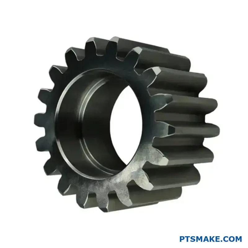
Tandhjul har lige tænder. De griber ind langs hele deres flade på én gang. Det skaber en brat, lineær kontakt.
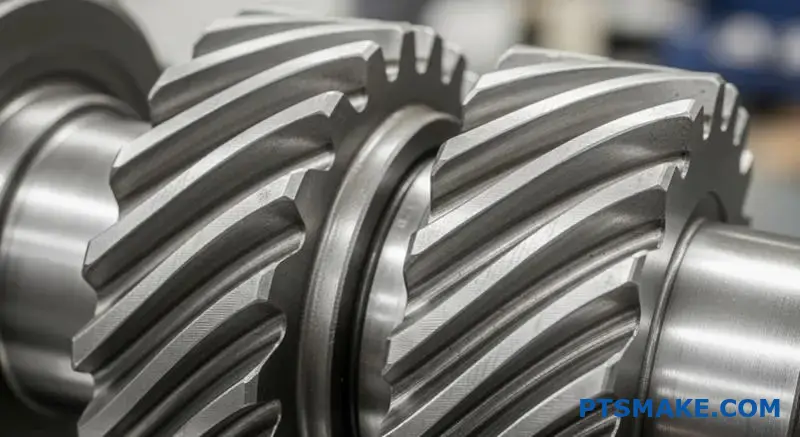
Spiralformede tandhjul med vinklede tænder griber ind på en anden måde. Kontakten starter i den ene ende af tanden. Den bevæger sig derefter jævnt hen over fladen, når gearet roterer.
Dette gradvise engagement er nøglen.
| Funktion | Tandhjul | Spiralformet gear |
|---|---|---|
| Justering af tænder | Lige ud | Vinklet (Helix-vinkel) |
| Første kontakt | Fuld linje | Kontaktpunkt |
| Forlovelsesstil | Pludselig | Gradvis og glat |
Mekanikken bag gradvis engagement
Denne gradvise indgrebsproces ændrer alt. I modsætning til den pludselige påvirkning af tandhjul glider spiralformede tænder på plads. Belastningen påføres gradvist, ikke på én gang. Det reducerer stød og vibrationer betydeligt.
Resultatet er en meget mere støjsvag drift. Det er en af de primære grunde til, at designere vælger tandhjulsgear frem for cylindriske tandhjul. I tidligere projekter hos PTSMAKE har skiftet til tandhjulsgear reduceret driftsstøjen med en mærkbar margin. Det er afgørende for medicinsk udstyr og forbrugerelektronik.
Denne vinklede kontakt skaber dog en bivirkning. Den genererer Aksialt tryk2, en kraft parallelt med gearets akse. Denne kraft findes ikke i tandhjul og skal håndteres. Korrekt valg af lejer er afgørende for at håndtere denne belastning og forhindre for tidlig svigt.
Kernen i debatten om tandhjul og skrueformede tandhjul er denne afvejning.
| Aspektet engagement | Fordel | Ulempe |
|---|---|---|
| Gradvis kontakt | Jævnere og mere støjsvag drift | Skaber aksialt tryk |
| Vinklede tænder | Højere samlet kontaktforhold | Kræver robuste lejer |
| Spredning af last | Øget belastningskapacitet | Mere kompleks produktion |
Et skift i fordelingen af belastningen
Denne gradvise indgriben betyder også, at belastningen fordeles på flere tænder i et givet øjeblik. Det står i kontrast til tandhjul, hvor en eller to tænder bærer hele belastningen. Denne fordeling gør, at tandhjulsgear kan klare større belastninger og har en længere levetid.
Spiralvinklen ændrer grundlæggende gearkontakten fra en abrupt linje til et glat, progressivt område. Dette skift er kilden til fordelene med hensyn til støj og belastningskapacitet, men introducerer også udfordringen med aksialt tryk.
Hvilke kræfter virker på en enkelt tandhjulstand under indgreb?
For virkelig at forstå, hvad der sker, når et tandhjul griber ind, må vi opdele den samlede kraft. Denne kraft virker ikke lige på. Den virker i en vinkel i forhold til tandoverfladen.
Ingeniører forenkler dette ved at opdele kraften i to hovedkomponenter. Det gør analyse og design meget nemmere. Det er de tangentielle og radiale kræfter. De har hver især en meget forskellig effekt på gearsystemet.
Forståelse af kraftkomponenterne
Her er en hurtig gennemgang af disse to kræfter og deres primære roller i et gearsystem.
| Kraftkomponent | Primær funktion | Vigtigste indvirkning |
|---|---|---|
| Tangential kraft | Sender strøm | Skaber drejningsmoment til at drive belastningen |
| Radial kraft | Adskiller tandhjul | Belaster lejer og aksler |
Den "arbejdende" kraft: Den tangentielle komponent
Den tangentielle kraft er den komponent, der udfører alt det nyttige arbejde. Den virker tangentielt til gearets stigningscirkel. Det er den kraft, der rent faktisk overfører drejningsmoment og får det drevne gear til at rotere. Når du har brug for mere drejningsmoment, har du at gøre med en større tangentiel kraft.
Den adskillende kraft: Den radiale komponent
Den radiale kraft udfører på den anden side ikke noget nyttigt arbejde for kraftoverførslen. Dens opgave er at skubbe de to tandhjul fra hinanden ved at virke langs en linje, der forbinder deres centre. Denne adskillende kraft er en kritisk faktor for designet. Den belaster akslerne og de lejer, der bærer dem, direkte.
I tidligere projekter hos PTSMAKE har vi set design mislykkes, fordi lejerne ikke var specificeret til at håndtere de radiale belastninger. Det er en afgørende forskel i debatten om tandhjul og skrueformede tandhjul, da skrueformede tandhjul også medfører en aksial kraft (tryk).
Størrelsen af disse kræfter bestemmes af gearets Trykvinkel3. En større vinkel øger den radiale kraft i forhold til den tangentielle kraft.
Oversigt over kraftretning
| Kraft | Handlingens retning | Konsekvenser |
|---|---|---|
| Tangential | Tangent til tonehøjdecirkel | Transmission af drejningsmoment |
| Radial | På vej mod Gear Center | Bærende belastning |
Den samlede kraft på en tandhjulstand forstås bedst ved hjælp af dens tangentielle og radiale komponenter. Den tangentielle kraft driver maskinen, mens den radiale kraft skaber belastninger på aksler og lejer. Korrekt design tager højde for begge dele.
Hvilken ny kraftkomponent introduceres af spiralformede tandhjul?
Spiralformede gear introducerer en betydelig kraftkomponent, som ikke findes i tandhjul: aksialt tryk. Denne kraft virker parallelt med gearets akse og skubber i bund og grund gearet sidelæns.
Dens oprindelse ligger i tandhjulets vinklede tænder.
En vigtig designforskel
Når spiralformede tænder griber ind i hinanden, skaber kontakten en kraft, der ikke er vinkelret på akslen. Dette skaber den aksiale komponent.
| Geartype | Primære kræfter | Ny styrkekomponent |
|---|---|---|
| Tandhjul | Radial, tangentiel | Ingen |
| Spiralformet gear | Radial, tangentiel | Aksialt tryk |
Denne nye kraft kræver omhyggelig styring i dit design.
Fysikken bag aksial fremdrift
Spiralvinklen er den direkte årsag til aksialt tryk. Når kraften overføres, er kraften på tandoverfladen vinkelret på selve tanden. Fordi tanden er i en vinkel, opløses denne kraft i to nøglekomponenter.
Den ene er den tangentielle kraft, som driver rotationen. Den anden er den aksiale kraft, som skubber langs akslen. Dette er et kernekoncept, når man sammenligner tandhjul med skrueformede tandhjul. Jo større spiralvinklen er, jo større er den aksiale kraft ved et givet drejningsmoment.
Beregning af indvirkningen
Dette tryk er ikke et mindre problem. Det skal imødegås med passende lejer, f.eks. koniske rullelejer eller tryklejer. Hvis man ignorerer det, kan det føre til for tidlig lejesvigt og fejljustering af systemet.
Den samlede belastning på tanden skaber en resulterende kraft4 der er en kombination af disse komponenter. I vores arbejde hos PTSMAKE beregner vi præcist disse belastninger for at sikre, at hver eneste komponent, vi fremstiller, fungerer pålideligt i den endelige samling.
Helix-vinklens direkte effekt
| Helix-vinkel | Relativt aksialt tryk |
|---|---|
| 15° | Lav |
| 30° | Medium |
| 45° | Høj |
Dette forhold er afgørende for ingeniører. Hvis man vælger en højere spiralvinkel for at få en mere jævn drift, skal man til gengæld håndtere større aksiale belastninger.
Spiralformede tandhjul giver et aksialt tryk på grund af deres vinklede tænder. Denne kraft er direkte proportional med det overførte drejningsmoment og tangenten af spiralvinklen. Korrekt lejevalg er afgørende for at håndtere denne belastning, en kritisk overvejelse, der ikke findes i tandhjulssystemer.
Hvordan defineres 'kontaktforhold' for tandhjul og skrueformede tandhjul?
Kontaktforholdet er et vigtigt mål for gear. Det definerer det gennemsnitlige antal tandpar, der er i kontakt på et givet tidspunkt. En højere ratio betyder, at flere tænder deler belastningen.
Det resulterer i en mere jævn kraftoverførsel. Det reducerer også støj og vibrationer betydeligt.
Kontaktforhold mellem sporer og spiraler
Tandhjulets udformning har direkte indflydelse på dette forhold. Lad os sammenligne dem.
| Geartype | Typisk kontaktforhold | Inddragelse af tænder |
|---|---|---|
| Tandhjul | 1,2 til 1,8 | Sekventiel, et par kobler sig på, mens et andet kobler sig fra |
| Spiralformet gear | > 2.0 | Overlappende, flere par i kontakt på samme tid |
Denne forskel er afgørende for deres præstationer.
Forstå mekanikken i kontaktforholdet
Forskellen i kontaktforhold skyldes tandgeometrien. Tandhjulsgear har lige tænder. Det betyder, at kontakten sker langs hele tandfladen på én gang. Indgrebet er pludseligt.
Spiralformede tandhjul har derimod vinklede tænder. Det skaber et gradvist indgreb. Kontakten starter i den ene ende af tanden og bevæger sig hen over dens overflade, når gearet roterer.
Gradvis indgreb i skrueformede tandhjul
Dette vinklede design forlænger Kontaktens vej5. Det gør, at et nyt tandpar kan begynde at gå i indgreb, før det forrige par er gået helt ud af indgreb. Dette overlap er grunden til, at deres kontaktforhold altid er større end 2,0.
Det er vores erfaring hos PTSMAKE, at det er en afgørende faktor. Når kunder diskuterer Tandhjul vs. spiralformede tandhjul Til applikationer, der kræver lav støj, gør det højere kontaktforhold i spiralformede gear dem ofte til det klare valg.
Praktiske konsekvenser
Et højere kontaktforhold fordeler belastningen på flere tænder. Det reducerer belastningen på de enkelte tænder. Det forbedrer bæreevnen og forlænger gearets levetid.
| Funktion | Tandhjul (lavere udveksling) | Spiralformet gear (højere udveksling) |
|---|---|---|
| Fordeling af belastning | Koncentreret om 1-2 tandpar | Spredt over 2+ tandpar |
| Støjniveau | Højere | Lavere |
| Vibrationer | Mere udtalt | Jævnere drift |
| Stress på tænderne | Højere | Lavere |
Det gør tandhjulsgear ideelle til applikationer med høj hastighed og høj effekt, hvor glathed er afgørende.
Kontaktforholdet måler det samtidige tandindgreb. Spiralformede gear har et højere, overlappende forhold sammenlignet med tandhjulsgear. Det giver en mere jævn og støjsvag drift og en bedre belastningsfordeling, hvilket er en afgørende forskel ved valg af gear.
Hvilket fysisk fænomen er den primære kilde til støj fra tandhjul?
Problemets kerne er slag. Den primære kilde til støj fra tandhjul er den pludselige kollision mellem tænderne, når de går i indgreb.
I modsætning til en jævn rulning er dette en pludselig begivenhed. Denne påvirkning skaber en øjeblikkelig trykspids.
Denne trykændring forårsager vibrationer. Disse vibrationer bevæger sig gennem tandhjulsmaterialet og den omgivende luft, hvilket vores ører registrerer som støj.
Processen gentages med hver eneste tand, der griber ind i hinanden, hvilket skaber en karakteristisk hvinen.
| Trin | Fysisk handling | Resultat |
|---|---|---|
| 1. Engagement | Tænderne støder pludseligt sammen | Pludselig påvirkning |
| 2. Påvirkning | Overførsel af energi | Skarp trykstigning |
| 3. Forplantning | Spike stråler udad | Vibration (støj) |
Denne hurtige, gentagne påvirkning er det grundlæggende fysiske fænomen, vi er nødt til at forholde os til.
Mekanismerne bag pludseligt engagement
Lad os grave dybere i denne påvirkning. Tandhjulets tænder mødes i hele deres bredde på samme tid. Denne øjeblikkelige linjekontakt betyder, at der ikke sker nogen gradvis overførsel af belastning. Det er en alt-eller-intet-begivenhed.
Denne stødbelastning er den grundlæggende årsag. Hvert indgreb virker som et lille hammerslag på systemet og skaber en trykbølge.
Fra vibration til hørbar støj
Denne trykbølge stråler væk fra tandhjulene. Når den bevæger sig gennem luften, opfatter vi den som lyd. Frekvensen af denne lyd er direkte knyttet til, hvor ofte tænderne griber ind i hinanden.
Hos PTSMAKE ser vi ofte, hvordan denne tabte energi påvirker effektiviteten, ikke kun akustikken. Den støj, du hører, er spildt energi, som kunne bruges til nyttigt arbejde. En nøglefaktor er variation i tandstivhed6 under indgrebscyklussen, hvilket kan forstærke disse vibrationer.
Dette er et vigtigt punkt i debatten om tandhjul og tandhjulsgear. Spiralformede tandhjul griber gradvist ind på tværs af tandfladen, hvilket mildner denne påvirkning betydeligt.
| Geartype | Forlovelsesstil | Indvirkningsniveau | Typisk støj |
|---|---|---|---|
| Tandhjul | Øjeblikkelig, fuld bredde | Høj | Højt |
| Spiralformet gear | Gradvis, vinklet | Lav | Stille og roligt |
Vores tests viser, at denne grundlæggende forskel i indgrebsmekanik er hovedårsagen til støjforskellen. Nøglen til en mere støjsvag drift er at løse problemet.
Den primære kilde til støj fra tandhjul er tændernes pludselige påvirkning under indkoblingen. Det skaber pludselige trykvariationer og vibrationer. Den pludselige karakter af denne kontakt er det centrale fysiske fænomen, der er ansvarligt for den karakteristiske tandhjulslyd.
Hvorfor er tandhjulsgear i sagens natur mere støjsvage end tandhjulsgear?
Hovedårsagen er "gradvist engagement". Det er et simpelt koncept med en enorm indvirkning på støj.
I modsætning til tandhjul er tandhjulets tænder vinklede. Det betyder, at de ikke griber ind i hinanden på én gang.
Hemmeligheden bag god kontakt
Kontakten begynder på et punkt på tanden. Den breder sig derefter jævnt ud over fladen, når tandhjulene roterer.
Det eliminerer den pludselige påvirkning, der forårsager støj. Det skaber en meget mere jævn og støjsvag kraftoverførsel.
| Funktion | Tandhjul | Spiralformet gear |
|---|---|---|
| Inddragelse af tænder | Pludselig, i fuld bredde | Gradvis, fra punkt til linje |
| Indvirkningsniveau | Høj | Lav |
| Vibrationer | Betydelig | Minimal |
Mekanikken bag støjsvag drift
Lad os dykke dybere ned i dette. Tandhjul går i indgreb langs hele tandfladen med det samme. Denne pludselige kontakt skaber en stødbelastning, som er den primære kilde til gearstøj og vibrationer. Det er som at klappe i hænderne - en pludselig, skarp lyd.
Fra påvirkning til flow
Spiralformede tandhjul ændrer denne dynamik fuldstændigt. De vinklede tænder sikrer, at når en del af en tand roterer ud af indgreb, er en anden del allerede begyndt at gribe ind. Dette overlap skaber en kontinuerlig, uafbrudt strøm af kraft.
Denne glidende overgang mellem tænderne er fundamental. Det forhindrer de trykspidser, der genererer støj.
Forståelse af kontaktmønsteret
Den Kontaktlinje7 på en tand i et tandhjulsgear bevæger sig diagonalt hen over overfladen. Denne progressive ind- og udkobling er det, der gør driften så støjsvag.
Hos PTSMAKE bearbejder vi disse vinkler med høj præcision. Det sikrer, at belastningen fordeles jævnt, hvilket maksimerer både støjniveauet og gearets levetid. Når man overvejer tandhjulsgear i forhold til skruegear, er denne jævne transmission ofte den afgørende faktor for vores kunder i støjfølsomme områder.
| Karakteristisk | Tandhjul | Spiralformet gear |
|---|---|---|
| Anvendelse af belastning | Pludselig stødbelastning | Gradvis, fordelt belastning |
| Kraftoverførsel | Afbrudt på tandniveau | Kontinuerlig, glat |
| Resulterende støj | Højfrekvent "hvinen" | Lav, jævn brummen |
De vinklede tænder på tandhjul giver mulighed for gradvis indgreb. Denne proces minimerer slag, stød og vibrationer, som gør tandhjul støjende. Resultatet er en meget mere jævn og støjsvag kraftoverførsel.
Hvad er de vigtigste afvejninger af ydeevne mellem disse to gear?
At vælge mellem cylindriske og spiralformede tandhjul handler ikke om, hvad der er bedst. Det handler om at forstå de specifikke afvejninger for din applikation. Hver geartype udmærker sig på forskellige områder.
Din beslutning påvirker støj, belastningskapacitet, omkostninger og kompleksitet. En struktureret sammenligning af tandhjul og skrueformede tandhjul kan afklare det bedste valg. Her er et hurtigt overblik.
| Funktion | Tandhjul | Spiralformet gear |
|---|---|---|
| Støjniveau | Højere | Lavere |
| Aksialt tryk | Ingen | Til stede |
| Omkostninger | Lavere | Højere |
| Belastningskapacitet | God | Fremragende |
Denne ramme hjælper med at afbalancere resultater i forhold til projektets begrænsninger.
At træffe det rigtige valg kræver et dybere kig på disse præstationsakser. Hver beslutning indebærer et kompromis, der kan påvirke dit endelige produkt betydeligt. Hos PTSMAKE guider vi dagligt vores kunder gennem denne proces.
Støj vs. aksialt tryk
Spiralformede gear er værdsat for deres støjsvage drift. Deres vinklede tænder går gradvist i indgreb, hvilket reducerer den hvinende lyd, der er almindelig med tandhjul. Det gør dem ideelle til forbrugerprodukter og biltransmissioner.
Men dette vinklede design skaber Aksialt tryk8. Det er en kraft, der er parallel med gearets akse. Det kræver tryklejer at håndtere den, hvilket gør samlingen mere kompleks og dyr. Tandhjulsgear producerer ikke en sådan kraft.
Enkelhed vs. belastningskapacitet
Tandhjulsgear er enklere at designe og fremstille. Deres lige tænder gør dem nemme at skære og installere. Denne enkelhed betyder lavere omkostninger og lettere vedligeholdelse.
Spiralformede tandhjul kan med deres komplekse geometri bære højere belastninger. De vinklede tænder giver et større kontaktområde og fordeler belastningen mere effektivt. Det er en vigtig fordel i applikationer med højt drejningsmoment.
Omkostninger vs. glathed
Fremstillingsprocessen har direkte indflydelse på omkostningerne. Den præcisionsslibning, der er nødvendig for tandhjulsgear, gør dem dyrere end tandhjulsgear. Denne omkostningsforskel kan være betydelig i store produktionsserier.
Til gengæld for de højere omkostninger leverer spiralformede gear en usædvanlig jævn og ensartet kraftoverførsel. Denne jævnhed er afgørende for præcisionsmaskiner, hvor vibrationer er uønskede.
Effektivitet vs. kompleksitet
Tandhjul er meget effektive og når ofte op på 98-99%. Deres rullende kontakt genererer meget lidt friktion.
Spiralformede gear indfører en glidende bevægelse mellem tænderne, hvilket kan reducere effektiviteten en smule på grund af friktion. Men det er ofte et mindre kompromis i forhold til deres overlegne ydeevne på andre områder.
Valget mellem cylindriske og spiralformede gear er en balancegang. Dine prioriteter - lav støj, høj belastningskapacitet, budget eller enkelt design - afgør, hvilket gear der er det ideelle. Der er ikke noget enkelt "bedste" svar, kun det, der passer bedst til din specifikke applikation.
Hvordan sammenlignes bæreevnen mellem tandhjul og skrueformede tandhjul?
Når man sammenligner tandhjul med tandhjulsgear af samme størrelse og materiale, vinder tandhjulsgear konsekvent på bæreevne. Og det er ikke med en lille margin.
Forskellen kommer fra deres grundlæggende design. Tandhjul griber pludseligt ind over hele tandfladen på én gang.
Spiralformede tandhjul med deres vinklede tænder går gradvist i indgreb. Denne blødere overgang fordeler belastningen mere effektivt, hvilket giver mulighed for højere ydelse under identiske forhold.
| Geartype | Typisk belastningskapacitet | Nøglefaktor |
|---|---|---|
| Tandhjul | Lavere | Øjeblikkelig kontakt med hele ansigtet |
| Spiralformet gear | Højere | Gradvis, fordelt kontakt |
Mekanikken bag højere kapacitet
Skruegears overlegne belastningskapacitet skyldes to vigtige mekaniske fordele. Det er et koncept, vi ofte forklarer kunderne hos PTSMAKE, når de skal vælge det rigtige gear til krævende opgaver.
Gradvis inddragelse og fordeling af byrder
I modsætning til den pludselige påvirkning af tandhjulstænder glider tandhjulstænder i kontakt. Belastningen påføres gradvist, idet den starter i den ene ende af tanden og bevæger sig hen over dens overflade.
Det betyder, at flere tænder ofte er i kontakt på samme tid og deler den samlede belastning. Dette øgede kontaktforhold reducerer belastningen på en enkelt tand betydeligt. Fordelingen af Hertziansk kontaktspænding9 er langt mere effektiv.
Øget kontaktforhold forklaret
Kontaktforholdet er et mål for, hvor mange tænder der er i indgreb på et givet tidspunkt. Et højere forhold betyder bedre belastningsfordeling og mere jævn drift. I vores test har tandhjulsgear et betydeligt højere kontaktforhold.
| Funktion | Tandhjul | Spiralformet gear |
|---|---|---|
| Inddragelse af tænder | Pludselig, på én gang | Gradvis, progressiv |
| Fordeling af belastning | Koncentreret om ét tandpar | Deles på tværs af flere tænder |
| Typisk kontaktforhold | 1,1 til 1,7 | 2,0 eller højere |
| Resulterende stress | Høj spidsbelastning | Lavere, fordelt stress |
Denne fordeling gør det muligt for tandhjul at håndtere større drejningsmoment og kraft uden at øge risikoen for svigt på grund af bøjningstræthed eller overfladepitting.
Spiralformede gear overgår tandhjulsgear i belastningskapacitet på grund af deres vinklede tænder. Dette design sikrer et højere kontaktforhold og gradvis belastning, hvilket fordeler belastningen over flere tænder og resulterer i en jævnere og mere robust kraftoverførsel under identiske forhold.
Hvordan er produktionsomkostninger og kompleksitet i forhold til hinanden?
Når man sammenligner tandhjul med skrueformede tandhjul, er fremstillingen den største omkostningsfaktor. Forskellen ligger i geometrien.
Enkelheden ved tandhjul
Tandhjul har lige tænder. Dette enkle design gør dem meget nemmere at producere. Vi kan bruge standardprocesser som hobbing eller formgivning.
Hele tanden kan skæres i en enkelt arbejdsgang. Det giver hurtigere cyklustider og lavere omkostninger.
Kompleksiteten i spiralformede tandhjul
Spiralformede tandhjul har vinklede tænder. Denne vinkel gør det mere kompliceret. Fremstillingen kræver mere præcise maskinopsætninger og specialværktøj for at skabe spiralen.
| Geartype | Nem fremstilling | Typisk proces |
|---|---|---|
| Tandhjul | Høj | Fræsning, formning |
| Spiralformet gear | Moderat | Specialiseret hobbing |
Denne kompleksitet betyder direkte længere bearbejdningstider og højere produktionsomkostninger.
Selve fremstillingsprocessen fortæller historien om omkostningerne. For mange af vores kunder hos PTSMAKE er det vigtigt at forstå dette for at kunne budgettere deres projekter effektivt.
Dybere dyk ned i bearbejdningsmetoder
Bearbejdning af tandhjul
Fremstilling af tandhjul er en meget direkte proces. Vi bruger ofte en hobbing-maskine. Skæreværktøjet, eller fræseren, og gearemnet roterer sammen. Fräseren skærer de lige tænder effektivt.
Denne proces er meget automatiseret og hurtig. Den kræver mindre komplekse opsætninger, hvilket minimerer arbejds- og maskintid. Dette er en primær årsag til deres omkostningseffektivitet.
Bearbejdning af spiralformede tandhjul
Det er mere kompliceret at fremstille spiralformede tandhjul. Maskinen skal skære tænder i en bestemt spiralvinkel. Det kræver en synkroniseret, spiralformet bevægelse mellem fræseren og gearemnet.
Denne proces skaber også betydelige Aksialt tryk10Det kræver robuste maskinopsætninger for at opretholde præcisionen. Opsætningen er mere tidskrævende, og skærehastighederne er ofte langsommere for at sikre nøjagtighed.
| Funktion | Bearbejdning af tandhjul | Bearbejdning af spiralformede tandhjul |
|---|---|---|
| Værktøjsbane | Lige, parallelt med aksen | Vinklet, spiralformet bane |
| Opsætning af maskine | Enklere, hurtigere | Mere kompleks, kræver vinkelsynkronisering |
| Cyklustid | Kortere | Længere |
| Værktøj | Standard kogeplade | Vinkelspecifik kogeplade |
| Associerede styrker | Primært radiale kræfter | Radiale og aksiale kræfter |
Hvert trin tager længere tid og kræver større færdigheder hos operatøren, hvilket øger de endelige omkostninger pr. del.
Tandhjulsgear er billigere og hurtigere at producere på grund af deres enkle geometri med lige tænder. Spiralformede tandhjul med deres vinklede tænder kræver mere komplekse bearbejdningsopstillinger, specialværktøj og længere cyklustider, hvilket øger produktionsomkostningerne.
Hvilke typer lejer er der brug for til hver geartype?
Det er afgørende at vælge det rigtige leje. Det har direkte indflydelse på gearsystemets ydeevne og levetid. Den primære forskel ligger i de kræfter, som hver geartype genererer.
Behov for tandhjulslejer
Tandhjul har lige tænder. På grund af dette producerer de hovedsageligt radiale belastninger. Det forenkler valget af lejer. Lejerne skal kun støtte akslen mod disse udadgående kræfter.
Behov for tandhjulslejer
Spiralformede tandhjul med deres vinklede tænder er mere komplekse. De genererer både radiale og betydelige aksiale belastninger. Det kræver et mere robust lejearrangement til at håndtere kræfter fra flere retninger.
En hurtig sammenligning af Tandhjul vs. spiralformede tandhjul belastninger er nedenfor.
| Geartype | Primær belastning | Sekundær belastning |
|---|---|---|
| Tandhjul | Radial | Minimal |
| Spiralformet gear | Radial | Aksial (tryk) |
Dyk dybere ned i valg af lejer
Belastningsegenskaberne for hver geartype dikterer lejearrangementet. Det er et grundlæggende koncept, som vi altid understreger i vores designkonsultationer hos PTSMAKE. Hvis man tager fejl, fører det til for tidlig svigt.
Lejer til cylindriske tandhjul
For tandhjul er fokus på at styre radiale kræfter. Simple lejetyper fungerer ofte godt.
Sporkuglelejer er et almindeligt valg. De er omkostningseffektive og håndterer radiale belastninger effektivt. I nogle applikationer med højere belastning kan cylindriske rullelejer bruges til større radial kapacitet.
Lejer til skrueformede tandhjul
Spiralformede tandhjul er anderledes. Tændernes spiralformede vinkel skaber en kontinuerlig trykkraft langs akslens akse. Denne kraft er kendt som Aksialt tryk11.
Denne kombinerede belastningsprofil kræver mere avancerede løsninger. Et enkelt sporkugleleje er normalt ikke nok.
Vi anbefaler ofte koniske rullelejer. De er designet til at håndtere store radiale og aksiale belastninger på samme tid. Det er almindelig praksis at anbringe dem parvis (ryg mod ryg eller ansigt mod ansigt) for at modvirke tryk i begge retninger.
Her er en guide til valg af lejer.
| Geartype | Almindelig lejetype | Årsag |
|---|---|---|
| Tandhjul | Kugleleje med dyb rille | Fremragende til radiale belastninger, omkostningseffektiv. |
| Spiralformet gear | Konisk rulleleje | Håndterer kombinerede radiale og høje aksiale belastninger. |
Kort sagt kræver tandhjul lejer til radiale belastninger. Spiralformede gear har brug for robuste systemer, som koniske rullelejer, til at håndtere både betydelige radiale og aksiale kræfter. Korrekt valg er nøglen til gearkassens pålidelighed og langsigtede ydeevne.
I hvilke anvendelser er tandhjul det bedste valg?
Tandhjulsgear brillerer, hvor enkelhed og pris er afgørende. De er arbejdsheste til enkel kraftoverførsel mellem parallelle aksler.
Deres design eliminerer aksialt tryk, hvilket forenkler lejekrav og husdesign. Det gør dem ideelle til mange maskiner.
Vigtige udvælgelseskriterier
Omkostningseffektivitet
Tandhjul er generelt billigere at fremstille end skrueformede tandhjul. Det er en vigtig faktor ved produktion af store mængder.
Enkelhed i design
Deres enkle geometri gør dem nemme at designe og installere. Hos PTSMAKE kan vi effektivt bearbejde dem til præcise tolerancer.
| Funktion | Stirnhjul | Spiralformede tandhjul |
|---|---|---|
| Omkostninger | Lavere | Højere |
| Aksialt tryk | Ingen | Til stede |
| Justering af aksel | Kun parallelt | Parallelt og vinkelret |
| Støjniveau | Højere | Lavere |
Dybdyk i applikationer
Valget i debatten om tandhjul vs. skrueformede tandhjul kommer ofte an på den specifikke applikations krav. Tandhjulsgear er ikke bare en budgetmulighed; de er det teknisk overlegne valg i visse scenarier. Deres direkte, effektive kraftoverførsel er uovertruffen i simple systemer.
Simple transmissioner
Tænk på vaskemaskiner eller blendere. Disse enheder har brug for pålidelig momentoverførsel uden kompleksiteten eller omkostningerne ved mere avancerede gearsystemer. Tandhjulsgear leverer dette perfekt. De gør arbejdet effektivt og holder det endelige produkt til en overkommelig pris for forbrugerne.
Positive fortrængningspumper
Vores erfaring med kunder i fluid power-industrien viser, at præcision ikke er til forhandling. Pumper, der bruger tandhjul, der griber ind i hinanden, kendt som tandhjulspumper, er afhængige af den konstante volumenoverførsel, der skabes af tandhjulene. Designet sikrer et ensartet, ikke-pulserende flow, hvilket er afgørende for hydrauliske systemer. Gearene skal være præcise, og det er en service, vi er specialiserede i hos PTSMAKE gennem CNC-bearbejdning. Dette er et klassisk tilfælde, hvor et tandhjuls simple geometri er bedre end et komplekst.
Transportør-systemer
Transportbånd i fabrikker og lagerbygninger har brug for en ensartet og pålidelig bevægelse. De arbejder ved moderate hastigheder, hvor støj er et mindre problem. Tandhjulsgear giver det nødvendige drejningsmoment til at drive båndene uden de ekstra omkostninger og den kompleksitet, der er forbundet med aksiale belastninger. Deres holdbarhed sikrer lang levetid med minimal vedligeholdelse. Det er afgørende for at holde produktionslinjerne kørende.
| Anvendelse | Primær årsag til valg af tandhjul |
|---|---|
| Vaskemaskine | Lave omkostninger, enkelhed |
| Tandhjulspumper | Præcis Positiv forskydning12Intet aksialt tryk |
| Transportbånd | Pålidelighed, omkostningseffektivitet |
| Elværktøj | Overførsel af højt drejningsmoment, enkel montering |
Tandhjulsgear er det bedste valg til anvendelser, hvor enkelhed, omkostningseffektivitet og fravær af aksialt tryk er afgørende. De udmærker sig i enkle kraftoverføringssystemer som simple transmissioner, pumper og transportbånd, hvor de er pålidelige og nemme at vedligeholde.
I hvilke applikationer er tandhjulsgear det obligatoriske valg?
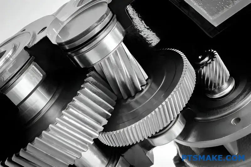
Når der ikke kan gås på kompromis med ydeevnen, er tandhjulsgear det eneste valg. Deres design er perfekt til anvendelser, der kræver jævn og støjsvag kraftoverførsel. Tænk på miljøer med høj hastighed og høj belastning.
Her kan tandhjul simpelthen ikke konkurrere. Den gradvise indkobling af de spiralformede tænder reducerer støj og vibrationer. Det gør dem uundværlige i bestemte industrier.
Højtydende applikationer
Transmissioner til biler
I biler, især elbiler, er støjreduktion afgørende. Spiralformede gear sikrer en rolig og jævn kørsel for passagererne.
Industrielle gearkasser
Pålidelighed er afgørende for tunge maskiner og turbiner. Spiralformede tandhjul håndterer højere belastninger og hastigheder og sikrer langvarig driftsstabilitet.
| Anvendelse | Vigtige krav | Hvorfor spiralformede tandhjul? |
|---|---|---|
| Biler | Stille drift | Vinklede tænder reducerer støj og vibrationer. |
| Turbiner | Højhastighedsstrøm | Jævn indkobling håndterer høje omdrejninger. |
| Industriel | Høj belastningskapacitet | Større tandkontakt fordeler stress. |
I debatten om tandhjulsgear kontra skrueformede gear er det anvendelsen, der afgør, hvem der vinder. Tandhjulsgear er effektive og enklere at fremstille, men de støjer ved høje hastigheder. Det skyldes den pludselige kontakt mellem tænderne.
Spiralformede tandhjul løser dette problem. De vinklede tænder griber gradvist ind på tværs af gearets overflade. Det giver en meget mere jævn og støjsvag kraftoverførsel. Vores test hos PTSMAKE viser konsekvent en betydelig reduktion i støj, vibrationer og hårdhed (NVH).
Den tekniske afvejning
Denne smidige drift har en bagside. De vinklede tænder producerer Aksialt tryk13En kraft, der skubber tandhjulene fra hinanden langs deres aksler. Denne kraft skal styres med passende lejer, f.eks. tryklejer.
Det gør designet mere komplekst og dyrt. Men til anvendelser, hvor ydeevnen er altafgørende, er det en nødvendig teknisk beslutning. Hvis man ignorerer det, kan det føre til for tidlig svigt.
Applikationsspecifikke fordele
| Funktion | Fordelen ved biler | Industrielle fordele |
|---|---|---|
| Glat engagement | Forbedret kørekomfort. | Reduceret slid på maskiner. |
| Kapacitet til høj hastighed | Velegnet til moderne motorer og elbiler. | Uundværlig for turbiner til elproduktion. |
| Større belastningskapacitet | Øget pålidelighed i transmissionen. | Længere levetid for kraftige gearkasser. |
Hos PTSMAKE guider vi kunderne gennem disse afvejninger. Vi hjælper dem med at vælge den rigtige geartype og designe de understøttende systemer for at sikre optimal ydeevne og holdbarhed til deres specifikke anvendelse.
I højhastighedssystemer med høj effekt, som f.eks. biltransmissioner og industriturbiner, er tandhjulsgear obligatoriske. Deres design sikrer jævn og støjsvag drift på trods af den ekstra kompleksitet, der er forbundet med at håndtere aksialt tryk. Tandhjulsgear er simpelthen for støjende til disse krævende anvendelser.
Hvordan er smørestrategien forskellig for tandhjul og skrueformede tandhjul?
Alle gear har brug for smøring, men valget af smøremiddel er ikke ens for alle. Strategien er meget forskellig, når man sammenligner tandhjulsgear med skrueformede gear.
Tandhjul fungerer ofte godt med almindelige smøremidler. Deres design med lige tænder resulterer primært i rullende kontakt. Det betyder mindre friktion og varmeudvikling.
Spiralformede tandhjul giver dog mere glidende bevægelse. Det skyldes deres vinklede tænder. Denne glidebevægelse kan skabe højere tryk og temperaturer ved kontaktpunkterne.
Nøglefaktorer for smøremidler
| Geartype | Primær kontakt | Krav til smøremiddel |
|---|---|---|
| Tandhjul | Rullende | Generelle formål, lavere viskositet |
| Spiralformet gear | Glidende og rullende | Højere viskositet, EP-additiver |
Denne skelnen er afgørende for den langsigtede performance.
Additiver til ekstreme tryk spiller en vigtig rolle
Glidebevægelserne i skrueformede tandhjul er hovedårsagen til de forskellige smørebehov. Denne glidning under belastning skaber en udfordring, som standardsmøremidler ikke altid kan håndtere. Det genererer betydelig friktionsvarme.
Denne varme kan nedbryde oliefilmen mellem tænderne. Når denne film svigter, får du metal-til-metal-kontakt, hvilket fører til slid og for tidlig slitage. Dette er en almindelig fejltilstand, som vi har set i applikationer med høj belastning.
For at forhindre dette har smøremidler til tandhjulsgear ofte brug for særlige tilsætningsstoffer. Det er her, smøremidler med specifikke Additiver til ekstremt tryk (EP)14 bliver ikke til forhandling.
Hvornår er EP-additiver nødvendige?
Baseret på vores test med kunder bliver behovet for EP-additiver tydeligt under specifikke forhold.
| Driftstilstand | Smøremiddel til tandhjul | Smøremiddel til tandhjulsgear |
|---|---|---|
| Lav hastighed, lav belastning | Standard gearolie | Standard gearolie |
| Høj hastighed, høj belastning | Standard gearolie | Olie med EP-additiver |
| Stødbelastning | Kan have brug for mild EP | Kræver robuste EP-additiver |
Disse additiver danner et beskyttende kemisk lag på gearets overflade. Dette lag fungerer som en sidste forsvarslinje, når oliefilmen er kompromitteret. Det forhindrer, at geartænderne svejses sammen under stærkt tryk. Hos PTSMAKE gennemgår vi altid driftsbelastningerne for at anbefale den rigtige smøremiddelstrategi.
Begge geartyper kræver smøring, men de højere glidekræfter i spiralformede gear kræver ofte smøremidler med EP-additiver. Dette valg er afgørende for at forhindre slitage og sikre drivlinjens pålidelighed, især under tunge belastninger.
Hvordan er følsomheden for gearjustering i forhold til de to?
Justering af gear er afgørende for ydeevne og levetid. Selv en lille fejljustering kan give store problemer.
Spiralformede tandhjul er generelt mere følsomme over for dette. Deres vinklede tænder kræver præcis positionering.
Uden den fordeles belastningen ikke jævnt. Det fører til støj, vibrationer og for tidlig svigt. Lad os undersøge, hvorfor det sker.
| Geartype | Følsomhed over for justering | Primær årsag |
|---|---|---|
| Stirnhjul | Mindre følsom (over for parallel) | Fuld linjekontakt langs tandfladen. |
| Spiralformede tandhjul | Mere følsom | Vinklet kontakt kræver perfekt akselparallelitet. |
Den kritiske karakter af akselopretning
I ethvert gearsystem er perfekt akselopretning målet. Men i virkeligheden er der altid små afvigelser. Hvordan hver enkelt geartype håndterer denne ufuldkommenhed, er en nøglefaktor i debatten om tandhjul kontra skrueformede tandhjul.
Spiralgearets følsomhed forklaret
Tandhjulsgear opnår deres jævne, støjsvage drift gennem gradvis tandindgreb. Kontakten starter i den ene ende af tanden og bevæger sig hen over dens overflade.
Denne gradvise kontakt er en styrke, men også en svaghed. Hvis skaftet er forskudt, koncentreres belastningen på én del af tanden. Det skaber lokaliserede trykpunkter, eller spændingskoncentration15hvilket fører til accelereret slid og grubetæring.
I vores arbejde hos PTSMAKE har vi set skrueformede gearsæt svigte tidligt på grund af mindre monteringsfejl. Det resulterende ujævne slidmønster er et tydeligt tegn på justeringsproblemer.
| Type af forskydning | Påvirkning af tandhjul | Påvirkning af tandhjul |
|---|---|---|
| Parallel | Høj. Får belastningen til at koncentrere sig i tændernes ender. | Moderat. Opretholder stadig linjekontakt, men ujævnt. |
| Vinkelformet | Meget høj. Ændrer drastisk kontaktmønster og belastning. | Høj. Fører til kantbelastning og høj stress. |
Tilgivelse af tandhjul
Tandhjul med lige tænder er mere tilgivende over for en lille forskydning af den parallelle aksel. Belastningen fordeles over hele tandfladen.
Selv om de ikke er immune, kan de bedre tolerere mindre ufuldkommenheder uden øjeblikkelig katastrofal svigt. Vinkelforskydninger er dog stadig meget skadelige.
Kort sagt kræver tandhjulsgear større præcision ved montering. Deres design, som giver jævn drift, gør dem også mere følsomme over for forskydning. Tandhjulsgear giver større tolerance, især for afvigelser i den parallelle aksel, hvilket gør dem mere robuste i nogle anvendelser.
Hvordan begrænser driftshastigheden deres respektive anvendelser?
Driftshastigheden er en kritisk faktor, når man skal vælge mellem cylindriske og spiralformede gear. Den har direkte indflydelse på støj, vibrationer og de dynamiske belastninger i et system.
For tandhjul er der en praktisk hastighedsgrænse. Deres design med lige tænder medfører en brat kontakt over hele linjen under indgrebet. Det skaber slagkræfter, som stiger med hastigheden.
Dette er en vigtig overvejelse i debatten om tandhjul og skrueformede tandhjul. Nedenfor er en hurtig sammenligning af deres hastighedsrelaterede egenskaber.
| Funktion | Stirnhjul | Spiralformede tandhjul |
|---|---|---|
| Hastighedens egnethed | Lav til moderat | Høj |
| Støj ved hastighed | Høj | Lav |
| Indvirkning på meshing | Betydelig | Minimal |
Denne pludselige indkobling er grunden til, at tandhjul bliver støjende og vibrerer ved højere hastigheder.
Udfordringen med hastighed med tandhjul
Det centrale problem med tandhjul ved høje hastigheder er deres geometri. Hele tandfladen går i indgreb på én gang. Tænk på det som en lille, hurtig hamrende effekt. Når gearet drejer hurtigere, bliver disse slag hyppigere og kraftigere.
Dette genererer betydelige dynamiske belastninger16Det belaster tandhjulene og skaber hørbar støj. Over en vis omdrejningshastighed kan denne vibration kompromittere hele systemets pålidelighed og ydeevne. Dette skaber effektivt en praktisk hastighedsgrænse for deres brug.
Hvorfor spiralformede tandhjul udmærker sig ved høje hastigheder
Spiralformede tandhjul overvinder denne begrænsning på elegant vis. Deres vinklede tænder sikrer, at kontakten begynder i den ene ende af tanden og fortsætter jævnt hen over dens overflade. Denne gradvise indgriben eliminerer de slagkræfter, der er karakteristiske for tandhjul.
Denne glatte indgriben giver mulighed for mere støjsvag drift og betydeligt mindre vibration. I de projekter, vi håndterer hos PTSMAKE, gør denne kvalitet tandhjulsgear til standardvalget til applikationer, der kræver høje omdrejningshastigheder, som i biltransmissioner eller industrielle præcisionsmaskiner.
| Hastighedsområde | Foretrukken geartype | Vigtig begrundelse |
|---|---|---|
| Lav til moderat | Tandhjul | Enkelhed og omkostningseffektivitet. |
| Høj | Spiralformet gear | Jævn, støjsvag drift og pålidelighed. |
Denne grundlæggende forskel i engagement er det, der adskiller deres anvendelsesområder fra hinanden.
Tandhjulsgear er begrænset af hastigheden på grund af slagkræfterne og støjen fra deres pludselige tandindgreb. Tandhjulsgear med deres gradvise indgreb fungerer jævnt og støjsvagt, hvilket gør dem vigtige til højhastighedsapplikationer, hvor pålidelighed og lav støj er afgørende.
Hvordan vælger man den rigtige geartype til en opgave?
At vælge det rigtige udstyr indebærer en struktureret proces. Det handler ikke kun om en enkelt specifikation. Du skal afveje flere nøglefaktorer.
Det sikrer, at det endelige valg opfylder alle præstationsmål. Jeg starter altid med de primære krav til anvendelsen.
Nøglefaktorer for beslutningstagning
En klar ramme forhindrer dyre fejl. Overvej disse fem kritiske områder, før du træffer en beslutning. Hver af dem påvirker gearets egnethed.
| Faktor | Beskrivelse |
|---|---|
| Hastighed (RPM) | Den nødvendige driftsmæssige rotationshastighed. |
| Drejningsmoment | Den rotationskraft, som gearet skal overføre. |
| Støjniveau | Det acceptable lydniveau under drift. |
| Budget | Omkostningsbegrænsningerne for komponenten. |
| Begrænsning af plads | Den fysiske plads, der er til rådighed for gearsystemet. |
En trin-for-trin udvælgelsesramme
Hos PTSMAKE guider vi vores partnere gennem en systematisk proces. Den starter med at definere de primære krav. Det sikrer, at det rigtige gear vælges til både ydeevne og fremstillingsmuligheder.
Et almindeligt udgangspunkt er valget mellem tandhjul og skrueformede tandhjul. Tandhjulsgear er effektive og omkostningseffektive til moderate hastigheder. Spiralformede gear kører mere jævnt og støjsvagt, hvilket gør dem ideelle til højhastigheds- eller støjfølsomme applikationer.
Men beslutningen er sjældent så enkel. Du skal overveje, hvordan forskellige geartyper klarer sig på tværs af alle kriterier. Præcisionsanvendelser introducerer også faktorer som modreaktion17hvilket kan være kritisk.
Beslutningsmatrix for valg af redskaber
Vi bruger ofte en beslutningsmatrix sammen med vores kunder. Dette værktøj hjælper med at visualisere kompromiserne mellem forskellige redskabstyper. Det giver en klar, datadrevet vej til den bedste løsning.
| Geartype | Hastighedsvurdering | Kapacitet for drejningsmoment | Støjniveau | Relative omkostninger | Effektivitet |
|---|---|---|---|---|---|
| Spor | Medium | Medium | Høj | Lav | Meget høj |
| Spiralformet | Høj | Høj | Lav | Medium | Høj |
| Skråkant | Medium | Medium | Medium | Høj | Høj |
| Orm | Lav | Meget høj | Meget lav | Medium | Lav-medium |
Denne matrix er et udgangspunkt. Din specifikke applikation vil afgøre den rette balance.
En struktureret beslutningsramme forenkler valg af gear. Ved at evaluere krav som hastighed, drejningsmoment, støj, budget og plads kan du systematisk identificere den optimale geartype til dine specifikke behov, så du undgår gætterier og sikrer pålidelig ydeevne.
Hvordan vælger man det rigtige materiale til et gear?
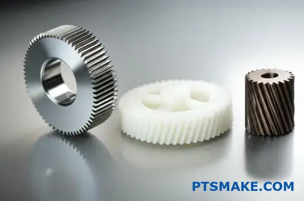
At vælge det rigtige gearmateriale er en kritisk beslutning. Det har direkte indflydelse på ydeevnen, levetiden og de samlede omkostninger for dit produkt. Din applikations specifikke krav skal være styrende for dit valg.
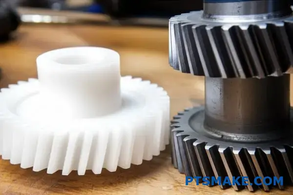
Tænk på faktorer som belastning, hastighed og driftsmiljø. Et stålgear med højt drejningsmoment til en biltransmission har helt andre behov end et støjsvagt plastikgear i en kontorprinter.
Her er en hurtig oversigt til at komme i gang:
| Materialekategori | Vigtig fordel | Almindelig brugssag |
|---|---|---|
| Stållegeringer | Høj styrke og holdbarhed | Transmissioner til biler |
| Plast | Støjsvag og korrosionsbestandig | Kontorudstyr, medicinsk udstyr |
| Bronzelegeringer | Lav friktion og tilpasningsevne | Snekkegear-drev |
Denne guide hjælper dig med at navigere i disse muligheder for dit projekt.
Lad os dykke dybere ned i en praktisk guide til materialevalg. Det bedste valg afbalancerer altid ydeevne og budget. Hos PTSMAKE starter vi ofte med at analysere de operationelle kræfter og miljøet for at finde denne balance.
Stållegeringer til højbelastningsopgaver
Når det gælder høj styrke og holdbarhed, er stål det bedste materiale. Det håndterer høje belastninger og slid usædvanligt godt, uanset om det drejer sig om tandhjul eller skrueformede tandhjul. Varmebehandling kan også forbedre dets egenskaber betydeligt.
| Stållegering | Bedst til | Nøglefunktion |
|---|---|---|
| 4140 stål | Højt drejningsmoment og hårdførhed | Evne til gennemhærdning |
| 8620 Stål | Slag og overfladeslid | Fremragende til indsatshærdning |
Plast til specialiserede anvendelser
Man skal ikke undervurdere plast. De løser almindelige problemer som støj, korrosion og behovet for ekstern smøring. Baseret på vores test er de ideelle til anvendelser med lettere belastning, hvor disse faktorer er kritiske.
Den unikke tribologiske egenskaber18 af plast gør dem uundværlige i mange moderne designs.
Populære plastmuligheder
- Delrin (Acetal): Kendt for sin lave friktion og fremragende dimensionsstabilitet. Vi anbefaler det til bevægelige præcisionsdele.
- Nylon: Giver god sejhed og kemisk modstandsdygtighed. Det er også fantastisk til at dæmpe støj og vibrationer.
Bronze til sammenkobling med lav friktion
Bronzelegeringer er et klassisk valg til visse geartyper. De er især almindelige til snekkehjul, der passer sammen med stålsnegle. Denne materialeparring giver meget lav friktion og forhindrer fastbrænding under tunge belastninger.
At vælge det rigtige gearmateriale er en afvejning. Stål giver styrke til høje belastninger. Plast giver støjsvag, korrosionsbestandig drift til lettere opgaver. Bronze udmærker sig i specifikke anvendelser med lav friktion. Nøglen er at matche materialet til din applikations unikke krav.
Hvordan ville du redesigne et støjende tandhjulsdrev, så det blev mere støjsvagt?
Et støjende tandhjulsdrev er en almindelig teknisk udfordring. Den mest effektive løsning indebærer ofte et komplet redesign. Det er ikke nok bare at udskifte dele.
Vi udskifter de støjende tandhjul med spiralformede tandhjul. Denne ændring reducerer støjen betydeligt. Men det kræver et omhyggeligt redesign af hele systemet.
Nøglen er at forstå forskellene mellem tandhjul og spiralformede tandhjul. De vinklede tænder i tandhjulsgear går gradvist i indgreb, og det er derfor, de kører mere støjsvagt.
| Geartype | Forlovelse | Støjniveau |
|---|---|---|
| Tandhjul | Pludselig | Høj |
| Spiralformet gear | Gradvis | Lav |
Dette redesign omfatter ændringer af geometri, lejer og hus.
Når vi redesigner et drev, så det bliver mere støjsvagt, går vi videre end til et simpelt gearskifte. Overgangen fra cylindriske til spiralformede gear er en grundlæggende teknisk ændring. Det påvirker hele den mekaniske enhed.
Genberegning af geargeometri
Det første skridt er at genberegne geargeometrien. Indførelsen af en helixvinkel ændrer alt. Det skaber et mere jævnt og gradvist tandindgreb. Det er den primære årsag til støjreduktionen. Vi skal justere trykvinklen og tandprofilen for at optimere kontakten og minimere sliddet.
Specificering af nye lejer
Tandhjulsgear genererer primært radiale belastninger. På grund af deres vinklede tænder producerer spiralformede gear både radiale og Aksialt tryk19. Denne nye kraft skal styres. Standardkuglelejer kan svigte. Vi skal specificere lejer, der er i stand til at håndtere trykbelastninger, såsom koniske rullelejer eller vinkelkontaktlejer.
Ændring af huset
De nye lejer og trykkræfter kræver ændringer af huset. Huset skal være stift nok til at understøtte det nye lejearrangement. Det skal forhindre enhver afbøjning af akslen under belastning. Hos PTSMAKE redesigner vi ofte huset for at sikre præcis justering og langsigtet pålidelighed.
| Design-aspekt | Tandhjulsdrev | Redesign af tandhjulsgear |
|---|---|---|
| Primær belastning | Radial | Radial og aksial |
| Lejetype | Enkelt kugleleje | Konisk/vinkelformet kontakt |
| Boliger | Standard stivhed | Forstærket til tryk |
| Støj | Høj | Lav |
At skifte til spiralformede gear for at opnå støjsvag drift er ikke bare en udskiftning. Det er et omfattende redesign, der involverer ny geometri, specialiserede lejer til at håndtere tryk og et modificeret hus. Det sikrer et virkelig støjsvagt og pålideligt system.
Hvordan optimerer man et geardesign, så det vejer mindst muligt?
I kritiske anvendelser som rumfart betyder hvert gram noget. Avancerede strategier er afgørende. Vi bevæger os ud over grundlæggende design for at opnå minimal vægt.
Højtydende materialer
Det første skridt er at vælge materialer som højstyrkestållegeringer eller titanium. De giver et overlegent forhold mellem styrke og vægt.
Avancerede varmebehandlinger
Processer som nitrering eller karburering hærder gearets overflade. Det øger belastningskapaciteten. Det gør det muligt at bruge et mindre og lettere gear til at udføre det samme arbejde.
Optimering af gearemne
Det er en vigtig teknik at spænde redskabets emne ud. Vi fjerner strategisk materiale fra gearets krop. Det reducerer vægten uden at påvirke det kritiske tandområde.
| Strategi | Indvirkning på vægten | Overvejelser |
|---|---|---|
| Avancerede materialer | Høj | Højere materialeomkostninger |
| Varmebehandling | Medium | Yderligere procestrin |
| Bånd | Høj | Kompleks bearbejdning |
Avanceret vægtoptimering kræver en holistisk tilgang. Det handler om at kombinere materialevidenskab, varmebehandling og intelligent geometrisk design for at skabe et gear, der både er stærkt og utroligt let.
Optimering af gearets kernestruktur
At spænde et gearemne ud er mere kunst end videnskab. Det indebærer bearbejdning af lommer af materiale fra gearets centrale skive. Det fjerner ikke-væsentlig masse. Målet er at skabe en egelignende eller vævet struktur. På den måde bevares stivheden, samtidig med at vægten reduceres drastisk. I tidligere projekter hos PTSMAKE har vi opnået en betydelig vægtreduktion på denne måde.
| Geartype | Relativ vægt | Kompleksitet |
|---|---|---|
| Solid blank | 100% | Lav |
| Webbed Blank | 60-75% | Høj |
Tandprofil og styrke
Ud over emnet er ændringer af tandprofilen afgørende. En subtil justering som at tilføje kroning20 kan sikre, at belastningen fordeles jævnt over tandfladen, selv ved små forskydninger. Det forhindrer spændingskoncentrationer ved tandenderne.
Denne forbedrede belastningsfordeling betyder, at gearet kan klare mere stress. Derfor kan vi designe det til at være mindre og lettere fra starten. Dette princip er en vigtig overvejelse i debatten om tandhjulsgear vs. skruegear, da hver type reagerer forskelligt på sådanne ændringer. Ved at kombinere disse designtilpasninger med overlegne materialer og varmebehandlinger kan vi levere førsteklasses letvægtsgear til krævende industrier.
Optimering til minimal vægt indebærer brug af materialer med høj styrke og avancerede varmebehandlinger. Smart design, som f.eks. at udspænde gearemnet og ændre tandprofilen, fjerner ikke-væsentlig masse uden at gå på kompromis med gearets strukturelle integritet eller ydeevne.
Hvornår ville du med vilje vælge et tandhjul i plast frem for stål?
Det er let at tro, at stål altid er bedre. Det er stærkere, ikke sandt? Men styrke er ikke den eneste faktor. Til mange anvendelser er et tandhjulsgear i plast det smartere og mere effektive valg.
Det gælder især, når prioriteterne skifter. Tænk på lav støj, selvsmøring eller korrosionsbestandighed. I disse tilfælde er plast ofte bedre end metal. Omkostninger er også en vigtig drivkraft.
| Funktion | Fordele ved plastgear | Fordele ved stålgear |
|---|---|---|
| Støj | Meget lav | Kan være høj |
| Smøring | Selvsmørende | Kræver eksternt smøremiddel |
| Omkostninger | Lavere, især i store mængder | Højere materiale- og bearbejdningsomkostninger |
| Vægt | Letvægt | Tungt |
Ud over råstyrke: Applikationsspecifikke valg
I vores arbejde hos PTSMAKE vejleder vi kunder om materialevalg. Det handler om at matche materialet til det virkelige miljø. Ren styrke er ofte overkill.
Kontor- og forbrugerelektronik
Tænk på en printer eller en scanner. Disse enheder står på kontorer eller i hjemmet. De skal køre stille og roligt. Stålgear ville skabe for meget støj.
Tandhjul af plast er perfekte her. De arbejder næsten lydløst. De har heller ikke brug for fedt, som kan plette papir eller beskadige elektronik. Deres fremragende tribologiske egenskaber21 sikrer lang levetid uden vedligeholdelse.
Miljøer med risiko for korrosion
Hvad med en enhed, der bruges i nærheden af vand eller kemikalier? Stålgear ville ruste og hurtigt gå i stykker. Rustfrit stål er en mulighed, men det er dyrt.
Plastgear er naturligt immune over for korrosion. Det gør dem ideelle til udstyr til fødevareforarbejdning, medicinsk udstyr eller udendørs produkter. De giver pålidelig ydeevne, hvor stål ikke kan. Når man sammenligner tandhjul med skrueformede tandhjul til disse anvendelser, betyder materialet ofte mere end geartypen for levetiden.
| Anvendelsesområde | De vigtigste fordele ved plast |
|---|---|
| Kontorprintere | Støjsvag, ingen smøring nødvendig |
| Medicinsk udstyr | Steriliserbar, korrosionsbestandig |
| Fødevareforarbejdning | Kemikalieresistens, ingen forurening |
| Legetøj og gadgets | Lav pris, letvægt, sikker |
Kort sagt handler det ikke om at gå på kompromis, når man vælger plast frem for stål. Det er en strategisk beslutning. Den prioriterer omkostningseffektivitet, lav støj og vedligeholdelsesfri drift i applikationer, hvor højt drejningsmoment og ekstrem styrke ikke er de primære krav.
Analyser virkningen af at udskifte et tandhjulsgear med et skrueformet gear på effektiviteten.
Det er en almindelig opfattelse, at jævnere drift er lig med højere effektivitet. Men i debatten om tandhjul vs. skrueformede tandhjul er det ikke altid tilfældet.
Mens spiralformede tandhjul giver en mere stille og gradvis indkobling, skaber deres vinklede tænder en unik dynamik. Det ændrer de kræfter, der er på spil.
Kilden til ineffektivitet
Den primære forskel ligger i typen af kontakt mellem tænderne. Dette er et subtilt, men kritisk punkt for enhver designingeniør.
| Geartype | Primær kontakt Bevægelse | Resultat |
|---|---|---|
| Tandhjul | Rullende/glidende | Direkte kraftoverførsel |
| Spiralformet gear | Øget glidning | Glattere, men mere friktion |
Denne øgede glidevirkning langs tandfladen er nøglen. Det genererer lidt mere friktion og varme sammenlignet med et tandhjul.
Et dybere kig på friktion og kræfter
Lad os se nærmere på denne afvejning. Et tandhjuls tænder griber ind i hinanden med en bevægelse, der stort set er rullende, med lidt glidning. Det er en meget effektiv måde at overføre kraft på.
Spiralformede tandhjul har på grund af deres spiralformede vinkel tænder, der glider i indgreb. Denne kontinuerlige glidekontakt reducerer støj og stødbelastninger, hvilket er en betydelig fordel.
Men denne glidende bevægelse skaber mere friktion end den primært rullende kontakt i tandhjul. Baseret på vores interne test kan dette resultere i et mindre effektivitetstab, typisk i størrelsesordenen 1-3%, afhængigt af anvendelse og smøring.
Forståelse af kompromiserne
Det spiralformede design skaber også en kraft parallelt med gearets akse. Denne Aksialt tryk22 skal styres af passende lejer, som kan indføre deres egne friktionstab i systemet. Valget er ikke altid enkelt.
| Funktion | Tandhjul | Spiralformet gear |
|---|---|---|
| Betjening | Højere | Mere støjsvag, mere jævn |
| Tandkontakt | Linjekontakt | Gradvist engagement |
| Effektivitet | Meget høj | Lidt lavere |
| Aksial belastning | Ingen | Ja |
Hos PTSMAKE arbejder vi ofte sammen med kunderne om at analysere disse subtile punkter. At vælge den rigtige geartype afhænger helt af applikationens specifikke prioriteter - det være sig støjniveau, belastningskapacitet eller maksimal effektivitet.
Spiralformede gear giver en mere jævn og støjsvag ydelse. Men deres vinklede tænder øger glidefriktionen. Det skaber et lille, men vigtigt kompromis med effektiviteten i forhold til tandhjulenes mere direkte rullevirkning.
Få ekspertløsninger til tandhjul og tandhjulsgear med PTSMAKE
Er du klar til præcisionsgearløsninger? Samarbejd med PTSMAKE om specialfremstillede tandhjul og tandhjulsgear - konstrueret efter dine krævende standarder. Send din forespørgsel nu, og oplev pålidelig kommunikation, snævre tolerancer, hurtige leveringstider og et ægte engagement i din succes.

Forstå den afgørende rolle, som denne cirkel spiller i definitionen af hele den evolverede tandprofil. ↩
Lær, hvordan du håndterer denne kraft for at få et optimalt gearsystem og en lang levetid. ↩
Lær, hvordan denne kritiske geometriske funktion påvirker kraftfordelingen og gearets effektivitet. ↩
Dyk dybere ned i, hvordan forskellige kraftvektorer kombineres i gearsystemer. ↩
Se vores detaljerede guide for at forstå, hvordan geargeometri påvirker ydeevnen. ↩
Forstå, hvordan denne mekaniske egenskab påvirker vibrations- og støjniveauet i gearsystemer. ↩
Udforsk, hvordan den progressive kontaktlinje på spiralformede tænder sikrer en mere jævn og støjsvag kraftoverførsel. ↩
Forstå, hvordan denne kraft påvirker geardesignet, og hvilke lejer der er nødvendige for at håndtere den effektivt. ↩
Forstå, hvordan overfladespændingsanalyse kan forhindre for tidlig gearfejl. ↩
Forstå, hvordan denne kraft påvirker gearets design og valget af passende lejer. ↩
Lær, hvordan denne kraft påvirker gearets design og levetid. ↩
Udforsk, hvordan disse pumper bruger præcis gearmekanik til at flytte væsker med enestående nøjagtighed. ↩
Lær, hvordan du beregner og håndterer denne kraft i dine designs. ↩
Opdag, hvordan disse kemiske tilsætningsstoffer forhindrer katastrofale gearfejl under ekstreme belastninger. ↩
Lær, hvordan spændingskoncentration påvirker materialetræthed og komponenternes levetid. ↩
Forstå, hvordan disse variable kræfter påvirker gearets levetid og systemets ydeevne. ↩
Få mere at vide om gearets slør, og hvordan man minimerer det ved CNC-bearbejdning med høj præcision. ↩
Lær, hvordan friktion, slid og smøreegenskaber bestemmer dit gears ydeevne og levetid. ↩
Forstå, hvordan denne kraft påvirker geardesign og valg af lejer for at opnå optimal ydelse. ↩
Opdag, hvordan denne subtile tandmodifikation drastisk kan forbedre gearets indgreb og forlænge dets levetid. ↩
Få mere at vide om, hvordan friktion, slid og smøring påvirker gearmaterialers ydeevne. ↩
Forstå, hvordan denne kraft påvirker valg af lejer og systemdesign. ↩