Getting press fit calculations wrong can destroy expensive parts, halt production lines, and compromise safety-critical assemblies. Even experienced engineers struggle with the complex interactions between interference values, material properties, thermal effects, and assembly forces that determine whether a press fit will hold securely or fail catastrophically.
Press fit calculations involve determining the precise interference between mating parts, calculating resulting contact pressures using material properties and geometric relationships, then verifying that stresses remain within safe limits while providing adequate load transmission capacity.

This guide covers the essential formulas, decision-making frameworks, and practical considerations I use when designing reliable press fits. You’ll learn how to handle everything from basic interference calculations to complex scenarios involving different materials, thermal assembly methods, and safety factor selection.
What is the fundamental principle behind a press fit?
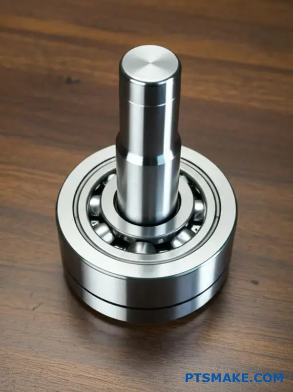
A press fit, also known as an interference fit, relies on a simple yet powerful concept: friction. The entire principle is built on creating a joint where the shaft is intentionally made slightly larger than the hole it fits into.
This dimensional overlap is called "interference."
When the two parts are forced together, this size difference generates significant radial pressure. This pressure creates a strong frictional force that locks the components together, preventing them from slipping. It’s a purely mechanical bond.
| Component | Relative Size | Key Factor |
|---|---|---|
| Shaft | Larger than the hole | Positive Interference |
| Hub (Hole) | Smaller than the shaft | Controlled Deformation |
This method is highly effective for transmitting torque and axial loads without needing fasteners.
The Science of Stored Energy
When a press fit is assembled, the materials of both components deform elastically. The outer component, the hub, stretches to accommodate the oversized shaft. The inner shaft is compressed by the smaller hole.
This deformation stores potential energy within the assembly, like a compressed spring. This stored energy creates a constant and uniform contact pressure between the two surfaces.
This is the radial pressure1 that is fundamental to the joint’s strength. It’s what generates the static friction needed to hold the parts securely. A precise press fit calculation is essential to get this right.
At PTSMAKE, we’ve seen how critical tight tolerances are. If the interference is too great, it can over-stress the material, potentially causing cracks or failure.
| Fit Type | Shaft-to-Hole Relationship | Common Use Case |
|---|---|---|
| Clearance Fit | Shaft is smaller | Rotating shafts, sliding parts |
| Transition Fit | Tolerances overlap | Locating pins, spigots |
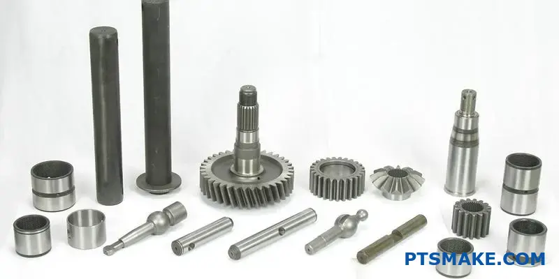
| Interference Fit | Shaft is larger | Bearings, gears, bushings |
Conversely, if the interference is too small, the joint may fail under its intended load. That’s why our CNC machining processes are so focused on precision. We ensure every component meets the exact specifications for a reliable fit.
A press fit’s strength comes from the interference between a shaft and a hole. This size difference creates high radial pressure and static friction, locking the parts together to transmit loads without any fasteners. This makes it a simple and robust joining method.
How does interference generate contact pressure?
Interference is essentially a planned dimensional overlap. We force a larger part (like a shaft) into a smaller hole. This physical overlap is the starting point.
The Material’s Reaction
The materials of both parts don’t just yield. They push back. The hole expands, and the shaft compresses. This internal resistance is what creates force.
From Force to Pressure
This force is distributed over the contact area between the two components. This distributed force is the contact pressure. It’s the "grip" that holds the assembly together. A proper press fit calculation ensures this pressure is just right.
Hooke’s Law in Action
At its core, this process follows Hooke’s Law. The law states that stress is proportional to strain. In simpler terms, the more you deform a material, the more it pushes back. The interference is the "strain" we apply to the system.
The material’s inherent stiffness dictates the amount of "stress" or pressure it generates. This stiffness is quantified by a property called Young’s Modulus. Materials with a high Young’s Modulus, like steel, will generate more pressure for the same amount of interference compared to a softer material like aluminum. This is because they resist elastic deformation2 more strongly.
Material Selection is Key
Choosing the right materials is critical. At PTSMAKE, we often guide clients on material selection based on the required holding force. The choice directly impacts the press fit calculation and the assembly’s performance.
Let’s compare two common materials.
| Material | Young’s Modulus (GPa) | Resulting Pressure |
|---|---|---|
| Steel | ~200 | High |
| Aluminum | ~70 | Lower |
This table shows that for the same interference, steel creates a much stronger joint because it is stiffer.
The interaction is simple: you create a dimensional conflict (interference). The materials’ elasticity (Young’s Modulus) resists this conflict, generating a predictable force. This force, spread over the contact surface, becomes the contact pressure that holds the parts securely.
What are the primary stresses in a press fit assembly?
In any press fit assembly, two critical stresses emerge. These are radial stress and tangential stress.
Tangential stress is often called ‘hoop’ stress. It acts along the circumference of the hub and shaft.
Radial stress acts perpendicular to the surface. It pushes outward on the hub and inward on the shaft. Understanding both is key for a successful design.
Here’s a quick breakdown:
| Stress Type | Effect on Hub | Effect on Shaft |
|---|---|---|
| Radial Stress | Tensile (Pulls outward) | Compressive (Squeezes inward) |
| Tangential (Hoop) Stress | Tensile (Stretches) | Compressive (Squeezes) |
Understanding Stress Origins
These stresses are born from the interference itself. The larger shaft forces the smaller hub hole to expand. This action creates the holding force.
Hoop Stress in the Hub
As the hub stretches to accommodate the shaft, its material is pulled apart along the circumference. This creates tensile hoop stress.
If this stress exceeds the material’s yield strength, the hub can crack or fail. It’s a critical factor in our press fit calculation.
Radial Stress at the Interface
The pressure between the mating surfaces creates radial stress. This stress is compressive on the shaft’s surface, squeezing it.
On the hub’s inner surface, this same pressure acts as a tensile force, pulling the material outward. The entire assembly’s integrity depends on the material’s response to this Elastic deformation3 without failure.
In our work at PTSMAKE, we carefully analyze these forces to ensure the joint remains secure under operational loads. The interaction between these stresses determines the joint’s strength.
| Component | Primary Stresses | Nature of Stress |
|---|---|---|
| Hub | Hoop & Radial | Tensile |
| Shaft | Radial & Hoop | Compressive |
A press fit assembly is defined by radial and tangential (hoop) stresses. Radial stress compresses the shaft and puts the hub in tension. Hoop stress creates tension in the hub. Proper calculation ensures these forces create a strong, lasting joint.
What defines a successful versus a failed press fit?
A press fit has one primary job. It must securely join two parts. Success is defined by its ability to transmit the required load without any movement.
This means no slipping under torque. It also means no damage to the components during assembly or use.
Failure, however, can manifest in several ways. It is not always as simple as the parts coming loose. Understanding these failure points is critical. A precise press fit calculation is the foundation for avoiding them.
Key Indicators of Success
| Criteria | Description |
|---|---|
| Load Transmission | The joint consistently handles the specified axial and torsional loads. |
| No Slipping | The interference creates enough frictional force to prevent relative motion. |
| Component Integrity | Neither the shaft nor the hub shows signs of cracking or yielding. |
A successful press fit is all about balance. The design must create enough interference for a strong grip. But too much interference leads directly to failure. Over the years, we’ve helped clients navigate this delicate balance.
Common Failure Modes to Avoid
When the balance is off, you get problems. Slipping occurs when interference is too low. The frictional force simply can’t resist the operational loads. This often points to manufacturing tolerances not being met.
Hub cracking is the opposite issue. Too much interference over-stresses the outer component. The resulting hoop stress4 can exceed the material’s tensile strength, leading to a fracture.
Shaft yielding happens when the shaft material can’t withstand the compressive forces. It permanently deforms, which reduces the interference and weakens the joint significantly.
Fretting corrosion is a more gradual failure. Small, repetitive movements between the surfaces cause wear and oxidation, slowly degrading the fit.
| Failure Mode | Primary Cause |
|---|---|
| Slipping | Insufficient interference or low coefficient of friction. |
| Hub Cracking | Excessive interference or brittle hub material. |
| Shaft Yielding | Excessive interference or soft shaft material. |
| Fretting Corrosion | Micro-motion between surfaces under load. |
Success hinges on a design that respects material limits and manufacturing that achieves tight tolerances. It’s a partnership between engineering theory and shop-floor precision.
A successful joint is a quiet one—it simply works without issue. Failure modes are varied, from slipping to cracking, each caused by an imbalance in force and material strength. Precision in both calculation and machining is the only way to ensure success.
How do dimensional tolerances create minimum and maximum interference?
In manufacturing, we must plan for the extremes. These are the ‘worst-case’ scenarios. They are defined by the tolerance bands of the shaft and hub.
This helps us find the tightest and loosest possible fits. We calculate both to ensure the assembly always works.
Understanding the Extremes
Maximum interference happens when the shaft is at its largest size. At the same time, the hub is at its smallest.
Minimum interference is the opposite. It occurs when the shaft is at its smallest allowable size, and the hub is at its largest.
| Scenario | Shaft Condition | Hub Condition | Resulting Interference |
|---|---|---|---|
| Worst-Case Tightest | Largest (Upper Limit) | Smallest (Lower Limit) | Maximum Interference |
| Worst-Case Loosest | Smallest (Lower Limit) | Largest (Upper Limit) | Minimum Interference |
To guarantee a successful interference fit, engineers must calculate these two boundary conditions. Ignoring them leads to assemblies that either fail under load or crack during assembly. At PTSMAKE, this is a fundamental step in our design for manufacturability (DFM) review.
Why ‘Worst-Case’ Thinking is Crucial
Thinking in terms of worst-case scenarios protects the design’s integrity. It ensures that even with manufacturing variations, every single part combination will function as intended. This process is essential for a reliable press fit calculation.
Calculating Maximum Interference
This calculation predicts the highest possible stress on the components. It’s found by taking the shaft’s maximum allowable diameter and subtracting the hub’s minimum allowable diameter. This ensures the material won’t yield or fracture. We must account for how tolerance stacking5 can influence the final assembly dimensions.
Calculating Minimum Interference
This calculation ensures the assembly has enough holding power. It is found by taking the shaft’s minimum diameter and subtracting the hub’s maximum diameter. This guarantees the joint won’t slip or fail under its operational loads.
Here’s how the formulas work in a proper press fit calculation:
| Interference Type | Formula | Purpose |
|---|---|---|
| Maximum (I_max) | Max Shaft Diameter – Min Hub Diameter | Prevents material failure |
| Minimum (I_min) | Min Shaft Diameter – Max Hub Diameter | Ensures sufficient holding force |
Calculating these ‘worst-case’ scenarios using tolerance bands is critical. It defines the absolute boundaries for your interference fit, ensuring the assembly is neither too tight to cause damage nor too loose to fail, guaranteeing functional reliability for every part produced.
What effect does surface roughness have on the effective interference?
Even the most precisely machined surface isn’t perfectly smooth. Under a microscope, it has tiny peaks and valleys. This is what we call surface roughness.
When two parts are pressed together, these microscopic peaks are the first points of contact. The immense pressure of the assembly flattens or crushes these peaks. This process is often called asperity flattening.
The Initial Contact
Imagine two rough surfaces meeting. Only the highest peaks touch initially. The actual contact area is much smaller than the total surface area.
Impact of Assembly Force
As force is applied, these peaks deform. This reduces the initial, designed interference. The loss of interference depends on the surface finish.
A comparison of the initial state and the post-assembly state is shown below.
| State | Surface Peak Condition | Effective Interference |
|---|---|---|
| Before Assembly | Peaks are intact and sharp | At maximum design value |
| After Assembly | Peaks are flattened/crushed | Reduced from design value |
This initial reduction is a critical factor.
The reduction in interference due to asperity flattening is not just a minor detail. It can be a significant portion of the total interference, especially in high-precision fits. Ignoring it leads to a weaker joint than intended.
Why Geometric Interference Isn’t the Whole Story
Geometric interference is what you calculate from the drawings. It assumes perfect, smooth cylinders. The effective interference, however, is what remains after the asperities have been flattened.
This is where experience in precision manufacturing becomes vital. At PTSMAKE, we factor this into our process. We understand that the material properties play a huge role.
Material Hardness and Ductility
Harder materials resist this flattening more than softer ones. A hardened steel shaft will flatten less than a softer aluminum hub. This process involves significant plastic deformation6 at the microscopic level. A proper press fit calculation must account for these material-dependent changes.
The table below gives a general idea based on our experience with clients’ projects.
| Material Property | Effect on Asperity Flattening | Impact on Interference Loss |
|---|---|---|
| High Hardness | Less flattening | Lower loss |
| Low Hardness | More flattening | Higher loss |
| High Ductility | Peaks deform easily | Higher loss |
| Low Ductility | Peaks may fracture | Complex, can lower loss |
Understanding this interaction is key. It ensures the final assembly has the required strength and holding force.
Asperity flattening is the crushing of microscopic surface peaks during assembly. This process reduces the designed geometric interference, directly affecting the final strength and tightness of the press fit. Material properties are a key factor in how much interference is lost.
What are the main types of press fit assembly methods?
Choosing the right press fit assembly method is crucial. It directly impacts joint strength, component integrity, and manufacturing efficiency. Each approach has specific benefits.
The three primary methods are force pressing, thermal expansion, and thermal contraction. We will explore each one. Understanding them helps you select the best technique for your application.
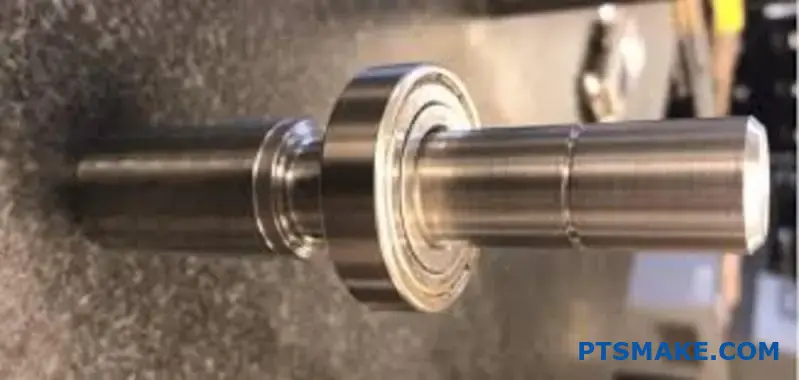
Force Pressing at Ambient Temperature
This is the most common method. We use a hydraulic or arbor press. It physically forces the shaft into the hub at room temperature. It’s simple and fast.
Thermal Methods
Thermal methods change the size of parts. This makes assembly easier.
Thermal Expansion (Heating the Hub)
We heat the outer component (the hub). This causes it to expand. The shaft then slides in easily. As the hub cools, it creates a strong joint.
Thermal Contraction (Cooling the Shaft)
Conversely, we can cool the inner part (the shaft). This is often done with liquid nitrogen. The shaft shrinks, allowing for easy insertion into the hub.
Each press fit method serves different needs. The choice depends on materials, tolerances, and assembly forces. An accurate press fit calculation is the first step, defining the required interference.
Force pressing is straightforward. However, it can introduce high stress. It also risks damaging component surfaces through scoring or galling7. This is a concern for parts with delicate finishes or those made from softer materials. We often use it when assembly forces are manageable and surface finish is less critical.
Thermal methods are gentler. They avoid the friction and potential surface damage of force pressing. Heating the hub is great for larger components. Cooling the shaft is ideal for sensitive assemblies where heating could damage nearby electronics or seals. Thermal methods require more equipment and precise temperature control. This can increase cycle time and cost.
At PTSMAKE, we guide clients through this selection process. We help balance performance needs with manufacturing realities.
Here is a comparison of the methods:
| Method | Key Advantage | Main Disadvantage | Best For |
|---|---|---|---|
| Force Pressing | Simple, fast, low equipment cost | Risk of surface damage, high stress | Small parts, robust materials |
| Thermal Expansion | Low assembly stress, no surface damage | Requires heating equipment, longer cycle | Large components, tight fits |
| Thermal Contraction | Very low stress, clean process | Cost of cryogenics, safety precautions | Sensitive materials, high-precision fits |
Choosing the right assembly method is a critical decision. Force pressing offers simplicity, while thermal methods provide a gentler assembly for sensitive or high-precision components. The best choice balances cost, time, and the integrity of the final product.
How do ISO 286 fit standards (e.g., H7/p6) simplify design?
The ISO system simplifies design by using a clear structure. It relies on standardized codes to define tolerance zones. This removes guesswork from engineering.
The Building Blocks of ISO 286
The system has three core components. Each part of a code like "H7" has a specific meaning. This creates a universal language for fits.
| Component | Description |
|---|---|
| Basic Size | The nominal diameter of the hole or shaft (e.g., 50 mm). |
| Fundamental Deviation | A letter defining the tolerance zone’s position relative to the basic size. |
| Tolerance Grade (IT) | A number (e.g., 7) that specifies the size of the tolerance zone. |
This structure ensures every engineer and machinist understands the required precision.
Hole-Basis vs. Shaft-Basis Systems
The ISO system offers two primary methods. Most designs use the hole-basis system for simplicity and cost-effectiveness. It is easier to produce shafts to various sizes than holes.
In a hole-basis system, the hole is the constant. The hole’s lower deviation is always zero (designated by "H"). The shaft’s tolerance is then varied to achieve the desired fit. This standardizes tooling like reamers and gauges.
At PTSMAKE, we typically recommend the hole-basis system. It simplifies tooling inventory and reduces manufacturing costs for our clients. The shaft-basis system is used in special cases. For example, when using standard-sized shafts like commercial bearings.
Decoding the H7/p6 Fit
Let’s break down a common interference fit: H7/p6. This code instantly communicates the engineering intent. This predictability is vital for an accurate Press fit calculation.
| Code | Component | Meaning for a 50mm Part |
|---|---|---|
| H | Hole Deviation | The hole’s tolerance zone starts at the basic size (zero deviation). |
| 7 | Hole Tolerance Grade | The hole has a specific tolerance range (e.g., 25 microns for a 50mm hole). |
| p | Shaft Deviation | The shaft’s tolerance zone is entirely above the basic size. |
| 6 | Shaft Tolerance Grade | The shaft has a tighter tolerance range (e.g., 16 microns for a 50mm shaft). |
This combination guarantees an interference fit. The smallest shaft will always be larger than the largest hole. The exact amount of interference, however, depends on the fundamental deviation8 and IT grade.
The ISO system’s structure uses standardized codes to define tolerance zones. This creates a predictable framework for holes and shafts, ensuring designers can specify and achieve the exact fit—clearance, transition, or interference—required for any application.
How do material combinations (e.g., steel/aluminum) affect calculations?
Combining materials like steel and aluminum is a common engineering practice. However, it significantly complicates design calculations.
You can’t treat the assembly as a single material.
Two properties are absolutely critical: Young’s Modulus and the coefficient of thermal expansion.
These factors directly influence stress distribution and performance, especially when temperatures fluctuate. An accurate press fit calculation depends on getting this right.
The Role of Young’s Modulus
Think of Young’s Modulus as a measure of stiffness. Different materials deform differently under the same load.
Steel is roughly three times stiffer than aluminum.
When you combine them, the stiffer material—steel—will bear a much larger share of the stress. This uneven distribution must be accounted for in your calculations to avoid overloading one component.
| Property | Steel (Typical) | Aluminum (Typical) |
|---|---|---|
| Young’s Modulus (GPa) | 200 | 70 |
| CTE (µm/m·°C) | 12 | 23 |
The Impact of Thermal Expansion
Materials expand when heated and contract when cooled. The problem is, they do so at different rates.
As our tests show, aluminum expands nearly twice as much as steel for the same temperature change.
This difference creates powerful internal forces. In an assembly, this differential thermal expansion9 can either loosen a joint or create immense stress.
Real-World Example
Imagine an aluminum ring press-fit onto a steel shaft. As the assembly heats up, the aluminum ring expands more than the steel shaft.
This reduces the interference, potentially causing the fit to loosen and fail.
Conversely, at very low temperatures, the aluminum contracts more, dramatically increasing the pressure and stress on both parts. This can lead to cracking.
In short, mixing materials requires careful analysis. Differences in stiffness and thermal expansion create complex stresses. Ignoring these, especially under varying temperatures, is a direct path to assembly failure. A precise press fit calculation is essential for reliability.
What is the difference between calculating for a solid vs. hollow shaft?
When calculating stress, the boundary conditions are key. For a solid shaft, the math is simpler. We mainly focus on the outer surface.
Hollow shafts are different. They have both an inner and an outer surface. Each can experience pressure. This changes everything. The stress distribution is no longer linear from the center.
Key Differences in Conditions
| Feature | Solid Shaft | Hollow Shaft |
|---|---|---|
| Pressure Surfaces | Outer only | Inner and Outer |
| Stress at Center | Zero (Theoretically) | N/A (Material is absent) |
| Calculation Model | Torsion Formula | Lamé’s Equations |
This shift requires a more complex approach.
Analyzing Stresses in Hollow Shafts
A solid shaft’s stress calculation is direct. Stress is zero at its center. It reaches its maximum at the outermost fiber. This is straightforward for torsional or bending loads.
Hollow shafts introduce complexity. They have two boundaries: the inner and outer diameters. Both can be under pressure. This is common in hydraulic systems or in a press fit calculation.
We use Lamé’s equations to solve this. These equations help us find the radial and hoop stresses throughout the cylinder’s wall thickness.
Understanding Stress Components
Internal pressure creates tension. It tries to expand the shaft. External pressure creates compression. It tries to crush the shaft. These forces result in both radial stress (acting along the radius) and hoop stress10 (acting circumferentially).
The final stress at any point is a combination of these factors. It’s not a simple linear gradient. At PTSMAKE, we model this carefully. This ensures the part withstands all operational pressures without failing. We found this essential for high-reliability components in the aerospace and medical fields.
Solid shaft calculations are simple, with stress maxing out at the surface. Hollow shafts are more complex. Their internal and external pressures require using Lamé’s equations to accurately determine radial and hoop stresses throughout the material.
What are the typical safety factors used in press fit design?
Safety factors in press fit design are not a single number. They are categorized based on what they protect against. This choice is critical for reliability.
We generally consider two main areas: material yield strength and the required load transmission. The right factor depends on the application’s importance and conditions.
Factors Applied to Material Strength
This ensures the hub and shaft materials do not permanently deform or fail. A higher factor protects against yielding under stress.
Factors for Load Transmission
This guarantees the joint can handle the required torque or axial force without slipping. The choice here is vital for functional performance.
A basic guideline for these factors is shown below.
| Application Area | Typical Safety Factor (SF) |
|---|---|
| Material Yield Strength | 1.2 to 2.0 |
| Required Load Transmission | 1.5 to 3.0 |
Choosing the right safety factor requires a deeper look into the specific application. It’s a balance of risk, cost, and performance. We must consider several key elements. A precise press fit calculation depends on these inputs.
Application Criticality
The more critical the part, the higher the safety factor. A failure in an aerospace component has severe consequences. This is different from a non-essential part in a consumer electronic device.
For high-risk applications, we often use safety factors at the upper end of the range. This provides an extra margin of safety against unforeseen events.
Loading Type and Conditions
The nature of the load is a major driver. A static load is much simpler to design for than a dynamic or cyclic load.
- Static Loads: Lower safety factors are often acceptable.
- Dynamic/Cyclic Loads: These can cause fatigue. They demand higher safety factors to prevent failure over time.
Material fatigue and potential Hertzian contact stress11 at the interface must be carefully managed.
Uncertainty in Design
Uncertainty comes from many sources. These include variations in material properties, manufacturing tolerances, and surface finishes. At PTSMAKE, we control tolerances tightly to reduce this uncertainty. But it can never be fully eliminated. A higher safety factor helps account for these unknowns.
| Factor | Influence on Safety Factor (SF) |
|---|---|
| High Criticality | Increase SF |
| Dynamic Loading | Increase SF |
| High Uncertainty | Increase SF |
| Well-Defined Conditions | Decrease SF |
In press fit design, safety factors are categorized for material strength and load transmission. The final choice is a careful decision based on application criticality, load type, and design uncertainties to ensure both safety and performance.
What calculation adjustments are needed for tapered press fits?
When dealing with tapered press fits, we must shift our focus. Unlike cylindrical fits, the key is not the initial diameters alone.
The critical factor becomes the axial assembly distance. This distance directly controls the final interference and holding force. A small change in axial position creates a significant change in pressure.
Cylindrical vs. Tapered Fit Drivers
A proper press fit calculation for tapered designs is fundamentally different.
| Fit Type | Primary Calculation Driver |
|---|---|
| Cylindrical Fit | Component Diameters |
| Tapered Fit | Axial Assembly Distance |
This distinction is crucial for both design and assembly processes. It requires a different approach to achieve the desired holding power reliably.
The main adjustment comes from understanding the geometry of the taper. The taper angle acts as a mechanical amplifier. For every unit of axial distance the parts are pressed together, the radius of the inner part effectively grows.
This controlled expansion creates the interference. Therefore, the press fit calculation focuses on a simple formula. It connects the taper angle, axial engagement, and the resulting radial interference.
From Axial Push to Radial Pressure
Think of it as a wedge. The further you push the shaft in axially, the more it expands the hub radially. This process continues until the desired interference is met.
This is where precise control during assembly is vital. At PTSMAKE, we often design custom fixtures. These fixtures ensure the axial push-in distance is exact, guaranteeing predictable performance. The material’s ability to undergo elastic deformation12 without yielding is a key factor in this process.
Assembly Force vs. Final Interference
The force required for assembly can also be monitored. It provides a real-time indicator of the interference being generated.
| Axial Engagement | Resulting Interference (Example) |
|---|---|
| 5 mm | 0.025 mm |
| 10 mm | 0.050 mm |
| 15 mm | 0.075 mm |
This direct relationship makes the process controllable, but it also means assembly precision is paramount.
In tapered press fits, calculations shift from static dimensions to the dynamic variable of axial assembly distance. This distance, combined with the taper angle, dictates the final interference and the joint’s holding capacity. This is the key difference from cylindrical fits.
How do you calculate the press-in force for assembly?
Calculating the press-in force boils down to a fundamental formula. It helps us predict the force needed for a successful assembly. This prevents component damage and ensures a secure fit.
The core formula is:
Force (F) = Pressure (P) × Area (A) × Coefficient of Friction (μ)
Here is a simple breakdown of each component:
| Variable | Description |
|---|---|
| F | The final press-in force required. |
| P | The contact pressure between the two parts. |
| A | The surface area where the parts are in contact. |
| μ | The coefficient of friction between the materials. |
This press fit calculation is your starting point for any interference fit design.
While the formula looks simple, accuracy depends on correctly defining its variables. Let’s look closer at Area and the Coefficient of Friction.
Calculating Contact Area (A)
For most press-fit applications involving shafts and holes, the parts are cylindrical. The calculation for the contact area is straightforward.
You use this formula:
A = π × d × L
Here, ‘d’ is the nominal diameter of the shaft or hole, and ‘L’ is the length of engagement.
Selecting the Coefficient of Friction (μ)
This is often the trickiest part. The coefficient of friction is not a constant. It depends on materials, surface finish, and whether a lubricant is used.
For the initial press-in, you must use the coefficient of static friction13. This value is always higher than the kinetic (moving) friction. It represents the force needed to start the movement. Choosing the wrong value can lead to significant errors.
Here are some typical values we use as a starting point at PTSMAKE.
| Material Combination | Coefficient of Friction (μ) – Dry |
|---|---|
| Steel on Steel | 0.4 – 0.8 |
| Aluminum on Steel | 0.3 – 0.6 |
| Brass on Steel | 0.3 – 0.5 |
Always verify these values for your specific materials and surface conditions.
To summarize, the press-in force formula is your guide. However, its accuracy relies entirely on precise calculations for contact area and a carefully selected coefficient of friction. Getting these details right is critical for a successful assembly.
How do you calculate the required temperature for thermal assembly?
Calculating the required temperature is a crucial step. It ensures a successful thermal assembly without damaging components. The process relies on a core formula.
This formula helps us determine the exact temperature change (ΔT) needed.
The Core Formula
The fundamental equation is straightforward:
ΔT = (Required Clearance + Max Interference) / (Diameter × Coeff. of Thermal Expansion)
This equation is the foundation for a precise press fit calculation.
Understanding the Variables
Each variable in the formula plays a vital role. Let’s break them down.
| Variable | Description |
|---|---|
| ΔT | The required change in temperature. |
| Required Clearance | The small gap needed for easy assembly. |
| Max Interference | The maximum designed overlap between parts. |
| Diameter | The nominal diameter of the fitting surface. |
| Coeff. of Expansion (α) | The material’s tendency to expand when heated. |
Getting these values right is essential for accuracy.
Now, let’s dive deeper into the practical application of this formula. It’s not just about plugging in numbers. The quality of your data input directly affects the outcome. A common mistake can lead to a failed assembly.
Focusing on the Hub’s Material
A critical point is to always use the material properties of the part being heated. In most cases, this is the outer part, or the hub. The hub is the component that needs to expand to accept the inner part, or the shaft.
Therefore, the Coefficient of Thermal Expansion14 used in your calculation must be for the hub’s material. Using the shaft’s coefficient is a frequent error we see. It will give you an incorrect temperature, potentially leading to a loose fit or component damage.
Data Accuracy is Key
Sourcing accurate material data is paramount. Material datasheets are your best friend here. In our work at PTSMAKE, we always verify these values. Small variations in alloys can change the expansion properties significantly.
Consider these common materials:
| Material | Typical Coefficient (α) per °C |
|---|---|
| Steel | ~12 x 10⁻⁶ |
| Aluminum | ~23 x 10⁻⁶ |
| Brass | ~19 x 10⁻⁶ |
As you can see, aluminum expands almost twice as much as steel for the same temperature change. This highlights why using the correct value is so important for your press fit calculation. Always ensure your units are consistent throughout the formula.
The formula for thermal assembly is simple, but its success depends on precise data. Always use the hub’s material properties for the calculation, as it’s the part being heated. Accurate data ensures a reliable and secure fit for your components.
How to create a calculation spreadsheet for press fits?
Building a reliable press fit calculation spreadsheet is all about structure. You must clearly define your inputs and outputs. This ensures your calculations are accurate and repeatable.
The process starts with gathering essential data. This includes part dimensions and material characteristics. Your outputs will then reveal the performance of the fit.
Key Inputs
Here are the crucial inputs you’ll need:
| Input Category | Specific Data Points |
|---|---|
| Geometry | Shaft Diameter, Hub Inner/Outer Diameter |
| Tolerances | Shaft and Hub Tolerance Grades (e.g., h6, H7) |
| Material | Young’s Modulus, Poisson’s Ratio, Yield Strength |
| Assembly | Coefficient of Friction, Length of Engagement |
Essential Outputs
These are the results your spreadsheet should calculate:
| Output Category | Specific Calculations |
|---|---|
| Interference | Minimum and Maximum Interference |
| Pressure | Contact Pressure at the Interface |
| Stresses | Stresses in Hub and Shaft (Tangential, Radial) |
| Forces | Axial Force for Assembly/Disassembly |
| Safety | Factors of Safety for Hub and Shaft |

A well-organized spreadsheet follows a logical flow. This is key for a successful press fit calculation. It prevents errors and makes the tool easy to audit and understand. At PTSMAKE, we use this structured approach in our projects. It helps us guarantee precision from the start.
The Calculation Sequence
First, your spreadsheet must determine the interference range. Use the nominal diameters and specified tolerances. This gives you the minimum and maximum possible interference values.
Next, use these interference values to calculate the contact pressure. This is where material properties like Young’s Modulus come into play. This pressure is the foundation for all subsequent stress calculations.
From Pressure to Safety
Once you have the pressure, you can calculate the stresses within the hub and shaft. The goal is to ensure neither part yields during or after assembly. We check this against the material’s yield strength.
This analysis helps determine the Von Mises stress15, a critical factor for predicting failure. Finally, you can calculate the required axial assembly force and, most importantly, the factors of safety.
Here’s the logical flow:
| Step | Calculation | Depends On |
|---|---|---|
| 1 | Min/Max Interference | Diameters, Tolerances |
| 2 | Contact Pressure | Interference, Material Properties, Geometry |
| 3 | Stresses (Hub & Shaft) | Pressure, Geometry |
| 4 | Axial Force | Pressure, Friction, Engagement Length |
| 5 | Factor of Safety | Calculated Stresses, Material Yield Strength |
A structured spreadsheet is essential. It requires clearly defined inputs like dimensions and material properties. The logical formulas then generate critical outputs, including interference, stresses, and safety factors, ensuring a reliable press fit design.
How to select an appropriate ISO fit (e.g., H7/p6 vs. H7/u6)?
Choosing between fits like H7/p6 and H7/u6 requires a clear plan. It’s not just about numbers on a chart. It’s about how the part functions in the real world.
I’ve refined a simple framework to guide this choice. It balances performance needs with practical limitations.
This approach helps avoid costly mistakes. It ensures the selected fit meets all application requirements. Let’s break down the core decision-making factors.
Key Decision Factors
A structured approach simplifies selection. We can break it down into four main areas. Each addresses a critical aspect of the assembly’s function and manufacturability.
| Factor | Key Question |
|---|---|
| Torque | How much rotational force must it handle? |
| Disassembly | Will it ever need to be taken apart? |
| Material | How will the chosen materials react to the force? |
| Manufacturing | Can my partner produce these tolerances reliably? |
Let’s go deeper into each factor. This will help you make a more informed decision for your specific application.
A Closer Look at the Framework
Torque Transmission Needs
The amount of torque an assembly must handle is critical. A higher torque requirement generally means you need more interference. This is where a fit like H7/u6 excels over H7/p6. A detailed press fit calculation is essential to ensure the joint won’t slip under load.
Disassembly and Maintenance
Think about the product’s lifecycle. Will you ever need to service or replace components? An H7/p6 fit can often be disassembled with force. An H7/u6 fit, however, is considered nearly permanent. The high interference often leads to component damage during removal.
Material Properties Matter
Materials behave differently under pressure. A steel shaft pressed into an aluminum hub requires careful consideration. The internal pressure creates significant Hoop Stress16 in the hub, which could cause it to yield or crack if not properly designed. Based on our test results, material combination is a key variable.
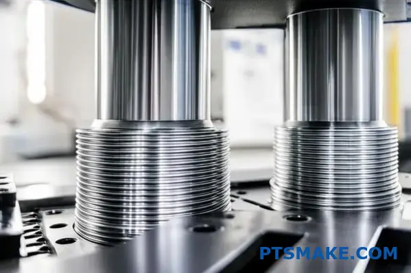
Manufacturing Capabilities
Finally, consider your manufacturing partner. Achieving the tight tolerances for interference fits is not trivial. An H7 hole and a p6 or u6 shaft demand high-precision machinery. At PTSMAKE, we consistently produce parts that meet these exact specifications.
| Feature | H7/p6 | H7/u6 |
|---|---|---|
| Torque Capacity | Medium | High to Very High |
| Disassembly | Possible, with force | Difficult to Impossible |
| Typical Stress | Moderate | High |
| Manufacturing | Demanding | Very Demanding |
Selecting the right ISO fit involves a balanced approach. You must consider torque requirements, disassembly needs, material properties, and your supplier’s manufacturing precision. This framework provides a structured way to evaluate these critical trade-offs for a successful design.
When is a press fit a better choice than a keyway or spline?
Choosing how to join a shaft and hub is critical. It impacts performance and cost. Each method—press fit, keyway, and spline—has its place.
Your decision depends on several key factors. These include torque needs, speed, and budget. Let’s break down the primary differences.
Torque Capacity and Cost
Splines generally offer the highest torque capacity. Keyways are a reliable, cost-effective middle ground. Press fits are excellent but depend heavily on a precise press fit calculation.
A simple comparison looks like this:
| Feature | Press Fit | Keyway | Spline |
|---|---|---|---|
| Torque Capacity | Good to Excellent | Moderate | Excellent |
| Relative Cost | Low to Moderate | Low | High |
| Assembly | Requires Force | Simple | Simple |
This table provides a quick overview for initial design thoughts.
Let’s dive deeper into the technical trade-offs. The best choice isn’t always about raw power or the lowest price. It’s about the right fit for the application.
Balancing and High-Speed Applications
For high-speed rotating parts, balance is everything. Press fits are inherently concentric and balanced. They create a smooth, uniform connection.
Keyways, by removing material, create an imbalance. This can cause significant vibration at high speeds. Splines offer better balance than keyways but are not as perfect as a press fit.
Stress Concentration and Backlash
A major downside of keyways is stress concentration. The sharp corners of the key slot can become failure points under load. Press fits distribute the load evenly around the circumference. This minimizes stress points. However, they introduce hoop stress17 in the hub, which requires careful design.
Backlash, or "play," is another factor. Keyways and splines can wear over time, introducing backlash. This is unacceptable in precision motion control. A properly executed press fit has zero backlash.
At PTSMAKE, we guide clients through these choices daily. We find that for high-precision, high-speed robotics, press fits are often superior.
| Criterion | Press Fit | Keyway | Spline |
|---|---|---|---|
| High-Speed Balance | Excellent | Poor | Good |
| Stress Concentration | Low (Distributed) | High (at corners) | Moderate |
| Backlash | Zero | Prone to develop | Minimal (at first) |
Each joint type presents unique engineering challenges. Press fits offer superior balance and no backlash, ideal for precision tasks. Keyways are simple and cheap, while splines provide the highest torque transmission. The final choice depends entirely on your application’s specific demands.
How to design a press fit that must be repeatedly disassembled and reassembled?
Designing a press fit for repeated use is a unique challenge. Standard press fits often degrade with each cycle. This leads to a loss of holding force.
The main enemies are surface wear and material fatigue. You must account for them from the start.
Key Design Adjustments
To ensure longevity, we focus on a few key areas. Lighter interference is crucial. We also specify harder materials. These changes prevent rapid degradation. Proper press fit calculation is essential here.
| Feature | Standard Press Fit | Reusable Press Fit |
|---|---|---|
| Interference | Higher | Lighter |
| Materials | Standard Hardness | Hardened Surfaces |
| Lubrication | Optional | Often Recommended |
| Assembly | Force | Force / Hydraulic |
This approach helps maintain the integrity of the joint over many cycles.
Mitigating Wear and Fatigue
When parts are pressed together and pulled apart many times, the surfaces suffer. This constant stress causes microscopic damage that builds up over time. This is a common issue we address in our projects at PTSMAKE.
Understanding Surface Wear
Each assembly and disassembly cycle scrapes material from the mating surfaces. This wear reduces the effective diameter of the parts. As a result, the interference, and the holding force, decreases with every use. This can lead to a phenomenon known as fretting corrosion18 if micro-movements occur.
The Role of Material Fatigue
The repeated stress of assembly can also cause the material itself to fatigue. The outer part (hub) is stretched, and the inner part (shaft) is compressed. Cycling this stress can lead to cracks, especially in high-stress areas.
Practical Solutions for Reusability
To combat these issues, we implement specific design strategies.
Lighter Interference Fits
A lighter interference reduces the stress on the materials. It also minimizes the scraping action during assembly. This simple change significantly extends the life of the connection.
Hardened Materials and Surface Treatments
Using materials with high hardness is critical. Harder surfaces resist wear much better.
| Material/Treatment | Benefit |
|---|---|
| Hardened Steel | Resists abrasion and deformation. |
| Nitriding | Creates a very hard surface case. |
| Induction Hardening | Localizes hardness to specific areas. |
Advanced Assembly Methods
For high-precision applications, we sometimes use hydraulic-assisted tools. These tools expand the hub slightly, allowing the shaft to be inserted with minimal force. This almost eliminates assembly-related wear.
Designing a reusable press fit requires careful consideration of wear, fatigue, and assembly methods. Lighter interference, hardened materials, and thoughtful assembly techniques are key to creating a durable, long-lasting connection.
When would you decide a press fit is the wrong engineering solution?
A press fit is a powerful tool, but it’s not a universal solution. Knowing its boundaries is key to robust engineering. You must recognize when another method is better.
This requires moving beyond a simple press fit calculation. We must consider the entire system.
Scenarios Demanding Caution
Consider these red flags. They often signal that a press fit is the wrong choice for your application. Ignoring them can lead to failure.
| High-Risk Scenario | Primary Concern |
|---|---|
| Extreme Thermal Cycling | Loss of Interference Fit |
| Very High Shock Loads | Sudden Component Slippage |
| Brittle Materials | Fracture During Assembly |
| Precise Angular Alignment | Rotational Instability |
Recognizing these boundaries prevents costly design flaws.
Defining the Technological Boundaries
In my experience at PTSMAKE, we’ve seen where press fits excel and where they fail. The boundary is often defined by the operating environment and material properties. Let’s break down the specific limitations.
Extreme Thermal Cycling
When components experience wide temperature swings, materials expand and contract. If the shaft and hub have different thermal expansion coefficients, your carefully calculated interference can vanish. A steel shaft in an aluminum hub is a classic example. At high temperatures, the aluminum expands more, loosening the joint.
Need for Precise Angular Alignment
A standard press fit relies on friction alone. It cannot guarantee precise rotational orientation between two parts. If your components must maintain a specific angle relative to each other, a press fit is a poor choice without a secondary feature like a keyway, spline, or pin.
Very High Shock or Vibratory Loads
Static friction holds a press fit together. However, a sudden, high shock load can momentarily overcome this friction. This can cause the components to slip or even disassemble completely. The assembly’s reliability under impact becomes unpredictable.
Materials Prone to Fracture
Some materials, like ceramics, hardened tool steels, or cast iron, are very strong but brittle. The high tensile hoop stresses created during a press-fit assembly can easily cause them to crack. This leads to a catastrophic brittle fracture19 either during assembly or later in service.
Press fits are unsuitable for extreme thermal cycles, high shock loads, or when precise angular alignment is critical. Using them with brittle materials also risks catastrophic failure, making alternative joining methods necessary in these demanding scenarios.
Master Press Fit Calculation with PTSMAKE’s Expertise
Ready to achieve flawless press fit calculations and superior precision components? Contact PTSMAKE now for a fast, detailed quote—ensure your next CNC machining or injection molding project meets the highest standards. Partner with us for reliability, quality, and unrivaled engineering support from prototype to production!

Discover how this pressure is calculated to ensure your assembly is strong, durable, and reliable for its intended application. ↩
Understand how materials behave under stress to improve your design choices and assembly performance. ↩
Explore how a material’s ability to deform and return to shape impacts assembly strength and failure points. ↩
Learn how this critical stress impacts your design and material choices for a durable assembly. ↩
Understand how individual part tolerances accumulate in a final assembly. ↩
Learn more about how materials permanently change shape under load. ↩
Understand how this adhesive wear occurs and ways to mitigate it during assembly. ↩
Understand this key concept to master the ISO fit system and improve your designs. ↩
Learn how this phenomenon creates internal stress that can compromise your assembly’s integrity. ↩
Learn how this circumferential stress impacts the structural integrity and design of pressure vessels and pipes. ↩
Explore this concept to better understand interface pressures in press fits. ↩
Learn how material properties influence the strength and reliability of your tapered press fit designs. ↩
Learn how static friction impacts the initial force required in your press fit calculation. ↩
Learn more about how different materials expand with heat, a critical factor for your design’s success. ↩
Learn how this criterion predicts material failure under complex loading for safer designs. ↩
Understand how internal forces affect your assembly to prevent material failure and ensure long-term reliability. ↩
Understand how this circumferential stress impacts your design’s integrity and material selection. ↩
Learn more about how this type of wear can compromise your assembly’s integrity. ↩
Understand this failure mode to prevent unexpected cracks and ensure the integrity of your assemblies. ↩